Gallery opened May 2005
Updated: 7 July 2021
Yet more on the Bonnefond compressors


Compressed-Air Road Vehicles |
The principle of compressed-air propulsion seems very simple. Pressurise your storage tank, connect it to something very like a reciprocating steam engine, and off you go. At least you are spared the difficulties, both technical and medical, of using ammonia, petrol, or carbon disulphide as the working fluid.
Unfortunately there are still serious problems. If you have ever pumped up a bicycle tyre, you will know that the pump body gets uncomfortably hot quite quickly. Compressing a gas generates a lot of heat, and all this energy is lost when you store the air and it cools down. The losses can be reduced by compressing the air in two or more stages, and cooling it between the stages, but they are still substantial.
At the other end of the process, using compressed air to run an engine, the main problem is keeping the system working at all. When a gas expands it gets colder, and unless the stored air is perfectly dry ice will start forming in the pipework and engine, and things will soon grind to a halt.
There is a good Wikipedia article on air cars, which gives an impressive list of their disadvantages. A non-obvious one is that it takes a lot of extra energy, apart from the compression, to dry the air sufficiently, and that energy likewise cannot be reclaimed. Compressed air cars are not a practical technology.
Compressed-air systems flourished, insofar as they did, in situations where the smoke, sparks and steam of the much more effective steam engine were not acceptable- in city streets, and down coal mines- and at a time before electricity was a viable means of propulsion. There were several compressed-air tram systems, though none proved very successful, and most were quickly abandoned. Compressed-air locomotives in mines lasted longer, but they too were eventually replaced by electric haulage. Now read on...
 | Left: The Parsey compressed-air locomotive of 1847
|
All the vehicles mentioned above were locomotives running on railway tracks. These have their own page in the Museum. This page focuses on compressed-air road vehicles.
In 1848 Barin von Rathlen constructed a vehicle which was reported to have been driven from Putney to Wandsworth (London) at 10 to 12 mph.
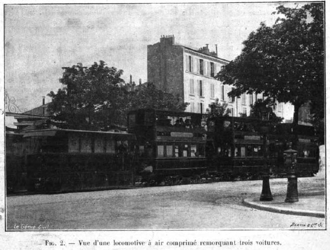
At the end of 1855, a constructor called Julienne ran some sort of vehicle at Saint-Denis in France, driven by air at 25 atmospheres. (350 psi)
THE MÉKARSKI SYSTEM
Most of the images and much of the information on the Mékarski system are displayed by courtesy of John Prentice, whose stunning exposition of the history of compressed-air trams can be seen at Tramway Information. Do not miss it.
Louis Mekarsky (the exact spelling is uncertain) was born in 1843 in Clermont-Ferrand , in the south of France, of Polish origin.
In Louis Mekarski built a standard gauge self-contained tramcar which was tested in February 1876 on the Courbevoie-Etoile Line of the Paris Tramways Nord (TN), where it much impressed the current president and minister of transport Marechal de MacMahon. The tramcar was also shown at the exhibition of 1878 as it seemed to be an ideal transport method, quiet, smooth, without smoke, fire or the possibility of boiler explosion.
Following this success, Tramways Nord used compressed air locos to pull horse trams on their Route E, Saint Denis to Place Clichy, beginning in February 1879. Air at 25 atmospheres (350 psi) was stored in eight reservoirs 0.3 m or 0.4 m in diameter, mounted transversely under the vehicle. These were in two sets, a main and a reserve set. The two-cylinder engine drove the front axle through the usual cranks set at 90 degrees to avoid stalling at dead centre; cylinder dimensions were a modest 125 mm bore and 260 mm stroke.
The compressed-air locos were soon withdrawn due to a number of accidents, possibly caused by icing in the pipes of the brakes, which were also worked by compressed air. This strikes me as an inherently flawed concept; if you ran out of air the brakes didn't work. A car where the brakes stopped working completely if you ran out of petrol would probably not be a saleable proposition. The servo brakes fitted to almost all cars these days retain enough engine vacuum for at least one serious stop if the engine ceases to run, and when that is exhausted the brakes still work, even if some serious foot effort is required.
 | Left: A of a tram built by Mekarski and used in early trials in Paris. (Drawing 1875)
|
 | Left: A bouillotte mounted on the front of a tram built by Mekarski and used in early trials in Paris. (Drawing 1875)
|
According to La Nature, the storage capacity was 2640 litres, holding kg of air at 80 kg/cm2. This weighed 262 kg at 15 degC. The range was about 16 kilometres, by which point the storage pressure had dropped to 12 kg/cm2.
 | Left: The regulator (air control valve) on top of the Mekarski bouillotte.
|
Mékarski went on to run an extensive compressed air tram system in Nantes, opening in 1879. The first trams had ten steel storage cylinders between the frames and were charged to 30 atmospheres, reduced to 4 to 6 atmospheres at the engine, which was very similar to the Paris engine. An additional 32 trams were bought between 1898 and 1900; these were more powerful than the first series, with air storage at 60 atmospheres (840 psi) and with both axles driven to improve adhesion. The compressed-air trams were replaced with electric trams in 1911.
 | Left: A Nantes tram recharging with air and blowing steam through the bouillotte.
|
Mékarski system tram networks were also built in other towns in France: Vichy (1895), Aix-les-Bains (1896), La Rochelle (1899), and Saint-Quentin (1901).
There is a Wikipedia article on the Mekarski system.
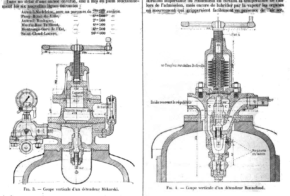 | Left: The regulators for the Mekarski and the Bonnefond system on top of the bouillotte.
|
THE BONNEFOND SYSTEM AND THE CGO
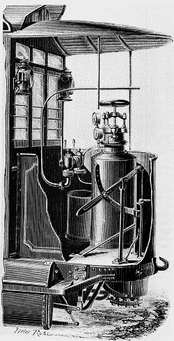
The water in the Mekarski bouillotte cooled quickly as air was blown through it, and it was initially reheated by blowing steam through the water when the tram stopped to recharge the air tanks. Later a certain Monsieur Bonnefond introduced an internal coke firebox to provide continuous reheating of the water. This approach appears to have only been used in the Paris operations of the Compagnie Générale Des Omnibus (CGO).
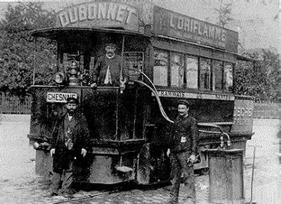
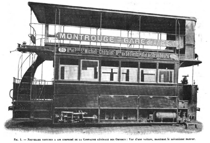 | Left: A compressed-air tram of the Compagnie Générale Des Omnibus of Paris, system Bonnefond
|
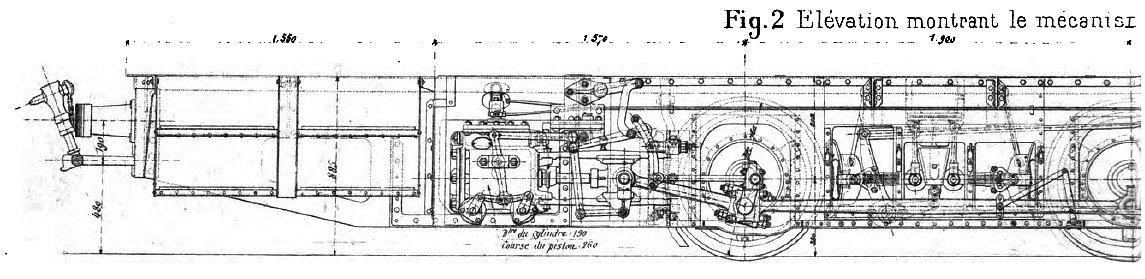 | |
Above: Side view of CGO tram: 1901
|
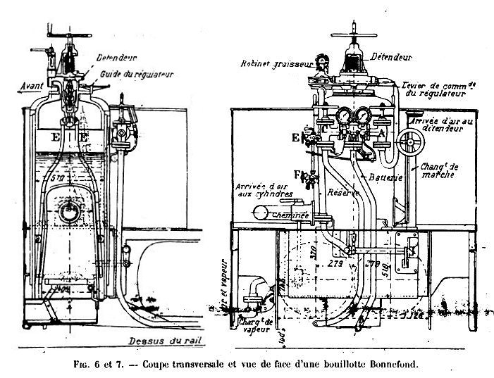 | Left: The Bonnefond bouillotte
|
 | Left: The Bonnefond bouillotte
|
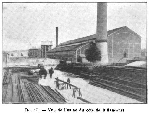
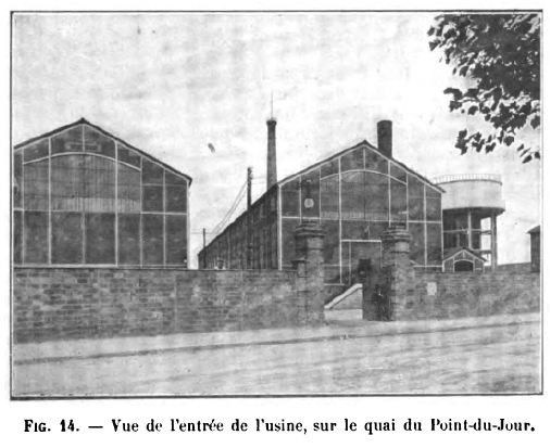
Compressed-air trams need a network of refilling points to recharge their storage cylinders, supplied by a central compressor station. For this purpose COG built a large usine (power-plant) at Billancourt on the bans of the Seine, to the West of Paris.
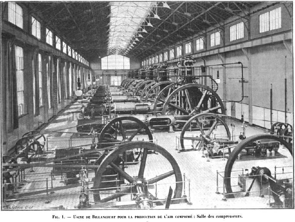 | Left: The compressor hall at the Billancourt usine in Paris.
|
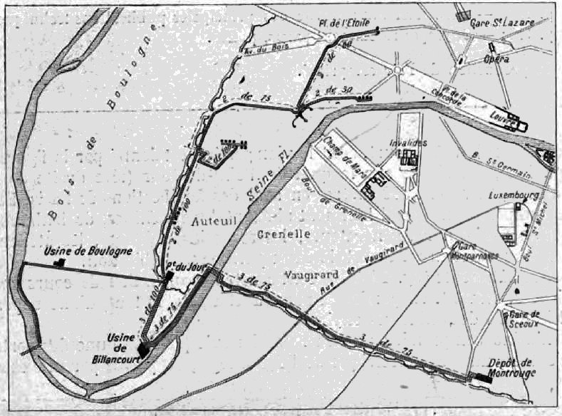 | Left: The compressed-air distribution network of the CGO in Paris: 1901
|
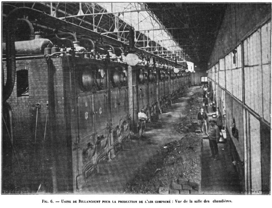 | Left: The boiler hall of the Billancourt usine of the CGO: 1901
|
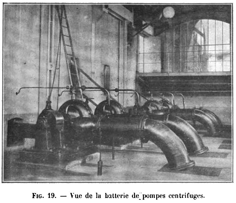 | Left: Centrifugal pumps for raising water from the Seine at the Billancourt usine: 1901
|
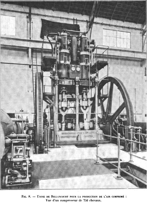 | Left: 750 HP compressor in the Billancourt usine: 1901
|
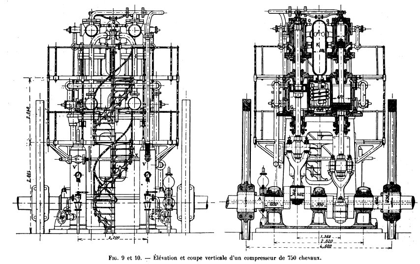 | Left: 750 HP compressor in the Billancourt usine: 1901
|
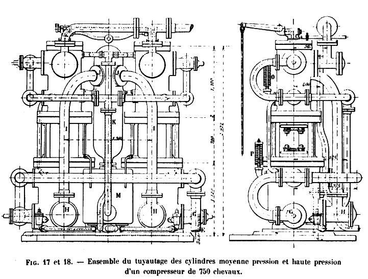 | Left: 750 HP compressor in the Billancourt usine: 1901
|
 | Left: 750 HP compressor in the Billancourt usine: 1901
|
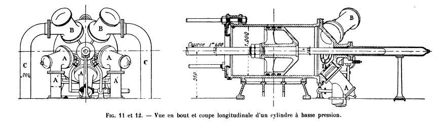
 | Left: Air inlet valve for the low-pressure stage of the Billancourt compressors: 1901
|
 | Left: Valves of the Billancourt compressors: 1901
|
 | Left: Water injection pump for the Billancourt compressors: 1901
|
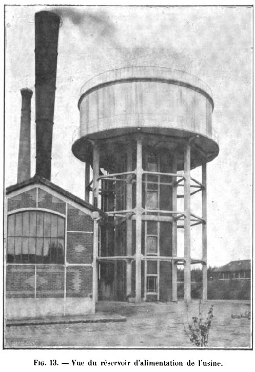 | Left: The Billancourt usine of the CGO with its two chimneys and water-tower: 1901
|
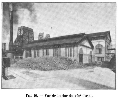 | Left: The Billancourt usine of the CGO: 1901
|
 | Left: The Billancourt usine of the CGO with its two chimneys:
|
 | Left: The Billancourt usine of the CGO with its two chimneys: 1901
|
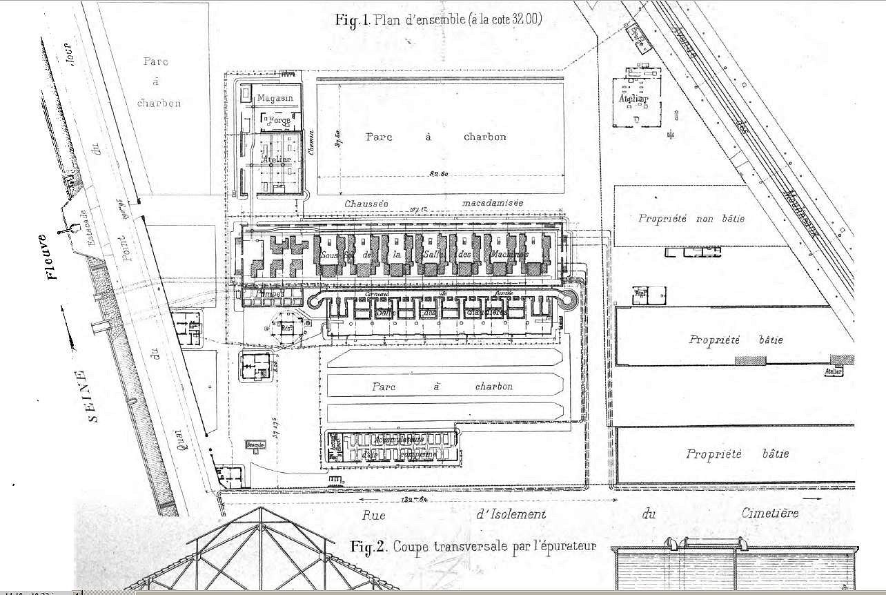 | |
Above: Plan of the Billancourt usine of the CGO: 1901
|
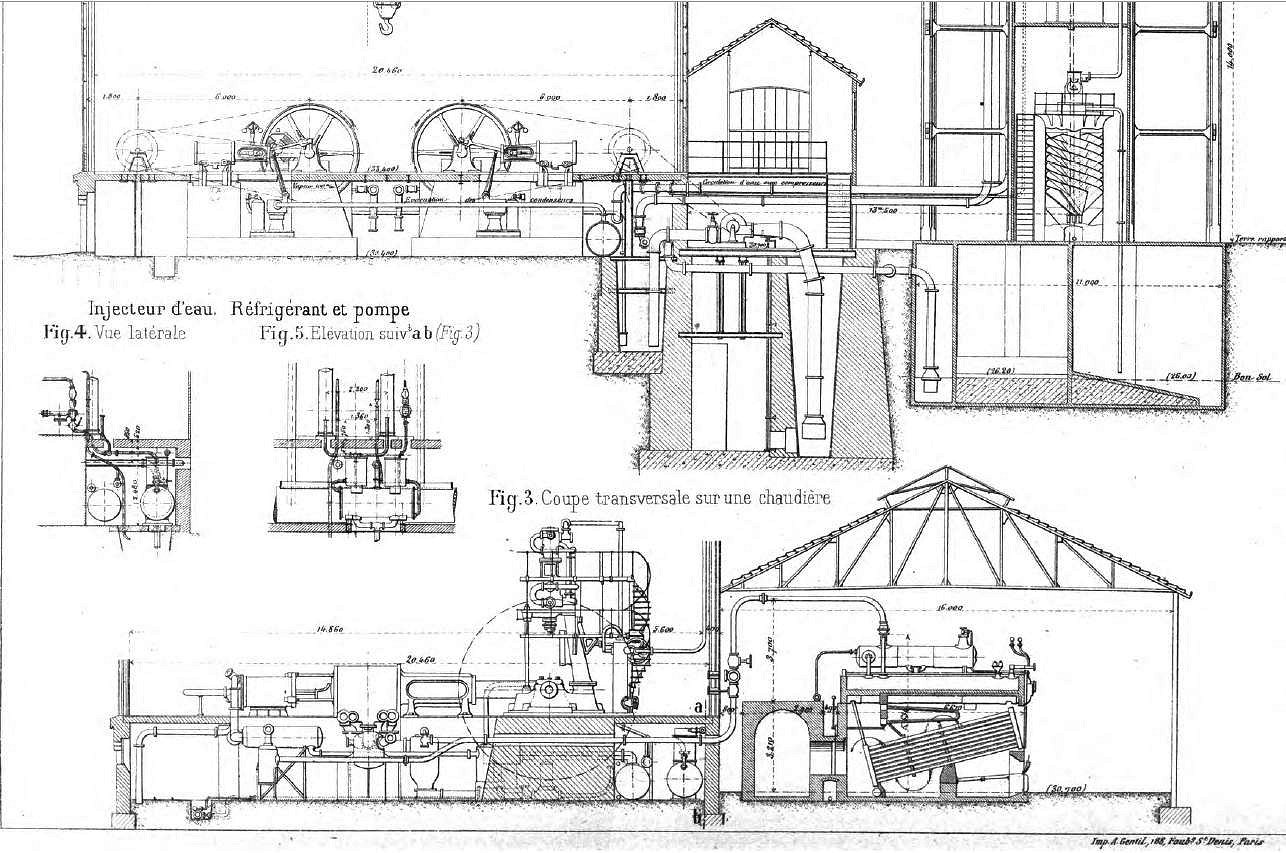 | |
Above: Side view of the Billancourt usine of the CGO: 1901
|
"The Second Avenue Railroad of New York city, has one of the Pneumatic Tramway Engine Company's cars. Upon each platform is a steel lever, by means of which the car can be started, stopped or its direction reversed. The car is of the same general model as that of ordinary street cars. It has six tubular air receivers situated under the floor of the car. The air is compressed by an engine which is standing at the side of the depot, and is introduced by a rubber hose into these receivers. That air passes through an engine situated between the axles, and propels the car.""The car lately ran from 63d to 95th street and back in about 20 minutes, with two or three stoppages. It is claimed for the car thus inspected that it can be stopped more readily than the horse cars, and that its rate of speed can be increased to 30 miles per hour, while it can make 9 miles per hour and still not appear to go faster than the horse cars. The car which was run is only a model, and it takes about four hours to charge its receivers with air, but machinery has been ordered which will perform the work in less than a minute." "One of these air engines, it is said, can easily draw a whole train of ordinary street cars. A company composed of 25 capitalists has been formed to manufacture cars upon the above model. It has already received an order for five from the Second Avenue Company. These will be used on the upper part of the Second Avenue route." Source: Manufacturer and Builder Volume 10, Issue 5, May 1878 |
![]()
Compressed Air Locomotives in New York City:
"The Third avenue horse railroad has now in operation one small locomotive, which is used instead of a span of horses to propel one of their ordinary cars. The machinery is partially on the front platform and partially below the bottom of the car and under the side seats, which will accommodate about half the number of passengers that the car will hold. The propelling power is compressed air, which is stored up at the depot up-town by a stationary engine, and tapped by the car from its reservoir at every trip, the capacity of the reservoir in the car being sufficient to contain compressed air enough for a down and up trip.""It appears to give satisfaction so far, and if this continues, it will afford great relief to the horses, which, when used on street cars, suffer much from the continual stopping and starting connected with this mode of travel. The Society for the Prevention of Cruelty to Animals will, we hope, encourage this new enterprise." Source: From Manufacturer and Builder Volume 11, Issue 11, November 1879 |
![]()
Revival of the Use of Compressed Air as a Motive Power
By Dr P H Van Der Weyde
"Lately an important problem has again been brought to public notice -- namely, the propulsion of street cars by means of compressed air, carried on the car itself.""The solution of the problem requires the execution of two kinds of contrivances -- first, a reservoir strong enough to withstand considerable pressure, and, secondly, a motor machine to be put in operation by this pressure. The reservoir is by preference made in the form of cylinders, of say one or two feet in diameter, so that they can be placed under the seats of the car, and of a length sufficient to utilize all the space afforded. The motor is best placed under the floor of the car, now a common method in the electric trolley cars, while the regulating devices are on both platforms where the motorman performs his duty." "It is evident that this system offers peculiar advantages, especially by reason of its apparent simplicity. The cylinders containing the compressed air -- the motive power -- are charged at the station and need no further attention, as is the case with locomotive boilers, where the chances of safety depend on the engineer and stoker. All the heavy machinery used for the production of the primary power is stationary, and no power is wasted to move it about as in the case of the locomotive, the only weight to be transported is the motor and the cylinders containing the compressed air. Summing up the advantages, they are:" 1. No dead weight of coal or fuel on board. 2. No dead weight of water, boiler, furnace, and other material which has to he stabled, the real primary motor, which is a stationary structure of large dimensions, and therefore economical, as the economy increases at a very large ratio as the engines are increased in size. 3. The compression of air is going on continually in the reservoirs, and is always connected with the gauges, so as to insure safety. "The first application of this principle was seen some six or eight years ago at the Harlem station of the Second Avenue Railroad. It was intended for the propulsion of trains, and the compressed air reservoirs consisted of two huge cylinders placed horizontally, with a space between, through which the engineer could see the forward track while standing on the motor, and having the train of cars behind." "A few years later I saw some interesting experiments of thie same character at the Delamater works, where pipes were laid to quite a distance from the works, and at which pipes the cylinders could take up new supplies of compressed air without going back to the supply station." "A syndicate has been formed to introduce this system of street transportation, so that we will have another additional method in practice." Source: From Manufacturer and Builder Volume 26, Issue 12, December 1894 |
THE HARTLEY AIR-POWERED TRICYCLE
 | Left: A Compressed-Air Tricycle for mail delivery
|
THE PNEUMATIC CARRIAGE COMPANY: 1898
![]()
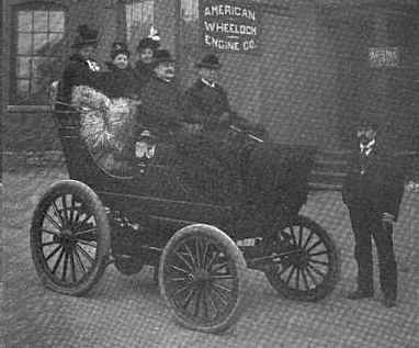 | Left: The Pneumatic Carriage Company's compressed air car: 1898
|
From The Horseless Age for October 1898:
"In 1895, the Pneumatic Carriage Company was organized under the laws of West Virginia, with an authorized capital of $5,000,000, and with offices at 253 Broadway, New York. The organizers had been conducting experiments with compressed air motors for street railway service for several years, and naturally turned toward the motor vehicle when it received its first impetus in America. The president and manager of the company is A. H. Hoadley, who has been in charge of the experiments at the works of the American Wheelock Engine Company, Worcester, Mass.The first carriage built by the company, illustrated herewith, was completed in November, 1896. It has seating accommodations for six passengers, weighs 2700 pounds, and will run 20 miles over ordinary good roads on one charge. A grade of 20 per cent is claimed to be surmountable. The wooden wheels are 30 and 42 inches respectively, and pneumatics of 4 inches diameter render riding as easy as possible. The motor, of the reciprocating type, weighs 400 pounds and operates at 350 revolutions, when the carriage is making 15 miles an hour. Ordinary compensating gear and hub steering are employed. In order to heat and expand the air before it enters the motor, it is surcharged with hot water, carried in the vehicle in a separate tank and kept at a temperature of 400 degrees Fahrenheit. Five pounds of water are required for each mile traversed. All the above machinery is spring-supported, to relieve it from the shocks of the road. This carriage has been tested for the past year or more in the streets of Worcester and Washington, DC" |
This account positively bristles with impracticalities. Note the very limited range, and the need to carry around a tank of hot water to heat the air; if five pounds of hot water were expended per mile, and the range was 20 miles, the contents of the full tank would have weighed 100 pounds. The engine appears to have been extraordinarily heavy at 400 pounds.
Note that the hot water was stored at 400 degF. The normal boiling point of water is 212 degF, so clearly it was stored under pressure. In fact, under considerable pressure, because water boils at 400 degF at about 230 psi- a greater pressure than that used in most steam boilers of the day. The water tank would have to withstand this pressure, so it would have to be a lot stronger and heavier than a simple tank. This clumsy and potentially dangerous setup seems to indicate that the Pneumatic Carriage Company had considerable difficulty in storing enough energy to heat the air, even for the very limited range that was claimed.
Therefore "filling up" would be quite a business. You would need a filling station that not only had a supply of compressed air (which I suspect was at considerable pressure- the later Mekarski system stored air at 60 atmospheres = 840 psi) but also a constantly-hot steam boiler working at an unusually high pressure. And with a 20-mile range you would need an awful lot of filling stations. You can see why this idea did not take off.
The following news item provides a little more information:
"A Compressed Air Carriage. Nov 1896"
"For some time past experiments in compressed air motors have been conducted at the factory of the American Wbeelock Engine Company, Worcester. Mass. These experiments have been very exhaustive, covering the application of compressed air motors to both track and road vehicles. To gather data for tbe latter class of vehicles, the Pneumatic Carriage Company, which is the name of the company working in this particular line, have just completed a two-seated carriage, which was publically exhibited in a procession held on Flag Day, Oct. 31, through the streets of Worcester, although close inspection was not allowed, inasmuch as tbe present vehicle is merely experimental and the company are not yet prepared to furnish specific information. President Hoadley states, however, that the experiments will be continued until a thoroughly satisfactory model is obtained, when steps will be taken to introduce compressed air vehicles for public service in cities.""The Pneumatic Carriage Company has New York offices at 3S3 Broadway, connected with those of the American Wbeelock Engine Company." |
THE AIR VEHICLE COMPANY CAR: 1900
![]()
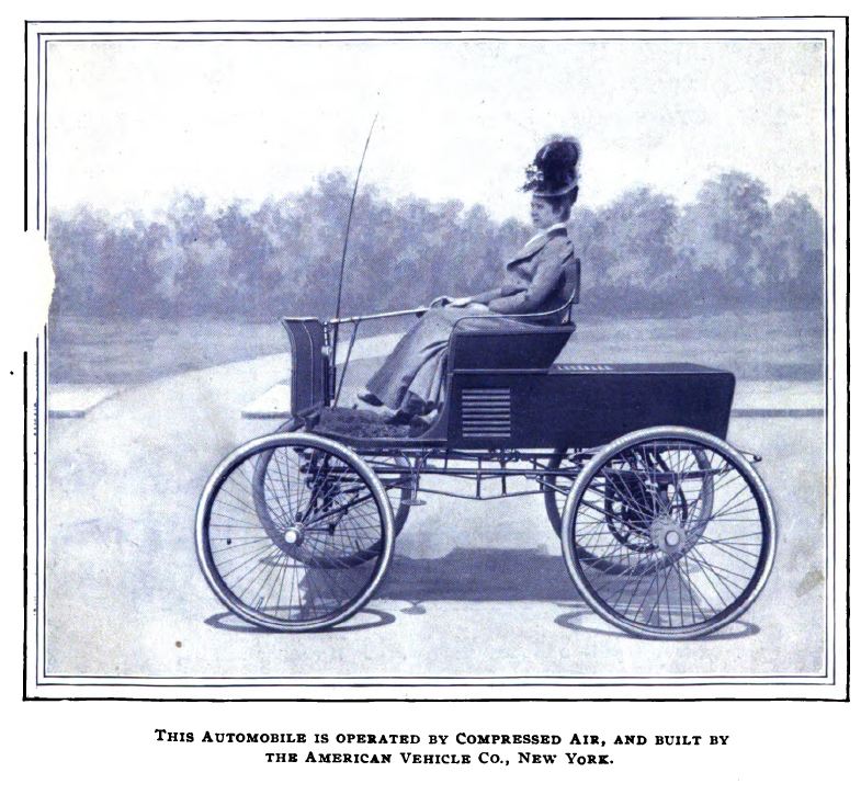 | Left: The Air Vehicle Company car: 1900
| ||
"On a recent trial on a bad road this wagon was operated with a consumption of 60 cubic feet of free air per mile. The condition of the road was much below the average, and the trail was not one which would give the most economical results in the use of the power, yet under these conditions it would be seen that the storage has capacity to run the wagon 20 or 30 miles. And as it is estimated that air can be compressed for less than 4 cents per 1,000 cubic feet, it is believed that it will prove a desirable and economical power for propelling omnibusses and delivery wagons which have a definitely determined route to travel." |
THE AIRMOBILE COMPRESSED-AIR CAR: 1914
![]()
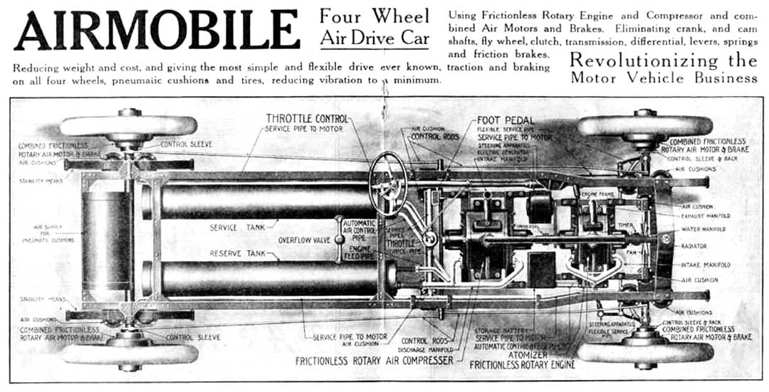 | Left: Drawing of the Airmobile from above: 1914
|
Given the relatively small amount of air storage provided, the whole compressor/air-motor system is just a very cumbersome and inefficent transmission system. It appears that all the heat generated by air compression was simply thrown away. To add to the complications, the suspension was partly by pressurised air-cushions, with their own air reservoir; see extreme left of drawing. In the drawing above the air-motors on each wheel are shown as no larger than an ordinary hub, and I doubt if this was realistic. Having four motors rather than one central motor much increases the complexity, and presumably also the unsprung weight. No means of preventing the air-motors from icing up is visible.
The 25 December 1916 issue of “The Automobile Journal” published a section titled “Novel Power Plants” (page 21) in which the following appeared on page 26:
“Features of the New Airmobile.“THE Rotary Products Company, Los Angeles, Cal., has adapted the rotary principle of generating power from gasoline and storing It as compressed air by driving an air compressor, designed on lines similar to the engine, and In turn piping the air to rotary air motors attached to each of the four wheels. This Is probably the most unique Idea In motor car propulsion that has been presented this year. “Its practicability rested with the perfection of the rotary principle which Involved largely the question of maintaining the necessary pressures In the explosive chambers which heretofore has been impossible because of leakage. The maker of this motor, however, claims that leakage has been negatived and that the engine can be run at low speed and produce high pressures, whereas formerly rotary engines were run at high speed and only produced low pressures. “A further and Interesting fact about the mechanism Is that It Is applicable not only as a rotary gasoline engine, but as an efficient air compressor, an air motor or can be adapted as a clutch or brake. The rotary engine is used to drive a rotary air compressor, both machines being hung on cross members in the forward part of the chassis. The air Is stored In tanks and piped to the four wheels, which are operated by individual air motors, or as brakes. “By this method of generating and transmitting the power the maker claims to have obtained not only a frictionless drive, but to have eliminated crank and camshafts, flywheel, clutch, transmission, levers and friction brakes; reduced weight and cost of construction and incidentally have adapted a set of air cushions which supplement the springs and reduce the vibration to a minimum.” |
A somewhat less than perceptive account.
No production vehicles resembling the drawing above were ever produced, and it appears that the idea was abandoned sometime around 1916.
THE LEE BARTON WILLIAMS COMPRESSED-AIR CAR: 1926
![]()
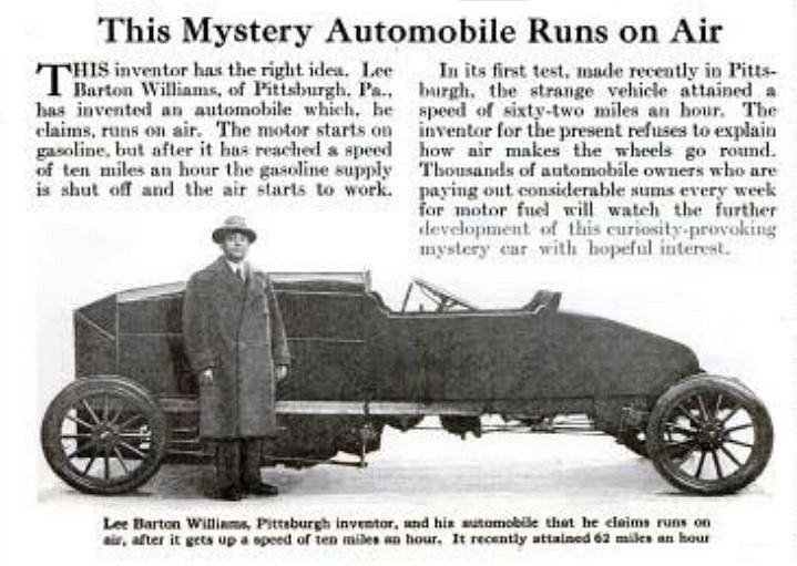 | Left: The Lee Barton Williams compressed air car: 1926
|
THE F E KENNEY COMPRESSED-AIR CAR: 1926
![]()
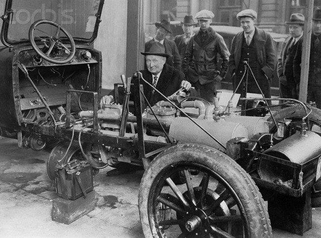 | Left: The F E Kenney compressed air car: 1926
|
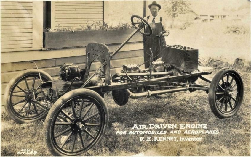 | Left: The F E Kenney compressed air car: 1926
|
THE ROY J MEYERS COMPRESSED-AIR CAR
![]()
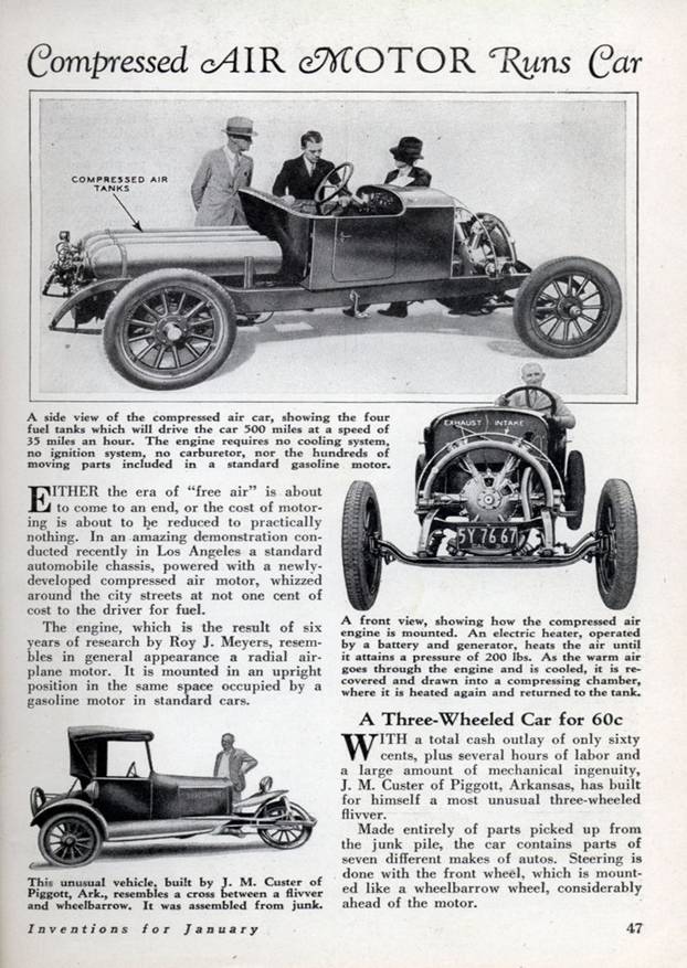 | Left: The Roy J Meyers Air car: 1932
|
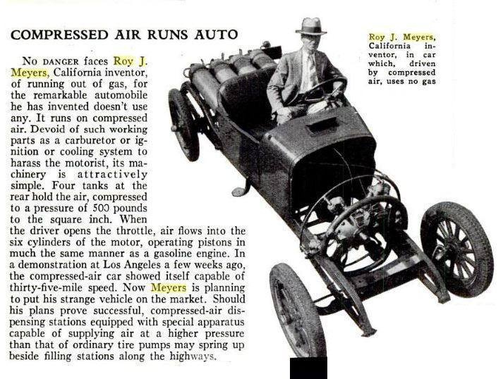 | Left: The Roy J Meyers Air car: 1932
|
 | Left: Roy J Meyers patent: 1926
|
This self-refilling perpetual motion scheme resurfaces from time to time, always with the assumption that just the right combination of injectors and check-valves (there are always lots of check-valves) will make it work. The phrase 'free-range air car' is likely to crop up and should be a warning to the reader. To get a taste of this stuff try aircaraccess.com. 'Suppressed inventions' often crop up; see this site. That is just the page which includes the Meyers car.
One thing is clear. The arrangement in the patent will provide compressed air- for so long as that stored in the air reservoirs lasts. This should be long enough to impress potential investors...
CONTEMPORARY COMPRESSED-AIR CARS
There are several on-going projects for air-driven cars; see Wikipedia. The page includes a daunting list of air-car disadvantages.
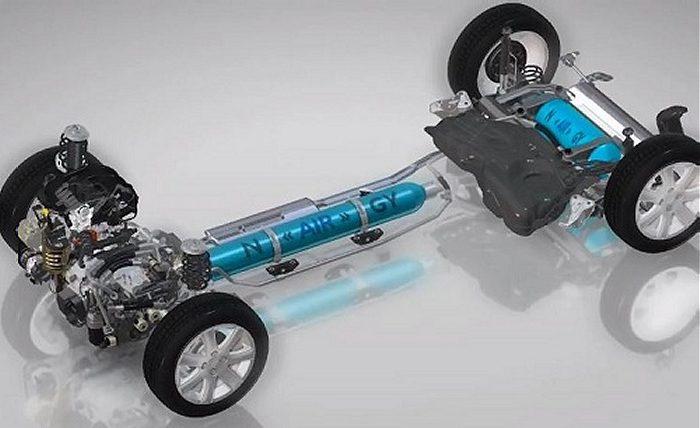
THE MDI AIR CAR
The French MDI Air Car is apparently no longer a live project; the domain name is for sale. Apart from straightforward compressed-air propulsion, they claimed to be also developing dual-energy engines, in which a fuel (petrol, diesel, oil, alcohol or gas) is burned in an external continuous combustion chamber to heat the air and give more range. The amount of toxic gases released was claimed to be very low.
One of the vehicles proposed had the following specs:
![]()
![]()
Weight Empty220 kg
Max speed70 km/h (43 mph)
Range (urban)220 km (136 miles)
Reservoir Pressure 350 bar (5076 psi)
Reservoir Volume175 litres
Refill Time1.5 minutes |
The following publicity material was released. After a lot of guff about internet connectivity, GSM telephone connectivity, a GPS guidance system etc, etc, which had nothing to do with the means of propulsion:
"The Mini C.A.T is a simple, light urban car, with a tubular chassis that is glued not welded and a body of fibreglass..."Most importantly, it is incredibly cost-efficient to run – according to the designers, it costs less than one Euro per 100Km (about a tenth that of a petrol car). Its mileage is about double that of the most advanced electric car (200 to 300 km or 10 hours of driving), a factor which makes a perfect choice in cities where the 80% of motorists drive at less than 60Km. The car has a top speed of 68 mph. "Refilling the car will, once the market develops, take place at adapted petrol stations to administer compressed air. In two or three minutes, and at a cost of approximately 1.5 Euros, the car will be ready to go another 200-300 kilometres. As a viable alternative, the car carries a small compressor which can be connected to the mains (220V or 380V) and refill the tank in 3-4 hours. "Due to the absence of combustion and, consequently, of residues, changing the oil (1 litre of vegetable oil) is necessary only every 50,000 Km. "The temperature of the clean air expelled by the exhaust pipe is between 0 - 15 degrees below zero, which makes it suitable for use by the internal air conditioning system with no need for gases or loss of power." |
Elsewhere the claimed top speed was very modest, at 43 mph, and the range less than stunning at 136 miles. The company made the usual claims about the car being pollution-free, which is of course true in actual operation. But since compressed air is being used merely for energy storage, power will have to generated somewhere else. And proponents of air cars never mention that compressing air is inherently inefficient, with all the heat of compression lost.
The air storage tank was to be made of carbon-fibre wound on a thermoplastic liner. Kerry Stiff tells me:
"The storage vessel they were using is known as a Composite Overwrapped Pressure Vessel or COPV. COPVs are expensive, fragile and dangerous. They have a limited number of fill-discharge cycles. There is a pressure at which the overwrap fibre goes from compression to tension. Every time you cross this pressure value, rising and falling, you use up one cycle. COPVs must be filled very slowly to prevent overheating.""NASA uses COPVs with great caution. The procedure for charging COPVs at KSC is so onerous that we charged them at CERN. These COPVs were not certified for transport under pressure on public roads. We had the road closed from CERN to the Geneva airport so we could transport AMS to the airport. AMS was airlifted to KSC by a US Air Force C5-M. The C5-M landed on the shuttle runway at KSC alleviating DoT issues in the USA. This was the coolest airplane ride I have ever had!" |
As of 2018 no MDI design had reached production. There is a Wikipedia page on MDI.
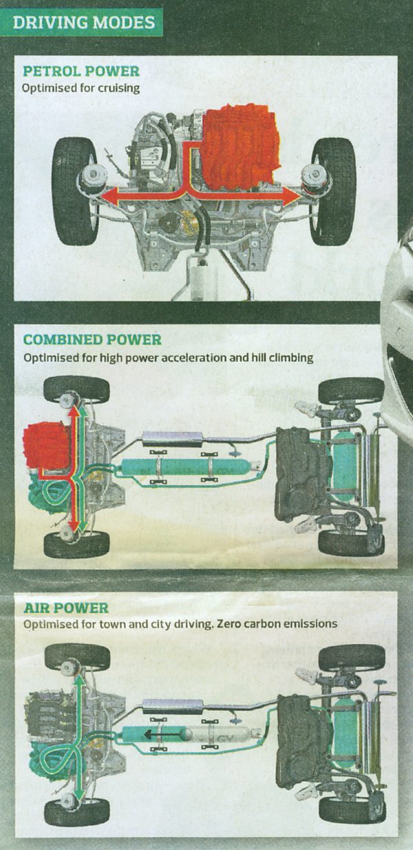 | Left: Peugeot: 2013
|
 | Left: Computer rendering of the Peugeot car: 2013
|
THE ZPM AIR CAR SCHEME
Searching for 'air cars' with Google rapidly brings up the Zero Pollution Motor Company, who are promoting the Airpod 2.0 compressed air-powered car. (sic) Judging by the pictures available, the car itself has indeed been compressed. Their website shows lots of renderings but as far as I can see no real hardware. They are looking for investment...
![]()
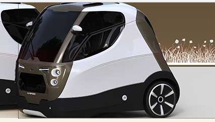 | Left: ZPM Airpod 2.0: 2018
|
Some technical details have been released. The compressed air engine is reversible, (?) and has two in-line cylinders with variable valve timing. The capacity is only 430cc (26.2inł). The crankcase and cylinder head are aluminum. Each cylinder is described as having having 'an included active chamber'; this seems to refer to some sort of auxiliary piston that prevents dead-centre issues, though there shouldn't be any with a two-cylinder engine. The engine is currently somewhat mysterious.
Drive is to the rear wheels through an automatic gearbox with 3 gears + reverse. If there is a reverse gear it's not obvious why you need a reversible engine; perhaps it refers to using the engine as a compressor. There is claimed to be electronic management of kinetic energy recover during deceleration, and presumably this refers to recompressing air.
We now come to the all-important air storage tank. This is spec'd as "Type IV, thermoplastic liner and carbon fibre wiring. Volume: 2 × 125 litres. Pressure: 248b". Presumably this means two tanks at 248 Bar, which is 3600 psi in round numbers. Tank design is said to be based on EC norm ECE R110, which is titled “High pressure cylinders for the onboard storage of natural gas as a fuel for automotive vehicles". Research shows that this standard does cover wound cylinders. See here.
ZPM claim to have a license from MDI (above) which given MDI's uncertain status is perhaps not reassuring. The claim of zero pollution of course ignores how the energy to compress the air was generated.
OTHER COMPRESSED-AIR VEHICLES
The Odd Bicycle gallery of the Museum has a projected compressed-air bicycle as an exhibit. It looks completely impractical.
One of the most prestigious of the early motor cars was the French built Delaunay-Belleville. They built some big cars with 11.8 litre engines for the Russian Tsar in 1909. These were fitted with Saurer compressed-air starting gear, which could also be used to inflate tyres, jack up the wheels, or blow a whistle. However its most important feature was that the air reservoir was sufficient to drive the car for about 400 yards without even starting the engine, allowing the Tsar to make a quick getaway from an assassination attempt.
Given the history of Russia, this was not just a theoretical possibility. Tsar Paul I was murdered in his own bedoom in 1801. Alexander II survived assassination attempts in 1866, 1879 (twice), and in 1880, when the dining room of the Winter Palace was blown up, before he finally ran out of luck in 1881.
There is, of course, another and far less benign class of things very often powered by compressed air: torpedoes.
![]()
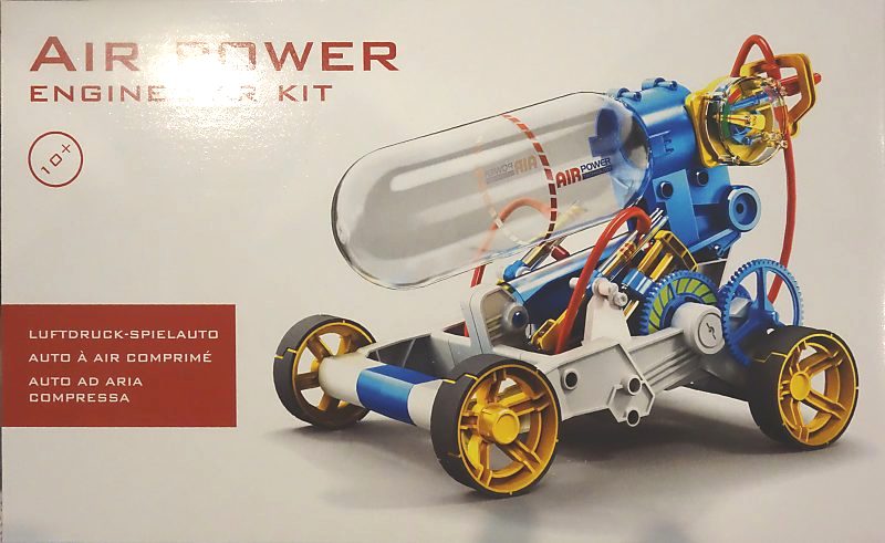 | This intriguing kit was spotted in the gift shop of the Science Museum in Milan. It is a very fine science museum, though for obvious historical reasons they do bang on a bit about Leonardo da Vinci. My view is that anyone can design a helicopter that does not work.Working solely from the picture, the engine seems to be two very simple single-acting cylinders (to avoid dead-centre problems) driving a common crankshaft in the upper forward part of the grey chassis. There are then at least two stages of reduction gearing in the drive to the rear axle. How the crankshaft connects with the first spur gear (with the green segments) is unclear. The info on the back of the box (see below) says there is a pump-up bar, a pressure gauge and a safety valve, none of which are visble. The round thing at the back of the air reservoir appears to be the on/off valve. I have no idea what pressure is used or how far this thing will run. Author's photo. Milano May 2018. |
 | The information on the back of the box. The text under the reflection is 'NO BATTERY'.Author's photo. Milano May 2018. |
![]()
EXTERNAL LINKS
Compressed air vehicles in general: aircaraccess.com
Interesting historical material, but some worrying references to what appears to be perpetual motion.
For French references, Google on "locomotive ŕ air comprimé". For example: tramways_mecaniques
Porter locomotive links:
www.nrhs.com/web_exclusives/fireless_cooker
![]()
![]()

|