Gallery opened: March 2005
Updated: 13 Mar 2023
Frot's Ammonia Motor added
Index added
CONTENTS OF THIS PAGE


CONTENTS OF THIS PAGE
CONTENTS OF THIS PAGE
Ammonia Motors |
THE PRINCIPLE
The ammonia motor is a device so obsolete and forgotten that unearthing any information at all has proved quite difficult. The concept is thus; take a tank of ammonia, by which I mean pure liquid anhydrous ammonia, and not the weak aqueous ammonia solution that used to be sold for cleaning purposes. (I can remember my mother having a bottle of "Scrubb's Cloudy Ammonia", though why it was cloudy and who Scrubb was are entirely mysterious) The liquid ammonia is allowed to evaporate, which it does readily at ambient temperature, and the resulting gaseous ammonia used to drive something very like a steam engine.
There are of course serious problems with such a simple process. The exhaust gases are not only choking, but they are actively poisonous, and explosive to boot, so exhausting direct to atmosphere is not an option; there is also the point that ammonia costs money so you don't want to throw it away. Another difficulty is that the evaporation cools down the anhydrous ammonia, the rate at which gas is evolved slows down, and the engine is liable to freeze up.
Emile Lamm* solved both snags in one go by absorbing the exhaust ammonia in a tank of water that surrounded the anhydrous ammonia storage tank. Heat is evolved when the exhaust ammonia dissolves, keeping the anhydrous ammonia warm and aiding its evaporation. This neat process is reminiscent of a similar scheme using caustic soda: see The Soda Locomotives".
* It appears to have been Lamm, anyway. I have so far only discovered one earlier ammonia motor inventor, a Mr Gordon, and technical details are sadly lacking.
 | Left: The Delaporte Ammonia Engine: 1859
|
Apparently this water "has been deprived by heat of its ammonia" though how this is kept separate from the ammonia solution being pumped in is a good question; possibly it's simply a matter of density. This water, on leaving l by a connection not shown, is cooled and conveyed into the tank t, which is the source of the water sprayed into f.
It's a bit hard to say what the value of this engine was. it appears to have worked on a mixture of ammonia and steam, since the chamber f is referred to as both a condenser and a dissolver. If so, presumably the heat generated by the ammonia dissolving would have worked against the condensation of the steam, which doesn't sound clever.
Delaporte's engine is described in a Knight's book of 1881; however it must have been built long before that, judging by the beam-engine format, which would have been considered very antique in 1881.
TELLIER & FLANDRIN'S AMMONIA CARRIAGE
![]()
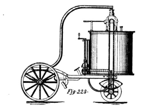 | Left: Tellier and Flandrin's Ammonia Carriage: 1860
|
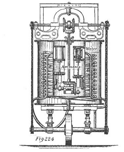 | Left: Tellier and Flandrin's Ammonia Carriage: 1860
|
 | Left: Frot's Ammonia Motor: 1869
|
 | Left: Report from Mechanic's Magazine on the Froment Ammonia Engine: 18??
|
From Knight's American Mechanical Dictionary, 1881 Edition
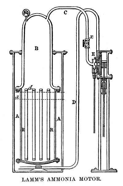 | Left: Lamm's Ammonia Motor: 1869
As a boy he showed decided mechanical ingenuity, and in 1869 devised an ammoniacal fireless engine for the propulsion of street-cars. The system was tested by street railway companies in New Orleans, New York, St. Louis, and other cities, with satisfactory results; but owing to Mr Lamm's premature death and unfortunate management on the part of the company that controlled the patent, the motor has not been put into practical operation in the United States. The system has been introduced in France and Germany, where it has been improved and perfected, so that at present (1887) it is extensively used for street-cars and vehicles." |
The best-known application of Lamm's ammonia power system was the Saint Charles Avenue Streetcar in New Orleans. The line was established as "The New Orleans and Carollton Rail Road Company" in February 1833, and a service began in 1835. Through the early years the cars were successively powered by horses, mules, overhead cables, Lamm's ammonia engines, and steam engines; none were very satisfactory, and it was finally electrified in 1893.
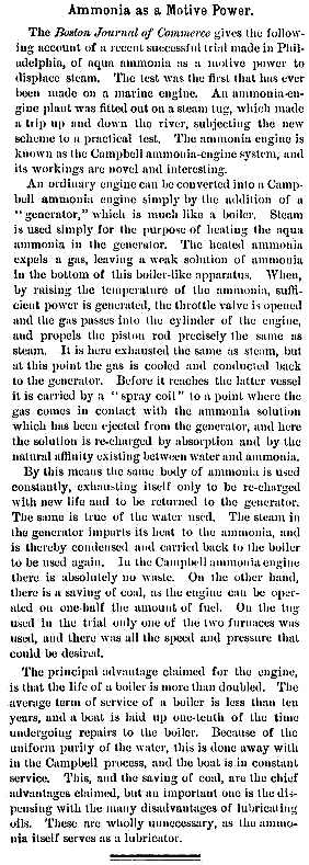
THE HORACK AMMONIA ENGINE: 1891
![]()
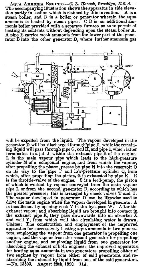 | Left: Report on the Horack Ammonia Engine patent: 1891
|
 | Left: Article on the Campbell Ammonia Engine: 1891.
The claim that it used half the amount of fuel raises the eyebrows; if this was really the case I should have thought we would have heard a lot more of Campbell. |
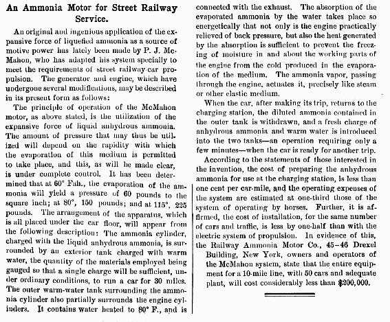 | Left: Article on MacMahon's Ammonia Motor: 1892.
|
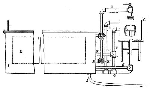 | Left: MacMahon's Ammonia Motor: 1894.
|
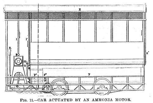 | Left: Streetcar powered by MacMahon's Ammonia Motor: 1894.
|
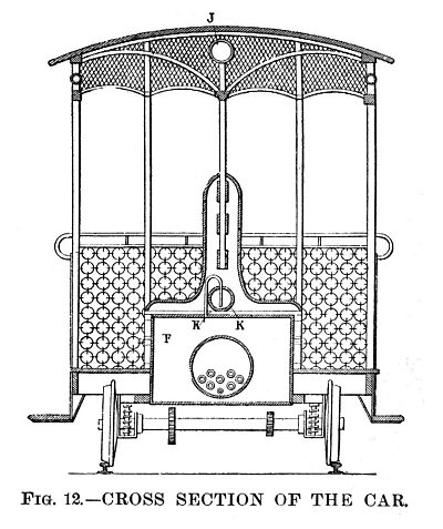 | Left: Streetcar powered by MacMahon's Ammonia Motor: 1894.
|
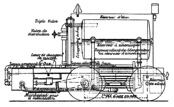 | Left: Side View of the French Ammonia Locomotive: 1894.
|
An interesting feature is that the brakes were also powered by ammonia pressure, which to me seem to have the distinct disadvantage that when you run out of anhydrous ammonia the brakes stop working- something that seems rather less than desirable in a loco intended for steep inclines. Hopefully there was a handbrake as well. In a rare diversion into hard fact, the article tells us that the ammonia brake cylinder was 76mm in diameter.
 | Left: Section of the French Ammonia Locomotive: 1894.
|
 | Left: Plan View of the French Ammonia Locomotive: 1894.
|
Images and information on the French Ammonia Locomotive most kindly provided by Haruyuki Makishima
One thing that all these ammonia engines have in common is a conventional "steam" engine to convert gas pressure to rotary motion. These all have stuffing-boxes, and they are not likely to be perfectly free from leakage. It would therefore seem highly probable that every ammonia motor would carry with it a pungent aroma of leaked ammonia.
VIOLATING THE SECOND LAW: THE ZEROMOTOR
The above ammonia engines are workable, though certainly inefficent and probably dangerous. The other area in which "ammonia engines" appear is the much less respectable realm of aspirations to perpetual motion.
There are two kinds of perpetual motion machines. A Perpetual Motion Machine of the First Kind breaks the First Law of Thermodynamics (essentially the principle of conservation of energy) by putting out more energy than goes in; these are clearly impossible. A Perpetual Motion Machine of the Second Kind, or PMMSK, is more subtle; it keeps the First Law, but breaks the Second Law of Thermodynamics, which says that you cannot generate power simply by withdrawing heat energy from one body- you must also reject that heat to a body at a lower temperature.
The classic example of a PMMSK is John Gamgee's well-known "Zeromotor". In 1880 John Gamgee devised an engine in which heat from the surrounding environment boiled liquid ammonia to drive a piston engine. The expansion of the exhaust was then supposed to cause spontaneous condensation of the ammonia, the liquid returning to a reservoir to complete the cycle. Gamgee may have been a crook or he may have been sincere, but if the latter he clearly had not tested the concept in reality. Nonetheless, he persuaded the Chief Engineer of the US Navy, B F Isherwood, of its practicality. Isherwood should have realised that the Zeromotor blatantly violated the Second Law of Thermodynamics, but instead recommended it to several cabinet officers, and even US President Garfield was enthusiastic. A working Zeromotor would have been of enormous benefit to a navy; at this period steamships were fuelled by coal, and long-range naval operations required expensive and far-flung networks of coaling stations scattered over the globe. The range of the ships would only have been limited by provisioning, if they were powered by heat from the very water they floated on.
Naval enthusiasm was short-lived; a working model would function only with the condenser disconnected, and then only unsatisfactorily. The problem is that ammonia must be cooled to -33 degrees Centigrade to make it to condense at atmospheric pressure, and with no part of the engine at that temperature the ammonia simply could not be condensed.
John Gamgee is usually described as "A London professor working in Washington DC" which raises an eyebrow. In Britain a professor is a senior figure running a whole university department, and that does not square well with his dubious promotional activities in the USA. One source says that he created London's first artificial ice rink, which would certainly fit in with his interest in ammonia. (Ammonia was once widely used as refrigerant)
Wikipedia tells us only that John Gamgee lived 1841 – 1909, and describes him as a "English physician". It does however tell us a little about his ice-rink activities; he called it a Glaciarium. The Oxford Dictionary of National Biography calls him a "veterinary surgeon and inventor" and gives his dates as 1831–1894. His brother Arthur Gamgee seems to have had a more respectable career in medicine.
Another scheme that John Gamgee was involved in was the construction of a refrigerated hospital ship that would go from port to port, curing Yellow Fever (a most deadly disease) by chilling the patients. This could not have worked- there is no therapy for Yellow Fever to this day. The refrigerated ship story has fascinating ramifications as it brought about the widespread use of nickel steel.
![]()
It appears Gamgee was proposing that the ammonia was to be recycled through the traditional condenser applied to marine steam engines, but since this is cooled by sea water in normal use, it could hardly have condensed the ammonia since it had previously boiled it.
 | Left: A rare (and possibly unique) diagram of the Gamgee Zeromotor: 1884.
Details of the rotary engine are not given, beyond that it had an eccentric rotor with some sort of sliding vane for sealing. |
The explanation given below is a heavily edited (by me) version of that given by Knight, but nothing has been omitted. Knight does not use the term "Zeromotor", but refers to it as a Thermodynamic Engine. Un-Thermodynamic engine would probably be a better name. Here goes:
Pipe e conducts the ammonia vapor from the dome Ax of boiler A to the High-pressure cylinder B. The pipe d takes the ammonia from the high pressure cylinder B to the low-pressure cylinder B'.
D is the drive-shaft, connected to a large flywheel at the extreme left. The pipe f takes the exhaust from the low-pressure cylinder to the exhaust-vessel E. From this a pipe G leads to a two-stage compressor G,G', using the same rotary configuration as the engine, driven by the shaft D; the two stages of the pump are connected by pipe h. The output from the second stage of the pump is fed back to boiler A via pipe h'.
My astute readers will have spotted at once that this "explanation" actually gives no clue as to how the Zeromotor was supposed to work. If the ammonia is boiled by sea water in A, then what causes it to condense in exhaust-vessel E? Gases get colder as they expand, and there is some evidence that Gamgee thought, or at any rate claimed, that this cooling would be sufficient to make the ammonia condense again.
Knight also completely fails to explain the function of other parts of the machinery shown in the diagram, such as K, which appears to be some sort of heat exchanger. However, we can hardly blame the poor chap as it is not easy to explain the modus operandi of a machine that is a physical impossibility. There is a strong possibility that many of the parts were added simply to make the engine look impressively complex.
It is rather mysterious that the story of the Zeromotor, which is fairly well-known, has virtually no representation on the Web. No doubt this is all part of the General Conspiracy.
TELLIER AND THE SOLAR AMMONIA ENGINE
The French engineer Charles Tellier was a pioneer in the field of solar energy. In 1885, he installed a roof-top solar collector very similar to the flat-plate collectors used today for heating domestic water. His collector system was composed of ten units made of two iron sheets riveted together and connected by piping to form a single array. The collector plates were filled with ammonia, and after exposure to sunlight, sufficent pressure was created in the ammonia gas to power a water pump that Tellier had placed in his well, at the rate of some 300 gallons per hour during daylight.
See: www.solarenergy.com
AMMONIA AND THE KALINA CYCLE
The thermodynamic cycle used in conventional power stations is the Rankine cycle. One of its features is that most of the heat is transferred to the water at a constant temperature during boiling, and taken from it at constant temperature during condensing. The Kalina cycle is a relatively new devopment. It uses a mixture of 70% ammonia-30% water as the working fluid, and this offers significant potential efficiency gains over the Rankine cycle.
The boiling of the ammonia-water mixture occurs over a range of temperatures, unlike steam, and so the temperature difference between the boiler gases and the fluid can be kept lower; as the gases cool they are directed over tubes containing working fluid at a lower boiling point. Thus the energy extracted from the gases is much greater.
The Kalina cycle is well suited to use as a bottoming cycle working from medium or low gas temperatures such as a gas turbine exhaust, with gas inlet temperatures in the range of 400 to 1000 F. The lower the gas temperature, the greater the advantage over the Rankine cycle. It is also favoured for geothermal power generation, where the hot water coming out of the ground is a low-temperature heat source compared with a coal-fired boiler.
(A bottoming cycle is a circuit of working fluid added to an existing cycle to exploit the heat rejected. If the original cycle is a conventional steam power plant, the exhaust steam which usually goes to the condenser is going to be at around 79 degF (26 degC) and while there is a lot of heat available, it is at too low a temperature to be of any use for most purposes.)
The condensation of an ammonia-water mixture also occurs over a range of temperatures, and this makes it easier to run an efficient cycle if the available cooling water is not very cool. In the Rankine cycle, warmer cooling water directly reduces the degree of vacuum achievable in the condenser, and hence the cycle efficiency. Changes in the water/ammonia ratio as the fluid goes through the Kalina cycle allow condensation without using impracticably low temperatures. Clever stuff!
The Kalina cycle was invented by Russian čmigrč Alexander Kalina.
I have not so far had time to put together a description of the Kalina cycle that does it justice, but here are some external links to explore:
www.ocees.com This is a great animation, for explanation see link above.
The U.S. Department of Energy built a Kalina cycle power plant in 1991, at the Energy Technology Engineering Center in Canoga Park, California. It said: "Data from the early operating trials confirmed the principle of the Kalina Cycle technology."
However, so far Kalina cycle technology has not got much beyond the experimental stage. With any exotic working fluid, leaks present a possibly serious problem.
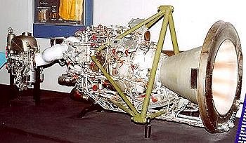 | Left: The XLR-99 rocket engine, fueled by LOX and anhydrous ammonia.
|
The XLR-99 made 339 flights between 1959 and 1968.
AMMONIA AND REFRIGERATION
Refrigeration is not of course a means of power generation- quite the reverse- but it is worth pointing out that ammonia is central to the operation of that most ingenious device the absorption refrigerator. (external link)
See also:
howstuffworks.com
Ammonia is also still very much in use as a vapour-compression refrigerant in industry.
These chaps are quite keen on it:
The International Institute of Ammonia Refrigeration
as their name might suggest...
![]()

|