This page deals with unusual bicycles powered mainly by human effort. Bicycles with other forms of propulsion, such as rockets or steam-engines, have their own pages.
There have of course been many "unusual" bicycles, and this gallery shows just a sample.

THE COMPRESSED-AIR ENERGY STORAGE BICYCLE
 |
| Left: Compressed-air energy-storage bicycle: 1902
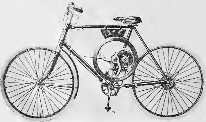
This machine was to have been driven primarily by pedal, but using a reservoir of compressed-air as an energy-storage system. It has a compressed-air motor linked to the pedal cranks, fed from the reservoir under the top tube. This is pumped up by the ten-cylinder compressor built into the rear wheel. I assume that the wheel part would have to be the compressor as otherwise it would be impossible to utilise the energy available when free-wheeling downhill. The compressed-air motor appears to be the small box above the top tube, but it is not very clear how the links to the cranks are driven.
It is however very clear indeed that the weight of the ten-cylinder wheel would be an impossible burden for a cyclist. The inefficiency involved in compressing air (the heat generated by the compression usually being lost) would also argue against this system being of any use to man or beast.
|
This sadly hopeless attempt at a worthy end was patented by William Rutherford Taylor, a cycle fitter and agent of Bo'ness, Scotland.
Back in 2005 I wrote: "It seems very unlikely that this idea even got to the prototype stage."
Well, it looks like I was wrong:
 |
| Left: Compressed-air energy-storage bicycle: 1902
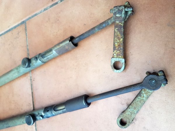
These two cylinders, attached to what are clearly bicycle cranks, are believed to be the two power cylinders of the Taylor bicycle. They were found in a shop near Bristol, England, and the shopkeeper said that was what they were. A third power cylinder was also found, and what appears to be the control valve for releasing the compressed air. Nothing else appears to remain.
Comparing the actual cylinders with those in the drawing, both have a round thing (of unknown function) and a stepped profile, which I think proves the point. The main difference is that in the drawing the cylinders connect halfway down the cranks, but the real cylinders connect to the ends of the cranks, where the pedals are fitted. The cranks here do not look wide enough to have extra holes drilled in them.
|
THE JATHO GIANT SOCIABLE BICYCLE
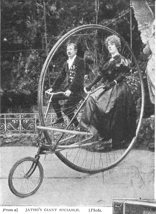 |
| Left: The Jatho Giant Sociable Bicycle: 19??
This interesting machine was designed by Mr Karl Jatho of Germany. It is not a monowheel because it has two wheels, and it is not a diwheel because it has only one main wheel.
The word 'Sociable' means that the two riders were side by side so they could talk easily. (unlike on a tandem) It looks as though it might be impossible for one person to ride it.
The big wheel was 8ft 6in in diameter. There were two pairs of pedals, each with a chain running up to a sprocket on the axle of the main wheel. The machine weighed nearly a hundredweight, (112 pounds) and cost �50 to build.
The small steering wheel at the front was 16 inches in diameter, and as the original article says "...is under the control of the male rider." Surprise, surprise.
Jatho's jacket is covered in badges; presumably the emblems of various cycle clubs.The lady on the right is Jatho's sister; she looks a bit dubious about the whole business.
Karl Jatho has a Wikipedia page, but it does not mention bicycles. It seems certain it is the same man. Jatho's main clame to fame is his early experiments with aeroplanes, managing a short hop a month before the Wright brothers made their first flight.
However, Jatho also has a German Wikipedia page, which states that he was noted for bicycle stunts before he became interested in aviation. It also tells us that the Giant Sociable weighed 40-kilograms and was built by the Gebr. Forcke factory for 2,000 Reichsmarks.
Main source: The Strand Magazine Vol XVII-4 (exact date currently unknown)
Thanks to Bernd F for additional information from German Wikipedia.
|
THE SAIL-POWERED BICYCLE
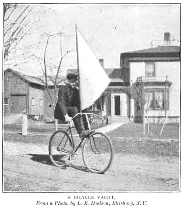 |
| Left: The Flywheel Bicycle: 19??
This sail-bike had a 10-foot mast rigidly attached to the frame 4 inches behind the handlebars. The sail was of heavy cotton cloth and was controlled in an unspecified way by the rider with a cord that ran from the foot of the mast to the handlebars. The inventor, Mr L E Hudson, recommended it to sportsmen "who are fond of excitement with just a dash of danger". More than a dash, I'd have thought.
Mr L E Hudson is unknown to Google.
Source: The Strand Magazine Vol XVII-4 (date currently unknown)
|
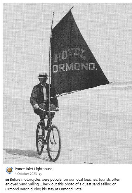 |
| Left: Sail-cycle on Ormond Beach, Ponce Inlet: date unknown
A sailbike belonging to the Ormond Hotel, at the oddly-named Ponce Inlet, a coastal town in Florida.
Note that the rider has tucked his feet up to keep them clear of the pedals; presumably the bike had no free-wheel mechanism.
|
 |
| Left: The Patterson Aeroycle: 1975
This design looks like a direct descendant of the Hudson sailbike above, with its mast attached just ahead of the handlebars. It was built by George Patterson of New Canaan, Conn, USA. The sail was controlled by gripping its bottom edge with one hand.
Patterson hoped to sell sailbikes, but there appears to have been little interest, possibly because of the $300 price tag.
There are no pedals or chain� it�s entirely wind-powered, so you could find yourself stranded if the wind drops; which seems to make for a less than practical means of transport. Mr L E Hudson above wisely retained his pedals.
There is a good deal more info on sail-bikes here.
|
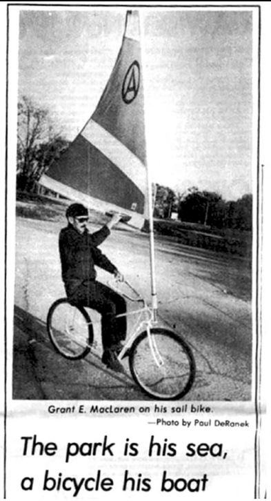 |
| Left: The McLaren sailbike: 1975?
This sailbike was built by George E McLaren of Sy Louis, apparently to Patterson's design. (above) Note the cutout in the sail so the boom can be grasped more easily.
|
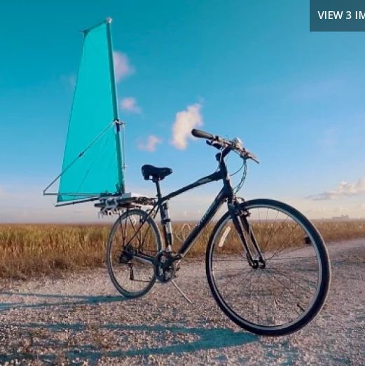 |
| Left: The CycleWing: 2025
The CycleWing has its sail at the rear, which seems more practical in terms of seeing where you are going. The CycleWing is the subject of a Kickstarter campaign.
The angle of the sail is set by an electric motor controlled by the small grey box on the handlebars. This seems like an odd decision because even if the wind is blowing, you are dependant on a rechargeable battery.
Note the pedals are retained.
There is more info here.
|
THE FLYWHEEL BICYCLE
In 1920 some misguided Frenchman (currently unknown) added a flywheel to a bicycle, apparently believing that this would reduce the power required to move it. The First Law of Thermodynamics states inflexibly that you cannot get more energy out than you put in. The only way it might be useful is if you stored energy in the flywheel while going downhill instead of using the brakes; even then very little energy is stored.
 |
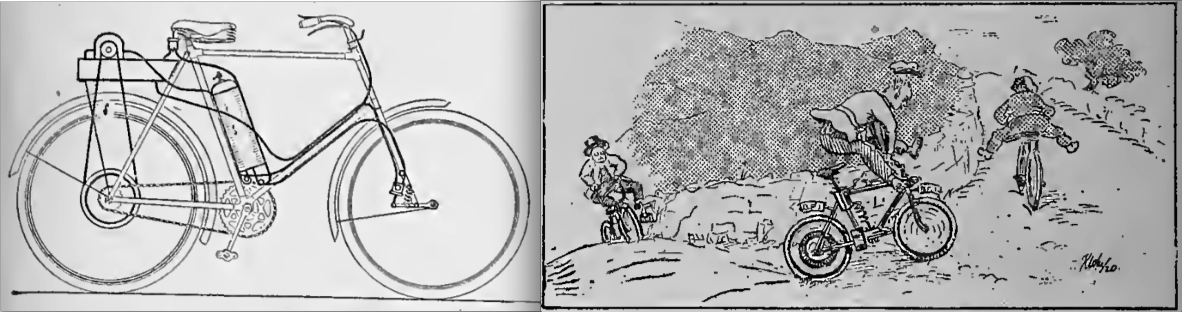
| Left: The Flywheel Bicycle: 1920
This is from the original article:
�WHY FIT AN ENGINE? BRITISH LIGHTWEIGHT manufacturers must look to their laurels if they are to keep pace with Continental developments! A French invention intended to be fitted to any form pedal cycle consists of a flywheel interposed in the pedal chain drive, its functions being controlled by a clutch. The inventor claims that his device eliminates fatigue, as an occasional stroke of the pedals is all that is necessary to keep the machine in motion, and that the gyroscopic action of the flywheel stabilises the machine. Also, of course, it is pointed out that energy is stored in the flywheel for use when needed. For the benefit of unmechanical readers, it may be stated that from the very best design of flywheel it is impossible to obtain quite as much energy as is originally put in, so that unless the roads are specially designed with a long downhill section before each slight rise, one will still have to pedal one�s cycle, with the additional weight of the� flywheel, clutch, and gear.�
|
Source: The Motorcycle 1920
|
As noted elsewhere in The Museum, ideas, even bad ones, seldom go away entirely. People are still adding fly wheels to bicycles. It is stated
here that the flywheel stores a small fraction of the energy content of a AA battery, which suggests that the weight of the flywheel would be a liability given the minimal energy storage. There is another flywheel bike by Maxwell von Stein here, which uses a continuously-variable transmission in the rear hub, linked by chain to a 6.8 kg (15 lb) flywheel from a car engine mounted in the middle of the frame. How the CVT works is currently unknown.
There is a third flywheel bike here.
THE MEIFFRET RECORD ATTEMPT BICYCLE
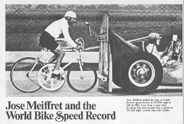 |
| Left: The Meiffret Record Attempt Bicycle: 1961
The obvious oddity here (apart from the racing car to the right) is the enormous chainwheel that almost touches the ground. This is Jose Meiffret on his way to make a world record speed on a bicycle of 115.9 mph in the autumn of 1961. He set another record of 127.3 mph in 1962; this still stood in 1972. The current record is no less than 183.931 mph, held by Denise Mueller-Korenek.
This is 'draughting' where the cyclist rides very closely behind a flat plate on the back of a car or motorcycle. It is also called motor pacing. There is a comprehensive list of cycling records (obtained under widely varying conditions) in Wikipedia. The current unpaced bicycle record is 82.8 mph (2009) which just goes to show how much assistance the draughting plate gives.
Note the roller on the rear of the draughting plate, intended to prevent catastrophe if the cyclist caught up with the draughting plate and hit it.
Source: The Complete Bicycle Book � 1972 Peterson Publishing Company
|
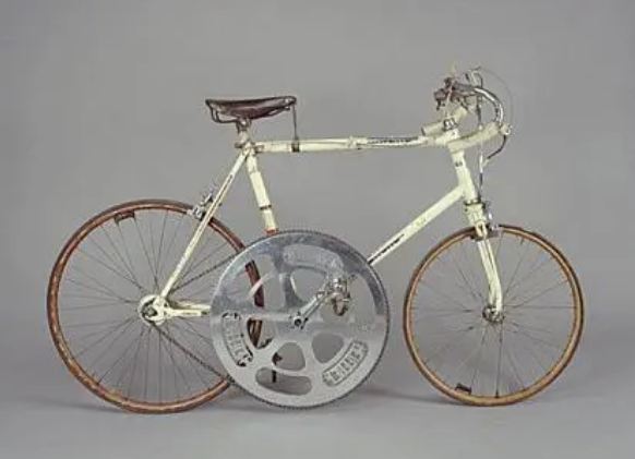 |
| Left: The Meiffret Record Attempt Bicycle: 1961
The enormous chainwheel had 130 teeth. The bike weighed 45 pounds. Note that the front forks are fitted backwards so the rider can get closer to the draughting plate.
|
THE BUMP CYCLE
 |
|
Above: The Bump Bicycle: 1920
Source: The Motorcycle 1920
|
This is what The Motorcycle said in 1920:
"AN OIL TURBINE TO BE ADOPTED as an auxiliary power unit for a bicycle:
The inventor of the bump bicycle, as it is called, has adopted a different system from our French friend�The Bump is in no sense a motor bicycle as we understand it, but is intended to be a motor-assisted bicycle�There is a cylinder attached to the saddle tube of the bicycle, provided with an� ordinary tyre valve at the top. Air is pumped into this by means of an ordinary bicycle pump to a pressure of about 15lb to the square inch.
The lower portion of the cylinder contains oil, on which a float rests, thus separating the oil from the air chambers. The pump is attached to the back of the saddle, and is operated by the saddle moving up and down, owing to ordinary undulations in in the road. It serves to pump the oil from the small reservoir over the rear wheel� the exhaust chamber, as it were� to the large reservoir, which in turn delivers it to a small Pelton wheel. This is situated on the top of the oil tank. The power is conveyed to the rear wheel by means of a chain, and the flow of oil is controlled by a lever on the handle-bars. Similar pumps can be attached to the front wheels when they are sprung. It is handled by Central Traction Ltd, 125 Wool Exchange, London, EC."
Source: The Motorcycle 1920
|
This notion makes the compressed-air bicycle above look almost practical. The energy input from the saddle would be tiny. You have to carry around a lot of extra hardware and what looks like a considerable quantity of oil. Oil is more viscous than water, and I should think the losses in an oil Pelton wheel would be horrendous. On top, whenever you compress air it gets hotter and that energy is lost unless you have super-insulation. Attempts to find out just who perpetrated this daft idea have so far failed. Grace's Guide has not heard of the Central Traction Ltd.
THE PADDLE-WHEEL PROPELLED BICYCLE
This exhibit has now been moved to the Paddle-wheel Aeroplane gallery of the Museum.
THE THRUSTPAC PROPELLOR-PROPELLED BICYCLE
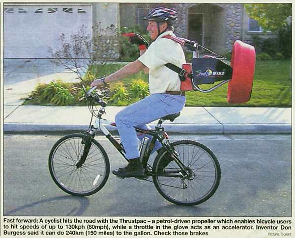 |
| Left: The Thrustpac Bicycle: 2006
I put this scary-looking concept in the bicycles gallery rather than the motorcycles gallery as the engine is attached to the rider rather than the bicycle.
For full-on propellor-driven motorcycles,
see the propellor-motorcycle gallery.
Thrustpac is a commercial operation in California; see
http://www.personalpropulsion.com
They claim it can also be used with scooters and small boats.
From the Metro newspaper (London) 8 Jan 2006
|
THE SUSPENDED MONORAIL BICYCLE
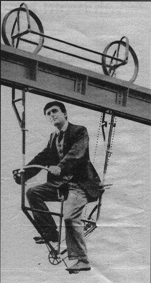 |
| Left: The Suspended Monorail Bicycle: 1892.
This is the front cover photo of "New Movement in Cities" a book on urban transport written by expert Brian Richards. He is riding on what is now identified as the Hotchkiss Bicycle Railway, which runs from Mount Holly to Smithville in New Jersey, USA. It was invented by Arthur E Hotchkiss, and built in 1892. According to one source, the idea was that you hired a bicycle and cycled along the girder track to your destination; there were a number of bicycle depots along the route. Why this would be better than cycling along a paved path I do not know. I also don't know what Mr Richards opinion of this system was, but I doubt very much if it was seriously proposed as a solution to our transport problems.
An interesting point is that the monorail bicycles were bidirectional, so they did not have to be laboriously lifted off the girder and turned around. There were handlebars at each end, for support rather than steering, and the saddle presumably swivelled.
|
More on the Hotchkiss Bicycle Railway:
Another source states that the Railway was built to allow employees to commute quickly from Mount Holly to a large factory at Smithville. The railway was not a success, the impossibility of overtaking being one reason; another was that a second track was never completed, so if riders travelling in opposite directions met, one had to pull off onto a siding. One might imagine this leading to disagreements about who had the right of way. The railway was in a severe state of disrepair by 1898 when the Mount Holly and Smithville Bicycle Railway Company (as it appears to have been known) declared bankruptcy.
Presumably the system was repaired at some point, and probably opened for recreational use; hence the modern photograph.
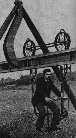 |
| Left: The Suspended Monorail Bicycle: 1892.
A contemporary picture, with a serious-looking rider skimming above a landscape apparently by Van Gogh. It is not clear just how far off the ground the bicycle is; there would seem to be no advantage in having a ground clearance of more than a foot or two.
Here the rider has the chain-drive in front of him, not behind like Mr Richards, so confirming the bidirectional nature of the bicycles. Note the supporting steelwork is hook-shaped to allow the wheels to pass.
|
ERIC STALLER'S CONFERENCE BIKE
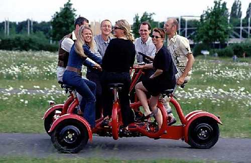 |
| Left: The Eric Staller Conference Bicycle: 2005.
This inspired creation is pedalled by seven people sitting in a circle. Steering is not however, by committee- an opportunity lost there, I feel. The chap on the extreme right is holding the steering wheel. The front of the vehicle is at the left.
OK, it's not strictly a bicycle- in fact it's a quadcycle, though the two back wheels are so close together you could, if you wanted to be difficult, argue that it was more of a tricycle than anything else. But there isn't an unusual quadcycle page (for which this machine would certainly qualify) just a conventional quadcycle page, so here it is.
|
For more info see: The Conference Bike.
THE BOOTBIKES
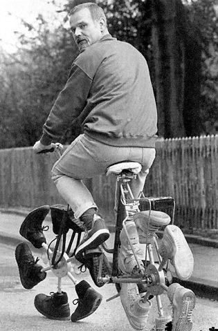 |
| Left: The BootBike
This fascinating machine looks quite practical. It would certainly eliminate the possibility of punctures.
The picture was sent to me by one of my vast network of correspondents, unfortunately with no accompanying details at all. To begin with, close examination has persuaded me that it is a real machine and not just a Photoshop job.
The rider is on the right side of the road rather than the left, so it comes from continental Europe rather than Great Britain. I suspect its origin is German.
If anyone can offer any more information I would be most grateful.
|
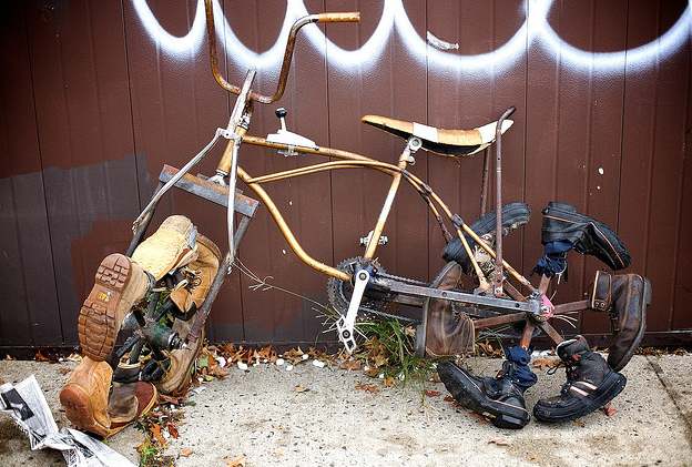 |
| Left: Bootbike at Bike Kill 08
Call me picky, but the boots on the front wheel seem to be the wrong way round. See the picture above.
|
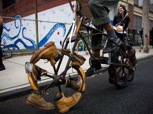 |
| Left: Bootbike at Bike Kill 08
Another view of the bootbike. Bike Kill is an annual Tall and Mutant Bike event organized and hosted by members of the Black Label Bike Club. The event is held in Brooklyn at the end of October.
It provides an enormous number of examples of eccentric bicycles.
|
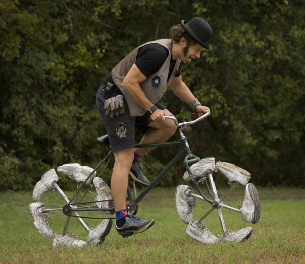 |
| Left: Plimsoll-bike
|
 |  |
| Left: Bootbikes
I have no information at all on these bootbikes, just the images. The one on the left appears to be devoid of brakes; clearly rim-braking isn't going to work.
Hub brakes should be OK, but I don't see any sign of them here.
There seems to be a consensus that six spokes and six boots should be used per wheel.
|
WHEEL-SEGMENT 'BICYCLE'
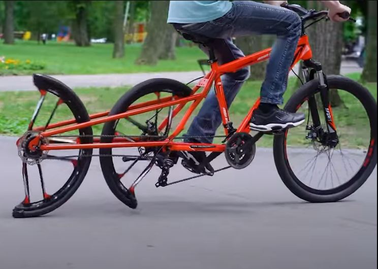 |
| Left: Wheel-segment 'bicycle': 2022
A whole new approach to bicycle design; I say bicycle, because 1 wheel + 1/2 a wheel + 1/2 a wheel= 2 wheels. Here the rear wheel has been split into two half-wheeels, turning at the same speed so you get a rideable bike.
You can see an excellent video of this machine on YouTube. Pointless perhaps, (the video gives no clue as to the motivation) but certainly ingenious and fun.
|
HUBLESS BICYCLE
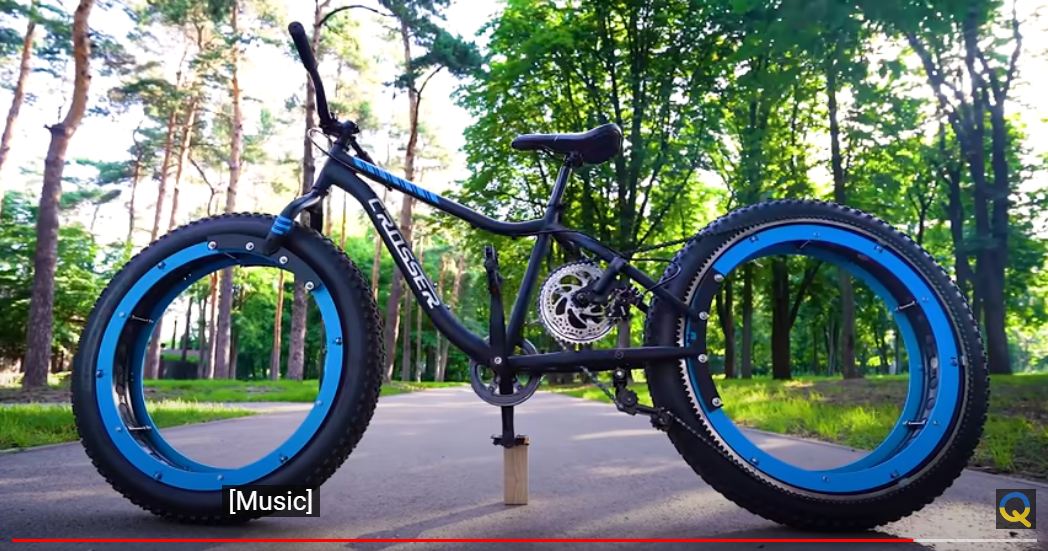 |
| Left: Hubless bicycle: 2021
This is deeply ingenious, but as many people have noted , the gear ratio for pedalling looks all wrong. You need a step-up in speed for a bicycle, not a step-down.
You can see the video on You Tube.
|
SPRING-WHEEL BICYCLES
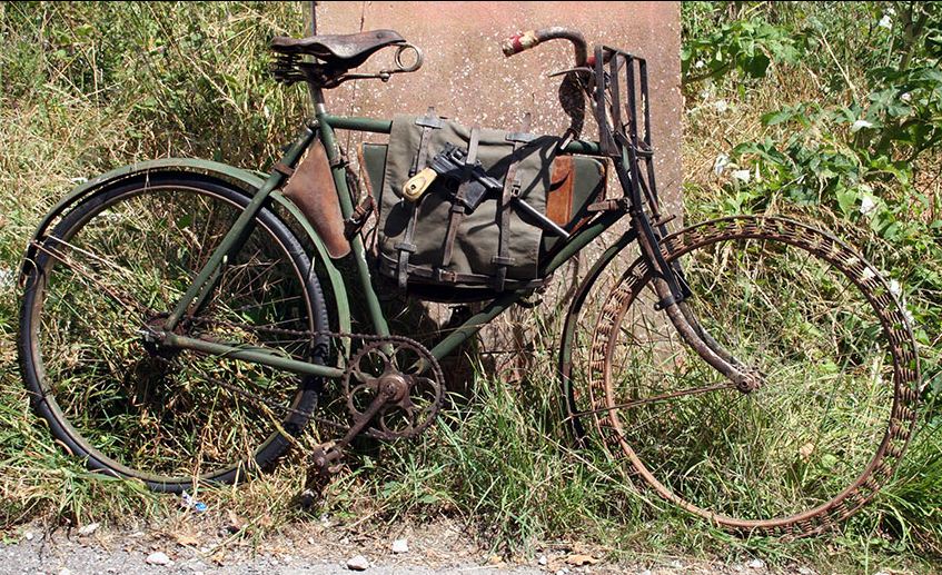 |
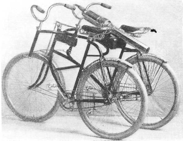
| Left: Spring-wheel bicycle: 1905
There are two main reasons for adopting the extra complications and weight of a sprung bicycle wheel.
1) To secure total immunity from punctures. A downside is that the weight of the wheel in considerably increased by all the extra metal.
2) If rubber for tyres is in desperately short supply.
This is a 1905 Victoria Herrenrad; ('Herrenrad' is German for 'Gent's Bicycle') these were used in large numbers in WW1. Note the 1916 Mauser C96 �Broomhandle� Semi-Automatic Pistol strapped to the bag.
There is more info here.
|
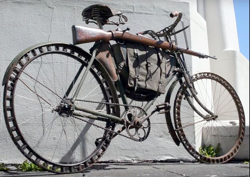 |
| Left: Spring-wheel bicycle: 1905
This example has both wheels sprung.
The rifle is a Mauser GEW-88.
|
LE CYCLONE BICYCLE
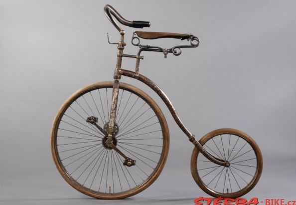 |
| Left: Le Cyclone Chainless Bicycle: 1893/94
This bicycle is actually relative conventional compared with some of the creations in this gallery. The pedals are geared-up to the front wheel by two pairs of gears. While it is a very compact arrangement, it has the snag that you are pedalling a wheel that has to be turned for steering; it must have made for awkward pedalling.
The position of the saddle seems odd. What's even odder is the apparent total absence of brakes.
Le Cyclone was manufactured by Milders Fils of France, (who are unknown to Google) over a relatively short period, so it does not seem to have been successful. I blame the pedalling arrangements.
|
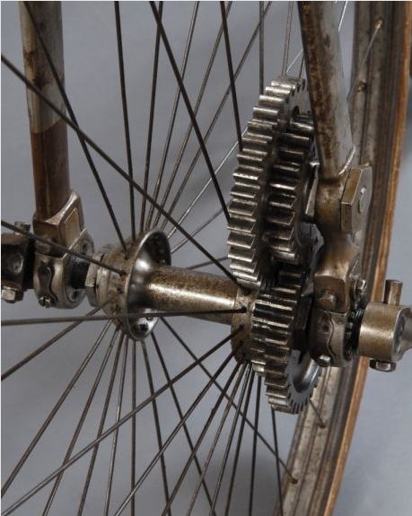 |
| Left: Le Cyclone Chainless Bicycle: 1893/94
The gear to the lower right must be on a sleeve that goes over the axle; it meshes at 1:1 with the gear above it. The gears on the left provide the step-up ratio and the lower of the pair is fixed to the axle.
|
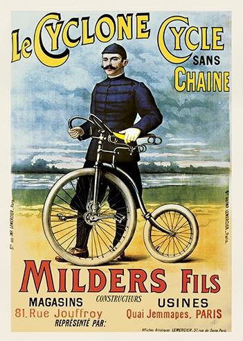 |
| Left: Le Cyclone Chainless Bicycle advert: 1893/94
This image is all over the internet, and it's about all you get if you Google 'Le Cyclone'.
|
FIRE BRIGADE BICYCLES
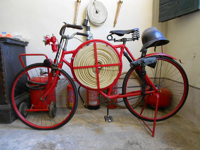 |
| Left: Fire Brigade bicycle: 19??
This bicycle has a special frame that allows it to carry a hose-reel.
Note the antique fireman's helmet casually tossed upon a support coming up from the rear mudguard, and the fireman's axe carried beside the rear wheel.
|
MILITARY BICYCLES
I have not overlooked the fact that strictly speaking, the vehicles in this section are tricycles and quadracycles rather than bicycles; for the moment at least I am keeping all the militiary stuff together here.
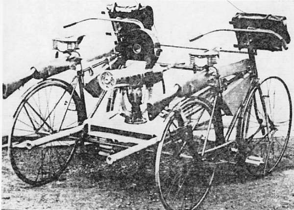 |
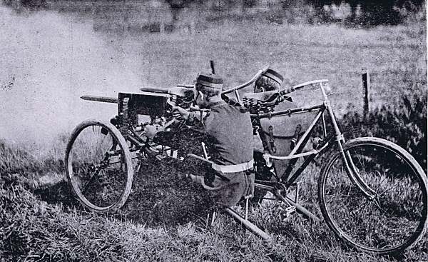
| Left: The first machine-gun bike: 1891
This is the first known bicycle mounting of a machine gun. The 26th Middlesex Cycle Regiment displayed the firing of a machine gun from this cycle carriage at the English Easter Manoeuvres of 1891. There were snags; the vehicle wighed 96 pounds, had solid rubber tyres, and two men could not pedal it uphill. It was hard to reach a few miles per hour even on the flat, and two more bicycles had to be hooked up at the front to help tow it.
Histories usually refer to the weapon as a Maxim gun, but the photograph is actually of a 6-barrel Bulldog-model Gatling gun, an 1883 design fed from an Accles drum magazine holding 104 rounds. These magazines proved too fragile for field use, and were withdrawn. Many thanks to Andreas Marx and Charles Wine for identifying the gun.
Two normal bicycles are joined by cross-members. The handle-bars are joined by a rod to keep the front wheels in alignment, and note the two rifles carried in holsters on the top tubes.
|
 |
| Left: The Pope tricycle cannon: 1895
This unlikely-looking machine was built by the Pope Manufacturing Company in the USA; one of the major bicycle makers. A light mountain cannon is mounted facing rearwards on a tricycle frame pedalled by two men sitting side by side, each with a set of handlebars linked to the front wheel. All that is known of its history is that it was once ridden in a Brooklyn parade. The tricycle frame was later used to mount a forward-firing machine gun.
Given that there appear to be no arrangements to absorb the recoil of the cannon, and no provision for carrying ammunition, this appears to be a publicity stunt rather than a proper attempt to develop pedal-powered artillery. However Albert Augustus Pope was seriously engaged in trying to sell military bicycles to the US Army at the time.
|
And just in case you thought nobody would ever do anything so daft again, consider the Italian Vespa scooter modified to carry a M20 75 mm recoilless rifle. While the lack of recoil made it theoretically possible to fire the gun from the scooter, in practice it was to be removed and mounted on a tripod. This creation was used in the 1950s by the French Airborne Forces, being dropped in pairs by parachute.
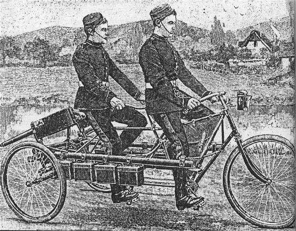 |
| Left: The Vickers machine-gun tricycle: 1901
This two-man machine-gun tricycle was built by the armaments firm of Vickers Sons & Maxim in 1901. It carried two machine guns and 1000 rounds of ammunition, the latter in the small boxes suspended from the large side tubes, which hinged downward to brace the carriage against the recoil. It weighed 374 pounds, including guns and ammunition, but not including riders, and could not be pedalled up a slope. On the other hand, both machine guns could be put into action in two minutes, though it is not obvious why it would take that long.
The second gun is just visible below the breech of the nearer gun.
|
Vickers produced this press release:
"The bicycle artillery corps is a body of recent creation which seems to be destined for a great future. In fact, it is now in a fair way of doing reconnoissance duty in place of the cavalry. How much superior, indeed, is a bicyclist to a horseman. He is always ready to start immediately, while the latter has to wait to harness and saddle his steed. Then, again, the bicycle is faster than the horse, and requires less care; and the fact that no food is needed constitutes an appreciable advantage in a campaign in which so many difficulties are met with in the way of procuring forage. It is true that the bicycle can be used only upon roads, but in France and Germany the byroads, large and small, are so accessible that the use of it is capable of being made general."
"Such considerations have led the large English house of Vickers, Sons & Maxim to devise a machine gun tricycle, which we represent in the accompanying engravings. Two light Maxim guns are mounted upon the tricycle, the weight of which is 120 pounds, while that of the two guns is 54, that of the tripods 106, that of the spare pieces 8, and that of the 1,000 cartridges, with their case, 86. This constitutes a total weight of 374 pounds, to which is to be added that of the two men who ride the vehicle. It seems that such a tricycle is capable of running at a high rate of speed upon a level. Upon up-grades, however, it is necessary to dismount and push the machine."
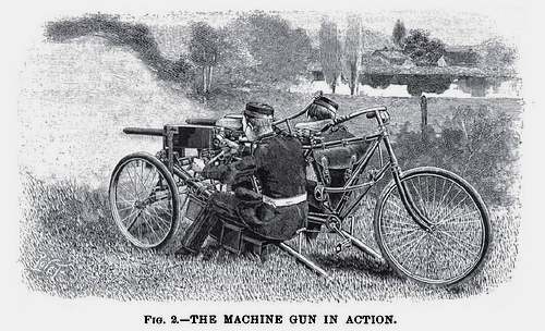 |
| Left: The Vickers machine-gun tricycle: 1901
The two-man machine-gun tricycle in action, with both guns firing simultaneously. The side-tubes have been lowered and dug into the ground- for some reason they are described as "tripods" in the press release above. The two of them weighed 106 pounds, which was nearly a third of the weight of the vehicle, and one wonders why they could not have been made lighter.
|
 |
| Left: The Vickers machine-gun tricycle: 1901
This is the original photograph from which the illustration above was made.
|
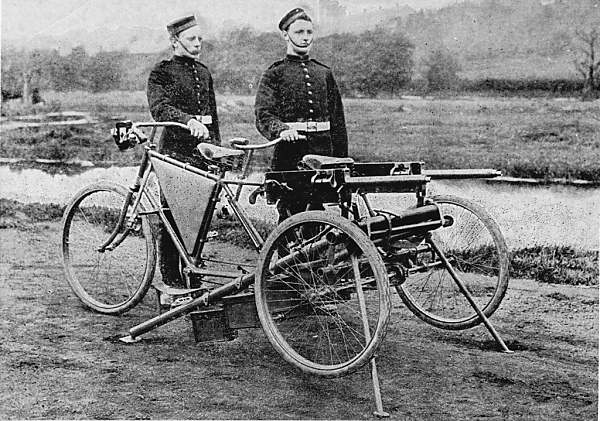 |
| Left: The Vickers machine-gun tricycle: 1901
The two-man machine-gun tricycle ready for action. Applying the steadying tubes raises the rear wheels off the ground.
|
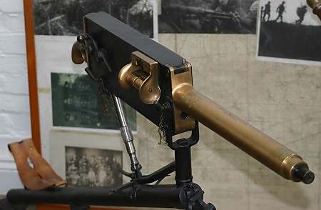 |
| Left: The Light Maxim Gun
As carried by the tricycle. Note the pistol-grip at the rear for firing. Calibre .303
|
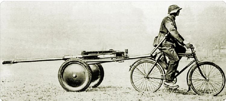 |
| Left: Swiss towed anti-tank rifle: 1941
Here a semi-auto anti-tank rifle is being pulled by a Swiss MO-05 bicycle ridden by an infantryman. The gun is a 24 mm Tankbuchse 41, which fired a powerful 24x138 mm round. Thanks to an effective muzzle brake, the recoil was acceptable. The gun used a six-round magazine.
There is more info here
|


