Rotary Steam Engines: Page 6
|
| |
Gallery opened Aug 2002
Updated: 30 Dec 2024
The Spiro Engine updated here.
|   
| |
CONTENTS OF THIS PAGE
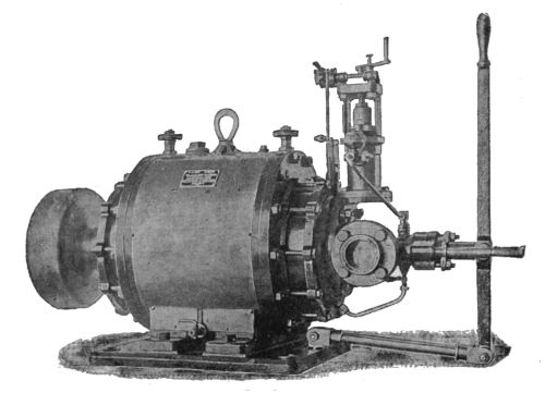
A COMPOUND ROTARY ENGINE: 18??
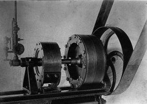 |
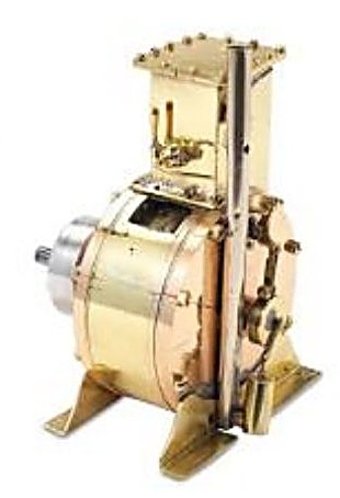
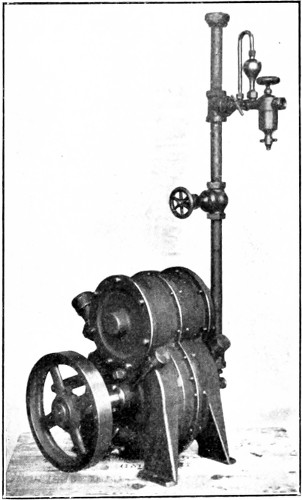
| Left: A rare photo of a compound rotary engine.
It looks like steam comes in from the left, via the vertical pipe fitted with a control valve, and passes to the small casing through the shaft. Presumably it then passes to the larger casing on the right in the same way. There is no sign of any exhaust pipework.
I have to confess that I have lost my notes relating to this photo. I know it came from the web, and I have a vague recollection it was in an American museum. If anyone can identify it or feels I have infringed their copyright, then please get in touch.
|
ANOTHER ANONYMOUS ROTARY ENGINE: 18??
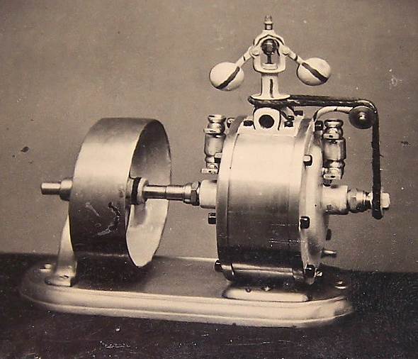 |
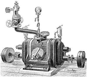
| Left: Rotary engine of unknown origin
This old tintype photograph was sent to me by Jack Mord in June 2012, in the hope that I could identify the engine. I couldn't.
It looks as if the steam inlet is the dark hole just below the flyball governor, which no doubt operated a throttle valve. Presumably the exhaust port is on the other side. The two attachments on the side of the casing appear to be cup-type lubricators. I'm not entirely happy with the drive to the governor- it looks as though the drive cord would come under a lot of strain passing over those tiny pulleys.
If anyone can identify this engine I would be very pleased to hear about it. This seemed as good a place as any to put it.
|

THE CROSS ENGINE: 1881
 |
 |
| Left: The Cross rotary engine: 1881
This engine was patented by David L Cross of Austin, Texas. It's mode of operation is not easy to deduce even with the patent to hand, but looking at Fig 3 there is an eccentric rotor B with sliding flaps that are moved out of the way by a cylindrical roller C2, just in time to avoid hitting the abutment C'. It is hard to imagine this as a leak-free process.
Steam distribution is by two rotary valves oscillated by an eccentric E on the engine shaft. The valve operation can be altered by movable pins so that the engine can be stopped or reversed.
Googling "cross rotary engine" produced some intersting results. From the Tucson British Car Register:
"Prewar production at Toworth amounted to some thirty cars, the majority of the 1.5 litre type. In addition, however,
a rakish little coupe was constructed in 1938 on a modified single-seater chassis originally designed by Halford and
fitted with an unsuccessful Cross rotary engine. This car, now fitted with a 1600cc Triumph engine, never saw
production."
And from The New Zealand Rolls-Royce & Bentley Club (Inc):
"As you know, speaking as the only private owner of a Cross Rotary engine I have a weakness for odd engines."
Note these engines are not said to be steam powered.
I suspect they refer to engines fitted with The Cross Rotary Valve.
From US patent 244,558, granted 19 July 1881
|
THE WIGMORE ENGINE: 1881
 |
| Left: Patent model of the Wigmore rotary engine: 1881
This engine was introduced by William Wigmore of Philadelphia, Pennsylvania. It was claimed to run on a mixture of air, gas, and water, the later being turned to steam by a water-jacket around the engine. The air and gas and some point exploded, but confusingly the patent text says that the air may be cut off once the engine has heated up.
The engine itself looks like typical eccentric-cylinder-with-vanes job.
US patent 249,214 of Nov 1881
|
 |
| Left: Patent drawing of the Wigmore rotary engine: 1881
H is the water-jacket that boils the water. F is a water-pump driven by an eccentric from the output shaft; the same eccentric drives the valve K on the top of the cylinder.
From US patent 249,214 of Nov 1881
|
THE DOLGOROUKY ENGINE: 1882
 |
| Left: The Dolgorouky rotary engine.
The Dolgorouky engine stands out because an (unknown) quantity were built, and it did a useful job of driving electrical generators for some time, at least. We also know quite a lot about the inventor, Prince Alexis Sergeyevitch Dolgorouky. I found an actual example in the Technical Museum at Vienna.
Therefore the Dolgorouky engine now has its own page.
|
THE HODSON ROTARY ENGINE: 1882
 |
| Left: The Hodson rotary engine.
The French journal Nature (1882/2) described this machine as a "Moteur Rotatif de Grande Vitesse" It was stated that the engine could run effectively between 25 and 2000 rpm.
It was noted by Nature that rotary steam engines, having been generally rejected at an earlier date due to their inefficiency, were now being given a second chance because of the desirability of driving electrical generators directly and at high speed. As we now know, they still failed to find a long-term niche, partly because they still had all the old problems, exacerbated by higher speed, and because the advent of the steam turbine was very close.
At the Exhibition of Electricity at the Crystal Palace in London, they reported that the Hodson engine was seen driving generators by Brush, Gramme, and Siemens.
Even at this late date rotary engines were still being designed with rotors that smacked into hinged abutments as they whizzed round. This would seem to be particularly inappropriate for a high-speed machine, and it would be interesting to know how long part A would last at 2000 rpm.
Note also the line-contact between A and rotor B, which made any hope of proper sealing futile...
From the French journal Nature 1882/2
|
 |
| Left: The Hodson rotary engine.
The Hodson engine would not have given anything like a uniform torque, and is therefore fitted with a sizable flywheel. Note the fly-ball governor and the lubricator on top of the cylinder.
From the French journal Nature 1882/2
|
THE L J WING ROTARY ENGINE: 1882
 |
| Left: The L J Wing rotary engine: 1882
This patent was taken out by Leander J Wing of Boston in 1882. Here there are two engines mounted on a common shaft, presumably to steady the torque.
This is another engine where 'moving abutments' get out of the way of pistons going round inside the cylinder, just in time. They consist of two semi-circular doors that clap together to close off the steam space, driven by cams S, S at each end of the main shaft, via rocking arms S', S'. It is not obvious why so many were convinced that such a ramshackle business could provide effective steam sealing.
There are suggestions on Google of a book or booklet called 'L J Wing's improved rotary engine', published in 1881. So far no accessible version has been found.
From US patent 259,964 of June 1882
|
 |
| Left: The L J Wing rotary engine: 1882
Here can be seen the toroidal space in which the pistons go round, and the 'moving abutments' N, N that clap together. The engine was designed to be reversible.
The main business of L J Wing was launch engines. The company was founded by Levi J Wing in 1875 in Jersey city, NJ, and one of their first projects was this rotary engine; all that is known is that it "was not successful". I imagine not, given the mechanical diffculties.
In 1888 Wing took out US patent 607,580 for a four-stroke IC engine; it was of unusual format with the cylinders upside down and with piston rods driving a horizontal member that went up and down and drove the crankshaft (which was under the cylinders) via a connecting rod at each end. There is more information on Wing engines here.
From US patent 259,964 of June 1882
|
 |
| Left: The L J Wing rotary engine: 1882
This sheet of the patent shows the reversing valve in Figures 19 and 21, the latter being somewhat reminiscent of a multi-armed Aztec deity. In the cylinder Y slides the piston valve shown at Figures 20 and 24. Reversing also involves the simultaneous operation of the sliding plate a in Figure 22, which operates four valves through the four sector gears. The details of this given in the patent text are long and complicated, and I am not going to reproduce them here.
From US patent 259,964 of June 1882
|
THE GOLDSCHMITT ROTARY ENGINE: 1883
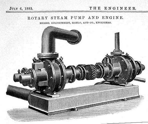 |
| Left: The Goldschmitt rotary engine: 1883
This engine is confusingly coupled to a pump of the same topology, making it hard to work out which is which.
Why are they are coupled through helical gears that appear to be the same size? Because the direction of rotation has to be reversed to make the pump work?
From The Engineer for 6 July 1883
|
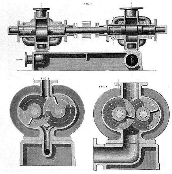 |
| Left: The Goldschmitt rotary engine: 1883
This shows that the internals closely resemble the The Dolgorouki Engine (1882) and the Behrens Engine (1886).
The approach has the advantage that it avoids line-contacts between rotor and casing that would make proper sealing virtually impossible. It looks like one of the more promising engine geometries.
From The Engineer for 6 July 1883
|
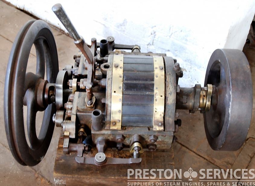
THE OUTRIDGE ROTARY ENGINE: 1885?
This is a rare example of an existing rotary steam engine. In fact you can buy it. It is for sale at: Preston Services. They say that it was built as a steam-launch engine to Outridge's patent in the mid 1880's, but do not identify the patent.
My attempts to find the Outridge patent have so far been a dismal failure. But I did find US patent 93,221A (Steam valve) which suggests that Joseph E Outridge of Newport, in the Isle of Wight, England, may be our man.
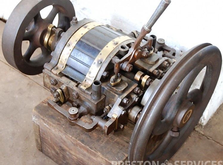 |
| Left: The Outridge rotary engine: 1885?
Here we have a relatively small casing, plus two massive flywheels. As for the Hodson engine above, this suggests problems with non-uniform torque. The lever works valves on either side of the main shaft, and this is almost certainly a forward/reverse control. On each side there is a lever which pushes on a rod going through a stuffing-box, which may operate steam inlet valves; how this lever is driven is not clear.
I consulted Bill Todd, and he says: "That Outridge engine is neat :-) It looks like it has a cam like rotor (to push the vane/abutments out) and an external cam to close the vanes and push them against the rotor. I'm sure it'll be similar to any number of flying abutment engines."
|
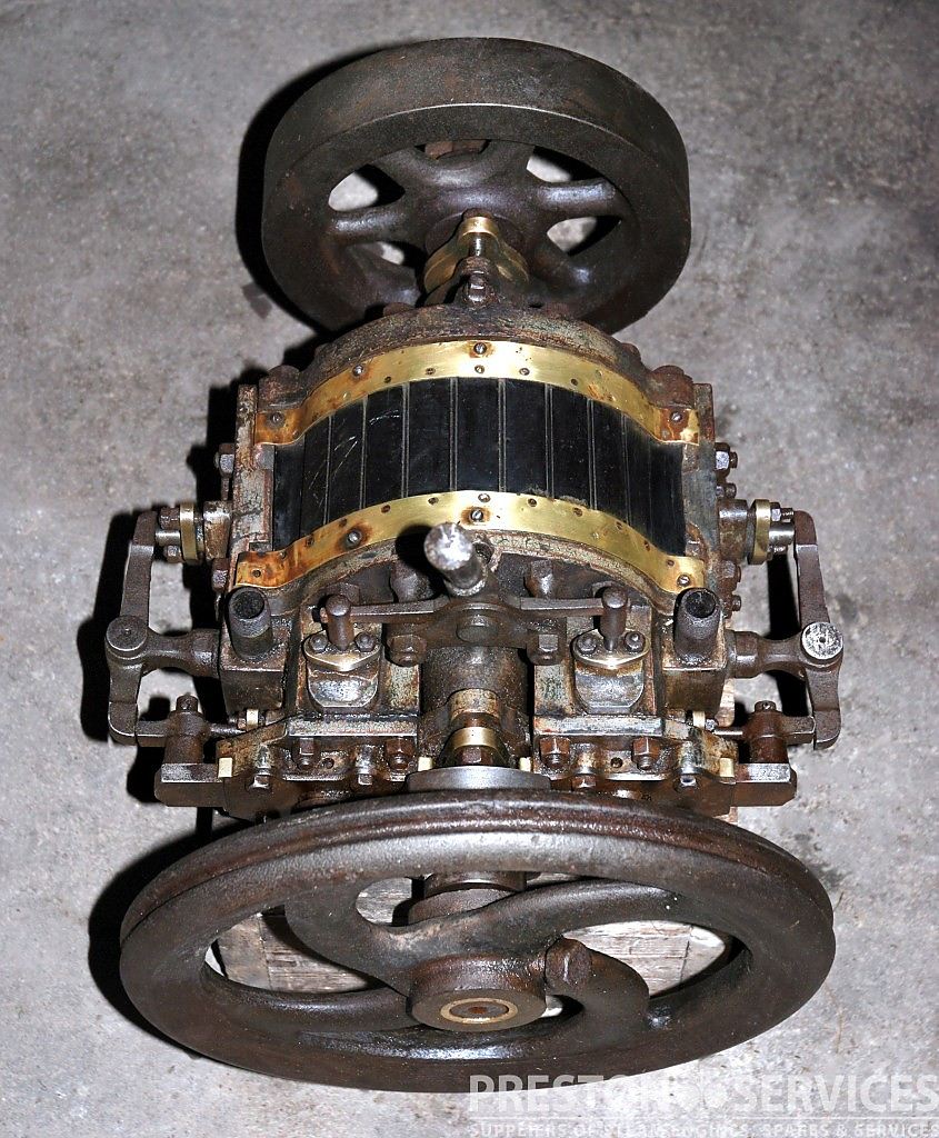 |
| Left: The Outridge rotary engine: 1885?
This top view gives a better idea of what is presumably the valvework. At extreme left and right are two rocking levers with a central pivot that is fixed to the engine body. (see picture above) The levers therefore must be driven from the end nearest the camera, but it is not at all clear how.
Note the two pipes facing upwards. Presumably they were for steam inlet.
|
 |
| Left: The Outridge rotary engine: 1885?
This side view reveals a cam and two follower-rollers mounted just behind the flywheel on the left. Exactly how they drive the two side levers remains obscure.
|
THE HODGES ROTARY ENGINE: 1885
 |
| Left: The Hodges rotary engine: 1885
The three-lobed rotor B has two hinged parts D bearing on its surface so as to make a 'seal' but since it is a line seal it won't be steam-tight at all. The hinged parts are joined by rods G with an adjustment nut H, the profile of the rotor presumably being shaped to make this arrangement kinematically viable. The spindles L' work the reversing valves.
This was not Mr Hodges' first patent; he previously was granted No 271,549 in January 1883. Of this he says: "Experience has shown that the anti-friction rollers in that device could not be made to fit as tightly as desirable in their places, so that on the reciprocation of the gates the rollers are thrown more or less violently and noisily against the steam-chest. It was also not practicable to pack the outer ends of said gates where they passed into the steam-chest, so that they would not soon wear and cause leakage.'
Mr Hodges clearly had practical experience of the sealing problems faced by rotary engines; it seems very likely that this design was actually built.
Hodge's engine is unknown to Google, but searching H F Hodges brings up a US Navy transport ship named after US General Harry Foote Hodges. During his army career he was involved in engineering, I and I thought this might be a rare case where we could track down the inventor, but... the patent was granted to a Horace F Hodges. Dammit.
This engine was previously described in error as the Ogden engine; that has now been added to this gallery and can be seen on Page 9.
From US patent 323,038 granted 28 July 1885
|
 |
| Left: The Hodges rotary engine animated: 1885
Grateful thanks to Bill Todd for another fine animation.
Bill tells me that from the patent drawing it looks like Hodges intended his rotor to have a Reuleaux shape with curvature giving it a constant width; Bill's rotor is a triangular shape with straight sides so there's some interference, ie overlapping of solids.
|
THE FIELDING & PLATT ENGINE: 1885
 |
| Left: The Fielding & Platt rotary engine: 1885
The Fielding & Platt company mostly concentrated on hydraulic machinery, especially hydraulic riveters on the Tweddle Principle, though they also made oil engines.
This model engine, which is held in storage by the Science Museum, London, is believed to be their only excursion into making steam engines.
|
 |
| Left: The Fielding & Platt rotary engine: 1885
This shows how the two pairs of cylinders are interleaved, and makes it much easier to understand what is going on. There is no way to vary the steam admission cutoff for expansive working.
This magnificent animation is by Bill Todd.
|
| Left: The Fielding & Platt rotary engine: 1885
The Scientific American Supplement No. 497, for 11 July 1885, had this to say about it:
IMPROVED HIGH-SPEED ENGINE
This engine, exhibited at South Kensington by Fielding and Platt, of Gloucester, consists virtually of a universal joint connecting two shafts whose axes form an obtuse angle of about 157 degrees. It has four cylinders, two being mounted on a chair coupling on each shaft. The word cylinder is used in a conventional sense only, since the cavities acting as such are circular, whose axes, instead of being straight lines, are arcs of circles struck from the center at which the axes of the shafts would, if continued, intersect. The four pistons are carried upon the gimbal ring, which connects, by means of pivots, the two chair couplings.
Fig. 10 shows clearly the parts constituting the coupling, cylinders,
and pistons of a compound engine. CC are the high-pressure cylinders; DD
the low pressure; EEEE the four parts forming the gimbal ring, to which
are fixed in pairs the high and low pressure pistons, GG and FF; HHHH
are the chair arms formed with the cylinders carrying pivots, IIII,
which latter fit into the bearings, JJJJ, in the gimbal ring. Figs.
1, 2, 3, 4 show these parts connected and at different points of the
shaft's rotation. The direction of rotation is shown by the arrow. In
Fig. 1 the lower high-pressure cylinder, C, is just about taking steam,
the upper one just closing the exhaust; the low-pressure pistons are at
half stroke, that in sight exhausting, the opposite one, which cannot be
seen in this view, taking steam.
In Fig 2 the shaft has turned through one-eighth of a revolution; in
Fig. 3, a quarter turn; Fig. 4, three-eighths of a turn. Another eighth
turn brings two parts into position represented by Fig. 1, except the
second pair of cylinders now replace the first pair. The bearings, KL,
support the two shafts and act as stationary valves, against which faces
formed on the cylinders revolve; steam and exhaust ports are provided in
the faces of K and L, and two ports in the revolving faces, one to each
cylinder. The point at which steam is cut off is determined by the
length of the admission ports in K and L. The exhaust port is made of
such a length that steam may escape from the cylinders during the whole
of the return stroke of pistons.
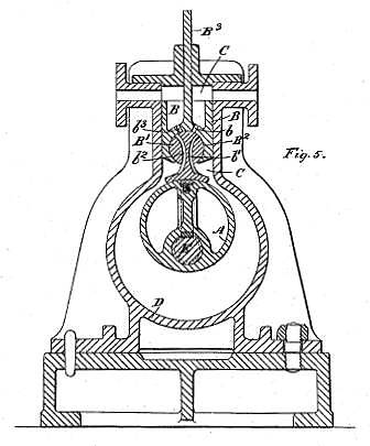
Fig. 5 shows the complete engine. It will be seen that the engine is
entirely incased in a box frame, with, however, a lid for ready access
to the parts for examination, one great advantage being that the engine
can be worked with the cover removed, thus enabling any leakage past the
pistons or valve faces to be at once detected. The casing also serves to
retain a certain amount of lubricant. The lubrication is effected by means of a triple sight-feed lubricator,
one feeder delivering to steam inlet, and two serving the main shaft
bearings.
Figs, 6 and 7 are an end elevation and plan of the same engine. There is
nothing in the other details calling for special notice.
Figs. 8 and 9 show the method of machining the cylinders and pistons,
the whole of which can be done by ordinary lathes, which is evidently a
great advantage in the event of reboring, etc., being required in the
colonies or other countries where special tools are inaccessible.
Figs. 11 and 12 are sections which explain themselves.
|
This description indicates that the engine is more of an axial steam-engine than a rotary engine, but it goes here for the time being at least. The engine can be compared with the Tower Spherical Engine. Note that the engine in the Scientific American diagrams has a quite different casing and general appearance from the Science Museum model. It looks more like a full-size prototype, and so it appears at least two examples of the engine were built.
No other information on this engine has been found so far
|
|
THE BEHRENS ENGINE: 1886
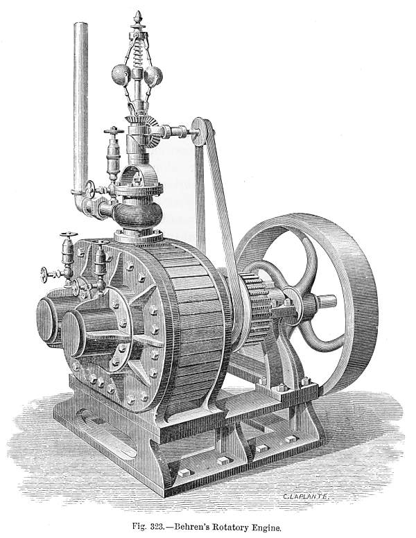 |
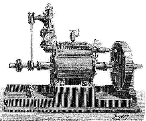
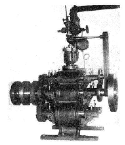
| Left: The Behrens rotary engine: the exterior.
This engine was introduced by Henry J Behrens, and patented in the USA in 1866. It also has a hefty flywheel. As with the Hodson engine, there is a fly-ball governor on top of the casing, which controls the steam coming in via the vertical pipe at top left.
There are three conical-shaped things fitted with valves. I am not sure, but they are probably lubricators. The rotor synchronising gears can be seen between the governor drive-belt and the flywheel.
Deschanel remarks, (on rotary steam engines in general) "Hitherto... the results obtained by this method have not been encouraging." However, he describes the Behrens engine as "one of the best examples."
From Elementary Treatise on Natural Philosophy by Deschanel, trans J D Everett. Pub 1886 by Blackie & Son. Vol 2, p505
|
 |
| Left: The Behrens rotary engine: the internals.
The two C-shaped bits marked c, c' stay still while the scimitar-shaped rotors go
round in opposite directions, synchronised by gears outside the casing.
B is the steam admission pipe, while the exhaust is at D.
The Behrens engine has the advantage that it avoids line-contacts between rotor and casing that would make proper sealing virtually impossible. It looks like one of the more promising engine geometries.
From Elementary Treatise on Natural Philosophy by Deschanel, trans J D Everett. Pub 1886 by Blackie & Son. Vol 2, p506
This drawing is clearly derived directly from the patent drawing below.
|
 |
| Left: The Behrens rotary engine: animated.
Bill Todd points out that this raises the question: how do the two rotors connect to the output shafts? See below...
Another superb animation by Bill Todd, who is unquestionably the leading rotary-steam-engine animator in the world.
|
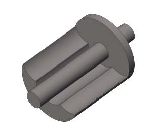 |
| Left: The Behrens rotary engine: one of the rotors. (speculative)
How do the two C-shaped rotors connect to the output shafts?
Bill says: "As far as I can see, the only way would be to add a disk to the
end of each rotor (see drawing) then recess these disks, one into the front
cover and one into the back cover, so the opposing rotors could sweep
across the disks, flush with inside of the cylinder."
Sounds good to me.
Drawing by Bill Todd.
|
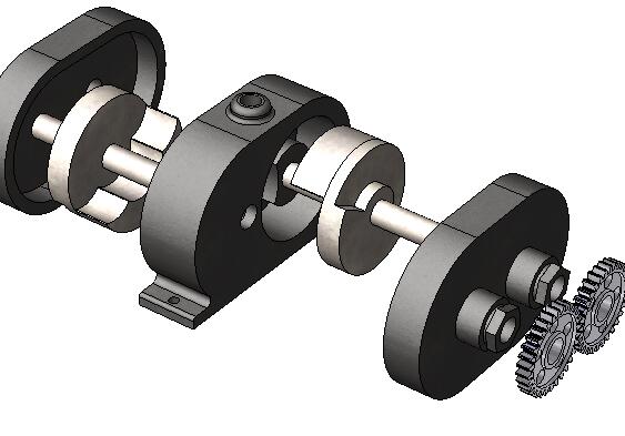 |
| Left: The Behrens rotary engine: exploded view
Note the addition of balance weights to the rear of each rotor disc.
Drawing by Bill Todd.
|
 |
| Left: The Behrens rotary engine: patent drawing
Fig 1 from US Patent No 53,915 dated 10th April 1866.
|
 |
| Left: The Behrens rotary engine: patent drawing
Plan view showing the synchronising gears and balance weights on the back of the rotor discs.
Fig 2 from US Patent No 53,915 dated 10th April 1866.
|
 |
| Left: The Behrens rotary engine: patent drawing
Variation on a theme; Mr Behrens claims that the engine is balance by having two "pistons", and that "one upon each shaft is acted upon during one-fourth part of a revolution". He is presumably referring to the dynamical balance of each shaft; a symmetrical arrangement as shown here would remove the need for balance weights on the rotors.
Fig 3 from US Patent No 53,915 dated 10th April 1866.
|
Development of the Behrens engine was clearly continuing in 1868, for in that year another US patent (No 77,373 dated 28th April 1868) showing an engine very similar to that in the first patent, was taken out by a Dexter D Hardy, and assigned to Behrens.
It is uncommon to come across an advertisment for a rotary steam engine, but I did so today, (12 May 2013) in a pamphlet on sale at a London book fair. Regrettably it was priced ay Ł45 for a few pages so I did not succumb to the temptation to buy it. You will have to make do with the following description.
The pamphlet, dated May 1872, was produced by Appleby & Co, of Renishaw Ironworks. Most of the products offered were conventional force pumps, but on the inside front cover was an advert for the Behrens motor/pump. These were being sold through Appleby Bros, an apparently separate concern trading from Southwark, in south London. An illustration showed a Behrens engine driving a Behrens pump, with two very substantial shafts between them connected by gear-wheels of equal size. It is claimed that the pump is suitable for shifting just about any fluid. Six testimonials are supplied, one of which, judging by the name of its author, came from France. All the testimonials state that the Behrens engine and pump were throughly satisfactory and had been working in their installations for some time. No prices were quoted.
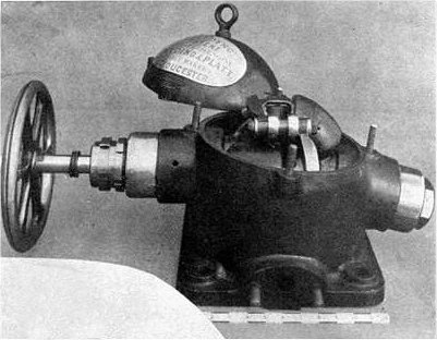
THE HUBBARD CONCENTRIC PISTON ROTARY STEAM ENGINE: 1888
 |
| Left: The Hubbard engine: 1888
This engine was patented by George W Hubbard of Windsor Vermont. The patent text talks about "improvements to concentric-piston steam-engines" as if that was a well known type of engine at the time; as far as the Museum Staff can determine, this was not the case.
The patent text runs to more than four pages and is not an easy read, but this basically seems to be a pursuing-piston engine. In this diagram the actual steam cylinder is at the right, bisected by the line x-x, while the crank mechanism that gives the pursuing-piston action is in the centre, marked by the line y-y. I suppose any pursuing-piston engine must have the two pistons rotating about the same centre, and so they are inherently 'concentric'.
|
 |
| Left: The Hubbard engine: 1888
Figure 3 shows multiple ports for steam admission and exhaust, put in and out of action by the horizontal sliding valve.
Steam is admitted through ports s t u v w, which can be closed off sequentially by the sliding valve to determine the admission cutoff. The exhaust ports are p o n m l.
Despite the symmetrical look of the engine, the patent text states that it is not reversible without modification, presumably of the sliding valve. It is therefore puzzling that the exhaust ports are the mirror-image of the admission ports.
|
 |
| Left: The Hubbard engine: 1888
Here are further views of the pursuing-pistons and the crank mechanism (Fig 5) that makes them approach and recede from each other.
As with most rotary steam engines, googling 'hubbard rotary steam engine' returns nothing relevant. However, googling 'concentric-piston steam-engine' unexpectedly serves up many versions of the Hubbard patent. Here's one such site, called Artpal; they have downloaded the patent, whch anybody can do for free, and most of them are very clean. Artpal have then 'antiqued' it to make it look old and grubby. It will cost you $8.97 as a 'fine art print' or you can have it on a coffee mug for $13.97. Is this ethical, I wonder?
You can also get the patent as a blueprint on metal done by Displate.
This is not the first time I have come across people making use of patents in this way; perhaps rotary steam engines lend themselves to symmetrical and attractive prints. This is, however, the first time i have recorded it.
|
SUCCESS AT LAST? THE HULT ROTARY ENGINE: 1889
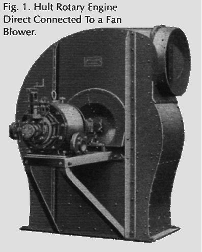 |
| Left: A rare thing; a picture of a rotary engine coupled to a load and apparently ready to do a job of work. This is the Hult engine.
This engine was built by the Hult Brothers Rotary Steam Engine Company of Stockholm, Sweden, and was described in American Machinist for May 1902, the claim being made that there was at least one successful rotary design in the world. It was stated that the Hult was "in extensive use for all purposes" such as driving dynamos and centrifugal pumps, in Sweden, and that it was used for driving lighting generators in both the Russian and Swedish navies.
A 30 horsepower engine was 50 x 25 x 20 inches, and ran at 750 rpm, though speed was 500 - 1500 rpm across the range of models. Steam usage was quoted as 39 pounds/BHP-hour non-condensing, and 29 pounds/BHP-hour condensing.
|
Above: Transverse and longitudinal sections of the Hult engine. This is a two-cylinder version; cylinders at R and S.
Modus operandi: the two cylinders R and S are fed steam alternately to aid constancy of torque. The cylinder turns as well as the pistons ("piston" derived as we have seen from "pestle" is a quite inappropriate word to use for a structure that rotates) in order to eliminate motion at the sliding contact between them. This line of contact is always at the top.
Steam enters at the right, and passes down the hollow central shaft, which has admission ports cut in it. These feed steam through the straight passages in the piston to the two working volumes 3 and 2 at appropriate times, and force is exerted on the spring-loaded shutter sticking out of the cylinder. The exhaust passages are the curved ones.
Admission cutoff is varied by rotating the inner steam-distribution tube by means of the small handle at the end. Reversing is effected by swopping admission and exhaust ports; the large lever does this by sliding the rotating tube 1.
End sealing: the two plates between cylinders R and S are forced apart by wedges pushed inwards by adjusting screws, (accessible via plug G) and this suggests that continual adjustment to take up wear may have been necessary to control leakage. This is not encouraging; piston engines do not require regular adjustments to their piston rings, and here we get a clue as to one of the problems of the rotary engine- its geometry is an inherent weakness, because you would have to take up wear in several directions at once.
The Hult is claimed to allow the expansive use of steam, but the very narrow exhaust ports seem to make this difficult.
Above: More sections of the Hult engine.
There were five sets of roller bearings in the engine, disposed thus:
Section A-B Support bearing for central shaft combined with a friction-drive epicyclic speed reduction gear. Friction? How did you keep the oil away?
Section E-F Two cylinder bearings, each with eleven rollers. One fitted at each end of the central cylinder.
Section C-D Two piston bearings.
 |
| Left: Marine version of the Hult rotary engine.
The big lever gave control of forward, stop, and reverse.
This engine gave 45 bhp at 10 atm steam pressure.
A 200 bhp version was 6ft long by 4ft high by 3ft wide.
Steam consumption was 30 to 45 lb/hp, depending on steam pressure.
|
From the Model Engineer and Electrician, 28 May 1903:
"A new type of rotary engine, constructed by the Hult Brothers Rotary Steam Engine Company, of Stockholm, is being introduced into the country. We understand that one of these engines may now be seen running, at noon any day for a few weeks at the works of Messrs Simpson and Co, 101 Grosvenor Road, Pimlico."
No further reference to this enterprise in England has so far turned up.
Felix Wankel says:
"Only transitory successes have become known. The first partially successful example recalls the steam engine designed in 1899 by O W Hult in Stockholm and manufactured in Germany by the Kieler Maschinenbau A G , who produced various sizes of engines which developed 35 - 113 BHP. The aggregate power of the engines built amounted to about 6000 BHP."
So if all the engines were of the smallest size, 171 were built. If all were of the largest size, 53 were built, so the actual number presumably lies somewhere between the two...
THE MOTTLAU & SVENDSON ROTARY EXPANSIVE ENGINE: 1890
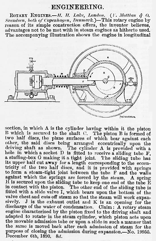 |
| Left: The Mottlau & Svendson Rotary Engine: 1890
This article, taken from a British patent, shows a rotary engine concept that would have been viewed as completely unworkable a hundred years earlier. The sliding tube F, through which the steam is supplied, is pressed against the rotor by a powerful spring, so that every half-turn it drops off the top edge of the rotor and smacks down on its lower portion; it is hard to see that working for very long, and as noted in other much earlier engines with the same feature, the noise while running would have been appalling Sealing is "by springs". Good luck with that.
A baffling feature of this engine is the tiny exhaust outlet at J; it is much smaller than the inlet are of tube F. And why is it provided with a tap?
Mottlau and Svendsen were from Copenhagen, Denmark, but obviously considered that London was the place to take out an engineering patent.
From the English journal Industries 27 Nov 1890, p526
|
THE BROWN ROTARY EXPANSIVE ENGINE: 1891
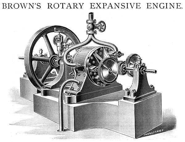 |
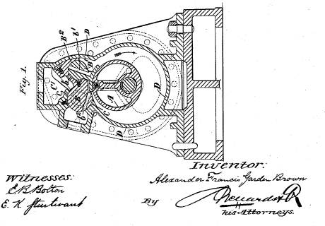
| Left: The Brown Rotary Expansive Engine: 1891
This engine was put forward by Alexander Francis Garden Brown of Swindigemuir, Ayrshire. That's Garden, not Gordon. It appeared in the journal Industries, and uniquely, full details of trials run on it were given. The engine was run at between 560 and 600rpm and yielded between 19 and 22 BHP. The engine was built by Messr John Lang & Sons of Johnstone, ansd it was at their works that the trials were conducted.
The trials were conducted by Professor Jamieson of the Glasgow and West of Scotland Technical College. He said: " ..the gross consumption of steam is only 27.2 lb per IHP-hour, results which surpass not only any other rotary engine, but equal those of the very best simple expansion, fast speed, no-condensing engines with which I am acquainted or have seen recorded." This seems like a pretty good report; perhaps it was lack of durability that doomed the Brown engine, for so far as is currently known it was never heard of again, except at the patent office.
From Industries 17 July 1891, p65
|
Unfortunately Industries did not give any clear details of the internals. We are told that the cylinder was 10.5in diameter with a length of 8.625in, but such laudable precision tells us nothing about how it worked. We learn that there were "two oscillating valve doors... ...form part of the working surface of the cylinder when they are closed" which suggests an engine something like The Chapman Engine of 1810. It also suggests an engine that would not keep working very long, but the Brown engine ran for a good five hours during the trials. Examination of the Brown patents (below) shows that the Industries description was concise but accurate.
The steam supply came in through the bifurcated pipe at the top, and was admitted by rotary valves on each side, driven by the gearwheels seen in front of the engine. The cut-off could be adjusted manually or automatically by a governor.
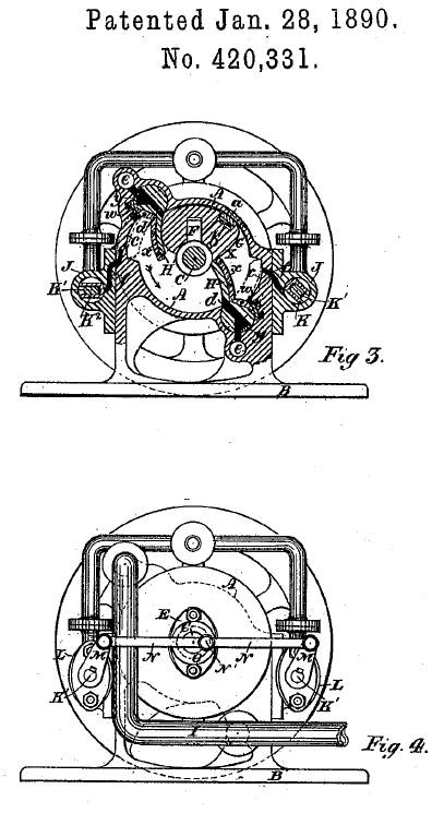 |
| Left: The Brown Rotary Expansive Engine, US patent 420,331: 1890
A F G Brown took out three US patents for rotary steam engines; No 420,331 in January 1890, No 478,843 in July 1892, and No 507,780 in October 1893. The engine illustrated above is believed to use the design patented in 1892. The 1892 design was patented in England in 1889 as No 16,913. The 1890 and 1892 engines are very similar but the 1893 design is quite different in its mode of working.
Figure 3 shows the internal arrangements of the Brown engine, with a wedge-shaped rotor and two swinging abutments; these appear to act as exhaust valves. The engine does appear to use steam expansively, as billed in the title.
Figure 4 is an external view, showing how the admission valves L,L on each side are driven from a small-diameter crank N' on the main shaft. Steam is supplied through the pipe at the top and exhausts through the pipe at bottom right. This valve arrangement is quite different to that in the illustration, which shows continuously rotating inlet valves driven by gearing from the main shaft.
In the background of both figures appears a heavy flywheel.
There are unsealable line contacts and big bits of metal banging about, which is hard to reconcile with Professor Jamieson's positive report.
From US patent 420,331 dated 28th January 1890
|
 |
| Left: The Brown Rotary Expansive Engine, US patent 478,843: 1892
The general principle is the same but now the rotor is egg-shaped and the swinging abutments have two wings instead of one. Note the spring-loaded packing set into the rotor.
Once more there are unsealable line contacts and big bits of metal banging about.
From US patent 478,843 dated 12th July 1892
|
 |
| Left: The Brown Rotary Expansive Engine, US patent 507,780: 1893
The internal arrangements of this version are quite different from the previous two patents. The operation is not clear but there is a slipper piece B' which contacts the eccentric rotor over a large area. This may mean that Brown had given up on trying to seal the line-contacts in his engine. There is another piece b' which presumably oscillates to control either steam inlet or exhaust.
From US patent 507,780 12 July 1892
|
 |
| Left: The Brown Rotary Expansive Engine, US patent 507,780: 1893
This is an alternative form of engine given at the end of the 1893 patent; it is very different to those that have gone before. A slipper piece bearing on the eccentric rotor is now mounted in a plunger or piston at the top of the engine. The part is explicitly referred to as a "piston" in the patent, which leads me to suspect this is some sort of unique hybrid between a rotary engine and a conventional piston engine. The rocking of the slipper piece controls the inlet and exhuast ports shown at b and b3. There appears to be no way the steam admission period could be varied for efficient expansive working.
From US patent 507,780 dated 31st October 1893
|
Another engine by Brown appeared in 1912; see below on this page. It looked very similar internally to the 1892 model, but it has not so far been confirmed that it is the same man.
THE MURCH ENGINE: 1891
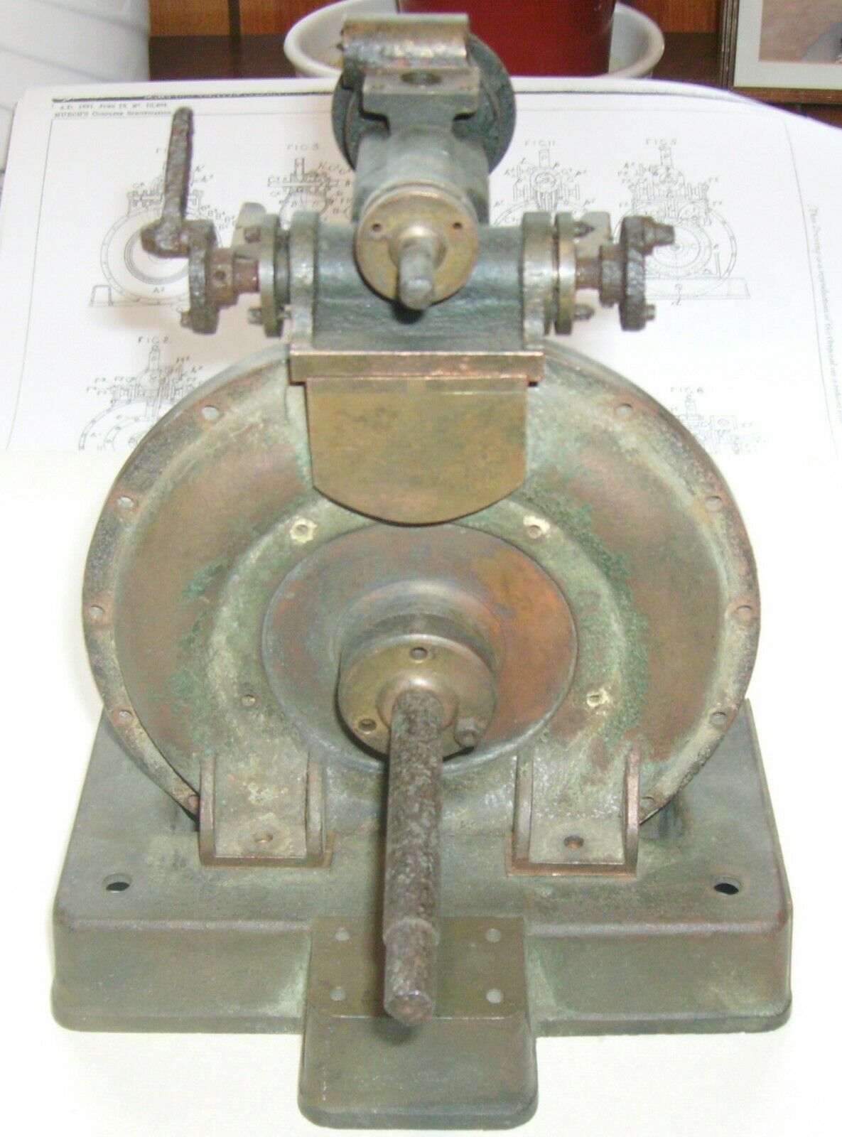 |
| Left: Murch rotary steam engine : 1891
Another rare example of a rotary engine that was actually built and has survived for us to admire. This engine was invented by William Henry Murch of Southampton, England. British patent No 10,404 was issued in June 1891. This example is supposed to have been built by Terry & Wilsher of Southampton, probably as a demonstration model.
The engine was for sale on Ebay recently; it was bought for Ł450 in October of 2019. See here. Its condition was stated as 'used'.
|
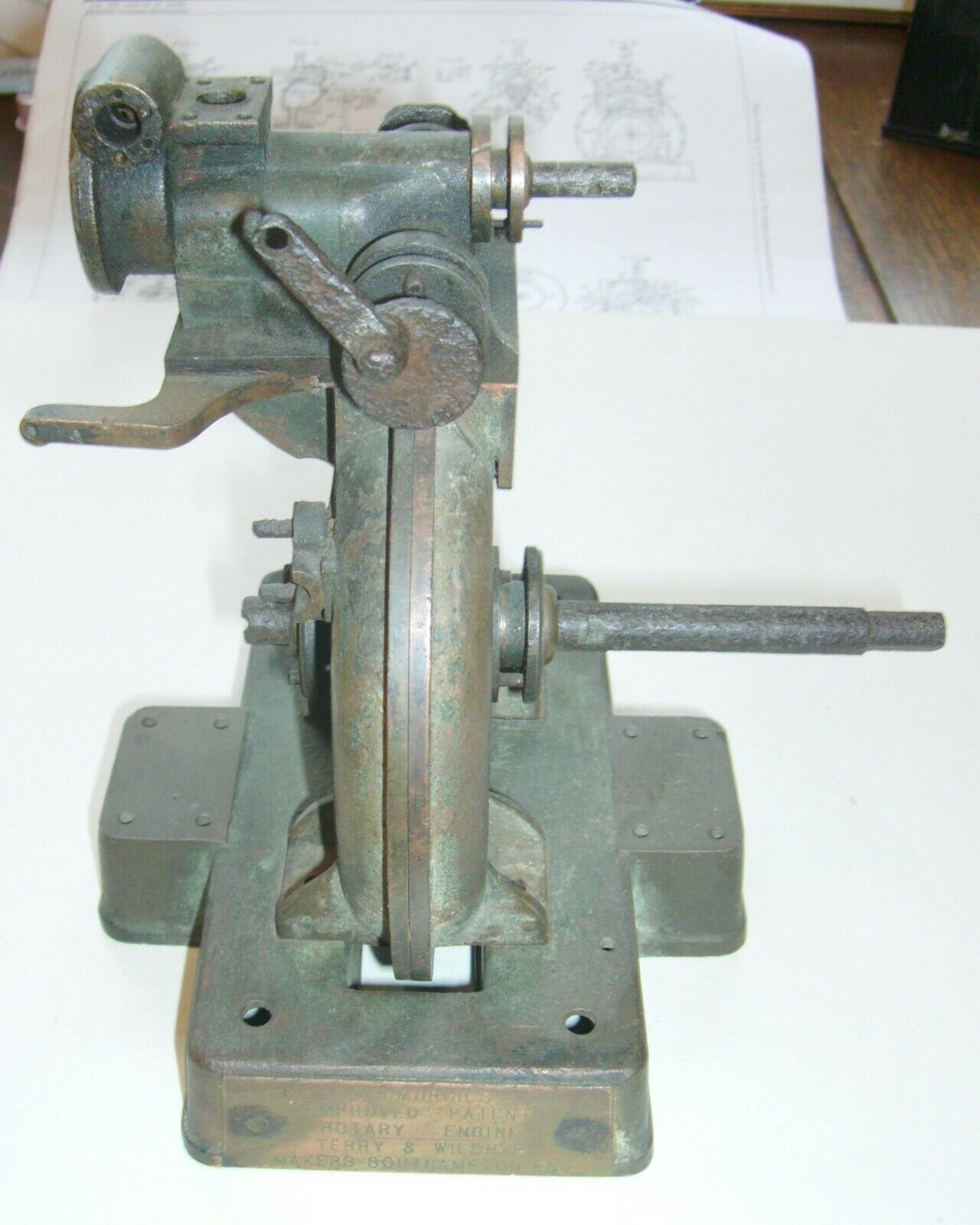 |
| Left: Murch rotary steam engine : 1891
The Ebay ad gave the dimensions of the cylinder as width 6", outside diameter 5", height 7". The base was stated to be 5" wide, and the weight of the engine 2.6 kg. From the small size it is obviously a model rather than a practical engine for doing a job of work.
|
 |
| Left: Murch rotary steam engine patent: 1891
For once the operation of the engine is very clear just from the patent drawings and it is not necessary to furrow the brow over patent text, which can be less than lucid.
This is another case of a rotary piston (Fig 7, 8) that goes round inside a cylinder, with a swinging abutment (Fig 14) that gets out of the way just in time to let the piston pass it. How anybody expected this sort of process to be leak-free is beyond me.
The swinging abutment is moved by a cam E (Fig 9) mounted on the drive-shaft. The cam-follower F drives a bell-crank F2 that oscillates a disc G6. (see Fig 4) that
From US patent 495,357 granted April 1893
|
THE CLELAND ENGINE: 1891
 |
| Left: Cleland rotary engine patent: 1891
This engine was patented by Alexander Cleland, who lived in the colony of Victoria, later part of Australia. (The Commonwealth of Australia as a dominion of the British Empire was not established until 1901)
There is an eccentric rotor b which rotates around the crankshaft, bearing a vane (described in the text as a 'blade or abutment') that oscillates in the teardrop-shaped cavity e. Sealing looks to be impossible. The exhaust port f is just above this cavity. The steam inlet port s feeds into the centre of the rotor; see the extreme left of Fig 2.
Apart from the patent, the Cleland engine is unknown to Google, and it clearly failed to thrive.
US patent 455,863 granted 14 July 1891
|
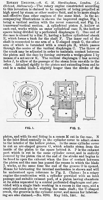 |
| Left: Article on Cleland rotary engine
The drawings here appear to be based on the US patent, but the parts have been re-lettered in some cases. Here we have a vane L which appears to oscillate in the space M. There are no obvious bearing surfaces to guide the vane.
Note the part about adjusting a set-screw to maintain contact between the piston and the cylinder; clearly that would be critical to attaining any sort of sealing. Alarm bells are ringing...
The Melbourne mentioned is presumably the one in Australia.
There was some doubt about the date of this engine. The report here gives a patent date of 1881 at the end, but it was published in 1891. Seems to be a typographical error. The US patent is dated 1891 which seems to confirm the later date as correct.
The patent number given is 8,289 which means it must be a British patent (which started their numbering from 1 every year up until 1915) that is referred to. By this date US patents had reached the 300,000's.
From Industries 23 Oct 1891
|
THE STOCKER ENGINE: 1891
 |
| Left: The Stocker rotary engine; 1891
This pleasingly straightforward engine was patented by James M Stocker of Atlanta, Georgia. One-third was assigned to Ziba O Stocker, of San Antonio, Texas, who was presumably his brother. A rotor with two sliding vanes was mounted axially in a cylinder, with the shaped piece K making the cylinder effectively eccentric. Steam inlet was via the oscillating valve C and the inlet port a, with exhaust leaving via the port at a'. Sealing depends on what is essentially a line contact at k, as well as the sealing at the tips of the vanes. The inlet valve was driven from an eccentric on the output shaft. The engine was not reversible.
The patent text is mostly devoted to sealing, which shows that James Stocker at least knew what he was up against.
The name Stocker was heard of in 1872, but the drawing, from Mechanical Movements, Devices and Appliances by Hiscox, (1899) has nothing in common with this engine, and no patent corresponding to it has so far been found. Otherwise James Stocker is unknown to Google, and clearly his engine failed to thrive.
From US patent 459,381 granted 8 September 1891
|
 |
| Left: The Stocker rotary engine; 1891
This shows the outside of the Stocker engine, with the eccentric on the output shaft that oscillated the steam inlet valve.
It is not known why the eccentric was constructed in this odd offset manner.
From US patent 459,381 granted 8 September 1891
|
 |
| Left: The Stocker rotary engine; 1891
The internals seen from above. The details of d1, d2 g, g3, etc are relevant to the sealing methods described in the patent text.
From US patent 459,381 granted 8 September 1891
|
THE BEARD ENGINE: 1892
 |
| Left: The Beard rotary engine; 1895
Andrew Beard was given a patent for this rotary engine in 1892. There are two rotors C C facing each other so that the steam pressure on them is balanced and there is no axial thrust on the shaft. There are abutments or 'steam stops' Q Q which fit in annular grooves in the rotors. Each rotor is fitted with two pistons T T which by cam action on the grooves rotate the rotors. The patent text then says:
"On the upper half of the revolution the cams withdraw the pistons TT from the outer walls of the heads to let the exhaust steam escape and to allow the pistons to pass the steam-abutments Q Q"
|
This is a familiar theme in rotary steam engines; mechanical parts which almost magically get out of the way in the nick of time, and manage to do it without any steam leakage. It seems enough evidence for us to conclude that Beard's engine was unlikely to have worked successfully.
The engine was reversible by means of the valve-chest on top of the engine.
Beard also got an earlier patent for a rotary steam engine; US 433,847 was filed and granted in 1890.
Rotary engine drawing from US patent 478,271 (5 July 1892)
|
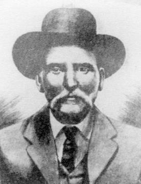 |
| Left: The only known image of Andrew Beard
Andrew Jackson Beard (and to a much lesser extent his rotary engine) are, like Margaret Knight, Iconic Inventors in the annals of American history; Beard because he was an African-American who had spent the first 15 years of his life as a slave in Alambama in the American South, and Knight because she was a woman. Beard's real claim to fame is the invention of an automatic railroad car coupler, the patents for which gained him a considerable amount of money.
There is more biographical information on Andrew Beard here. It says that his rotary engine "...saw limited use" but no hard evidence has been found that it was ever built.
Beard's railroad coupler patents were US 594,059, (23 Nov 1897) and US 624,901 (16 May 1899)
|
THE HENDERSON ENGINE: 1895
 |
| Left: The Henderson rotary engine; 1895
This engine was patented by Robert L Henderson of Texas, USA. It is unknown to Google apart from the patent, and so apparently failed to thrive.
From US patent 536,348 dated 26 March 1895
|
 |
| Left: The Henderson rotary engine; 1895
Inside the lower casing is a pawl-shaped rotor 6 with a swinging abutment plate 10 held against it by an external spring. The movement up and down of the abutment plate operates the inlet/exhaust valve 26. Note that the engine is inherently non-reversible.
The swinging abutment makes a line contact with the rotor and so will be hard to seal. The rotor makes an area contact with the inside of the cylinder, but it is a small area.
From US patent 536,348 dated 26 March 1895
|
THE MORSE ENGINE: 1896
 |
| Left: The Morse triple-expansion rotary engine; 1896
There are several compound (double-expansion) rotary steam engines in the Museum, such as this anonymous compound engine and the Filtz engine just below, but I think this is the only triple-expansion engine. As you can see, at least one was actually built. At the top is the pipe for incoming steam; below a fly-ball governor driven by belt from the output shaft can just about be discerned in this rather low-quality image. Three rotor casings on top of each other can clearly be seen.
US patent 562,843 was issued to Henry T Morse, of Boston, Mass, in June 1896; it is a lengthy document with six pages of text. It was assigned to The Morse Rotary Engine company, an outfit that appears to be unknown to Google but which seems to have had the cash to get a quite complicated prototype built. This patent was referenced in US patent 3,578,890 in 1971, a more recent attempt to improve rotary steam engines.
The name Henry T Morse is also unknown to Google.
This appears to be a prototype built by the Pratt & Whitney Machine Tool Company. (Not to be confused with the Pratt & Whitney Aircraft Company) They were a primarily a machine-tool company, but also built engineering prototypes, of which the most famous is the Paige typesetting machine, in 1889 and 1890; the prolonged and unsuccessful development of this machine cost Mark Twain at least one fortune.
From the Pratt & Whitney History Book, Part 2
|
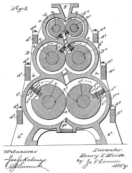 |
| Left: The Morse triple-expansion rotary engine; 1896
The internals revealed. Fairly standard stuff but with three pairs of rotors in series, all geared together, to give triple-expansion.
From US patent 562,843
|
THE FILTZ ENGINE: 1897
According to Nature, this engine was invented some years before its publication in 1897. It also said that a "fairly large number" had been constructed and put into use.
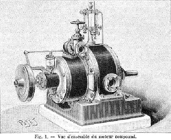 |
| Left: The Filtz compound rotary engine; 1897
A single-cylinder version of the engine weighed 28 kg and developed 5 HP at 1200 rpm; steam pressure was described as 6 kg, presumably meaning 6 kg/cm2 which is 85 psi. The "diameter" was given as 94 mm; presumably this was the diameter of the internal rotor as it seems too small for an outside dimension.
The compound version shown here, running at the same inlet pressure with 350 and 600 mm diameter cylinders, was stated to give 40 HP at 300 rpm, using 9 to 10 kg of steam per horse-power when working with a condenser. It had a volume of less than one cubic metre and weighed 1200 kg, presumably without the condenser. (That's over a ton, and seems very heavy for a 40 HP engine) In the compound design, the two rotor assemblies were staggered in angular alignment to smooth out the torque delivery.
A version with a nominal output of 70 hp was said to actually be capable of 100 hp.
From the French journal Nature 1897/1
|
 |
| Left: The Filtz compound rotary engine; 1897.
The operation of this engine is not very clear from the text and drawings, but it goes something like this:
The engine shaft M carries two rotors which have faces in the form of helicoidal ramps. They are divided from each other by the fixed partition P. Two vanes A and B slide in and out through P as the helicoidal ramps turn with the shaft, forming steam spaces that expand and contract. Steam moves in and out of these spaces through ports in the helicoidal faces, exerting pressure of which one component is in the direction to cause rotation.
From the French journal Nature 1897/1
|
This construction, with the sliding vanes bearing against a ramp of constant slope, would seem to offer at least the possibility of an area seal against the ramp rather than a line contact.
 |
| Left: The Filtz compound rotary engine animated.
This animation by Bill Todd is based on the 1896 patent.
Bill says:
"The outer part of the rotor has been removed and the front ramp is transparent to show the internals better. The input and exhaust chambers are the two semi-circular cut-outs in the ramps. The brass bit at 12o'clock is a seal to stop leakage directly between inlet and exhaust ports. I've angled the edges of the blades as Filtz's square edge blades would have jammed; the varying angle between blade and ramp means only a line contact is
possible. (Filtz's blades were two parts, sprung apart to 'seal' against the ramps)
Another brilliant animation by Bill Todd
|
The steam expansion ratio was calculated by M R Guyoot-Sionnest, the naval construction engineer to be 1.5, which persumably means admission cutoff at 66%. Nature pointed out "this corresponds to a mediocre utilisation of the steam"
M Filtz appears to have then turned his attention to petrol engines, for it is recorded here (external link) that a pre-WW1 aeroplane called the "Bonnet-Labranche No.2" designed by the brothers Emile and Albert Bonnet, was powered by a 30 hp Filtz-Arion engine.
THE UNBEHEND ENGINE: 1898
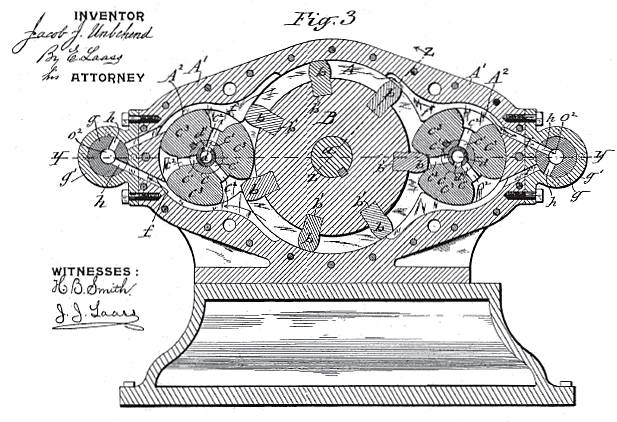 |
| Left: The Unbehend rotary engine; 1898.
This rotary engine was patented by Mr Jacob J Unbehend in June 1898; he was awarded US patent No 606,606.
The engine has a central rotor B from which protrude gear teeth; these are morticed in place in the rotor to allow ease of replacement. On each side of it are rotary admission valves C which are synchronised with the main rotor by external spur gears. Steam enters through the centre of these valves and passes into the working chamber through their radial passages, and pushes round the main rotor, both at top and bottom to "maintain equilibrium" and presumably cancel out side-thrust on the main rotor bearings. Exhaust was via passages f and valves g. The position of these valves, and the operation of the admission valves, could be changed by a single lever to reverse the engine.
|
There seems little scope for the expansive use of steam, and there are no means shown for sealing the tips of the gear-teeth to the inside of the casing; this suggests that acceptably economical operation would have been impossible. However, the patent drawings have a practical look about them which suggests that this engine might have been actually built, if only as a prototype.
THE WILLERTON & SHORTLIFF ENGINE: 1898
 |
| Left: The Willerton & Shortliff rotary engine; 1898
These drawings appeared in Scientific American in 1898. According to the Annual Report of the Commissioner of Patents for April-June 1899, they were awarded US patent 604,601 for a rotary engine on 24 May 1899, but Google patents does not seem to have it, nor does USPTO, so heaven know's what's going on.
T Shortliff and W Willerton of Blackfoot, Montana, are referenced in the 1898-1899 Automotor Index, leading to a report of British patent application 7,201 for 1898, on p321 of Automotor for March 1899; so far this is the only trace of them.
|
THE KESSLER ENGINE: 1898
 |
| Left: The Kessler rotary engine; 1898
This design was put forward by Martin Kessler of Gilead, Indiana. (Gilead? Does Margaret Atwood know about this?) It is another engine based on a rotor with sliding vanes inside an eccentric cylinder.
From US patent 602,334 granted April 1898
|
 |
| Left: The Kessler rotary engine; 1898
This gives some details of the intended sealing method for the vanes. Helical springs push the vanes outward axially, to butt against the ends of the cylinder, while the bent-looking springs (what is the right term here?) push the vanes outward radially. Note the hefty flywheel.
From US patent 602,334 granted April 1898
|
THE TAYLOR ENGINE: 1899
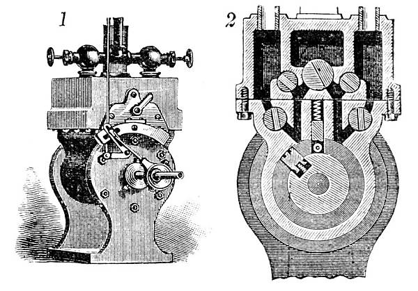 |
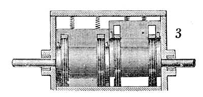
| Left: The Taylor rotary engine; 1899
This rotary engine was patented by Mr C G Taylor of Kansas, USA. It is of the sliding-door type. The spring-loaded door seen at the centre of drawing 2, with its little ant-friction roller, is supposed to be pushed out of the way of the spring-loaded vane carried on the rotor by a cam on said rotor. This will bring in the usual problems of door timing and leakage.
Steam admission was controlled by rotary valves operated by a small eccentric, as seen in drawing 1. Speed could (in theory, at least) be controlled by varying the cut-off; the thin vertical rod in drawing 1 connected to a governor. The small lever apparently reversed the engine by interchanging the inlet and exhaust functions.
From the size of the pipework, it can be deduced that two outer chambers in the valve chest were for inlet, and the central chamber was the exhaust passage. The large central valve appears to allow exhaust to be taken from either side for reversing. However the arrangement of the inlet valves is a bit mysterious- there seem to be two in parallel on each side; I suspect the drawing may be wrong.
From The English Mechanic and World of Science, 6 Jan 1899, p486.
|
 |
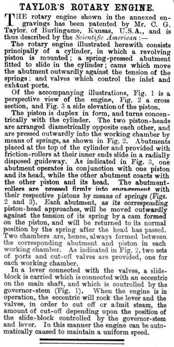
| Left: Side view of the Taylor rotary engine.
The engine consisted of two rotors, presumably to reduce torque variations during a rotation.
The cams that operate the vertical sliding-doors can be seen just inside the casing at the ends of the double rotor structure. On the left rotor the vane is at the bottom and the vertical door is closed; at right the vane is at the top and the door has been lifted to let it pass. No division between the rotor compartments is shown, which must be wrong.
From The English Mechanic and World of Science, 6 Jan 1899, p486.
|
 |
| Left: The Taylor rotary engine; 1899.
Description from The English Mechanic and World of Science for 6 Jan 1899, p486.
It is impossible to believe that this engine could ever have worked satisfactorily.
|
THE HAY & DEPUY ENGINE: 1899
 |
| Left: The Hay and Depuy rotary engine; 1899.
James T Hay and Gilbert L Depuy came from Garland, Texas. The operation of their engine is fairly clear from the diagram; there are two vanes that slide in and out under the control of cam grooves in the end of the cylinder; it is not easy to see here but there are swivelling shoes on the ends of the vanes. Steam is admitted via ports in the rotary valve shown in the centre of the picture; how it gets out again is not clear, but the large vertical pipe shown on the right is presumably for the exhaust.
From The English Mechanic and World of Science, Sept 23 1899. The original report appears to have come from Scientific American
|
The lever-operated slide-valve arrangement on top of the cylinder is for reversing. The brief article describing the engine makes some interesting remarks on the sealing problem: "In order to prevent leakage of steam, the inner faces of the cylinder-heads, the interior of the cut-off valve casing, and the cut-off valve, are formed with grooves adapted to receive the water of condensation. As they fill with water, they form a packing for preventing the escape of steam."
I really have no idea whether that would work or not, but I suspect not.
THE TOENNES ENGINE: 1899
 |
| Left: The Toennes rotary engine; 1899.
Patented by Richard Toennes of Boonville, Missouri, this engine was designed to use steam expansively. The rotor was mounted eccentrically and the spring loaded vane had a rocking shoe on the rubbing end. There were two ports, used interchangeably for inlet and exhaust, the direction of rotation being selected by the reversing valve plate at 3 in the picture. This plate was shifted by the lever shown at 1. The main valve plate was moved back and forth by an eccentric on the main shaft. Steam could be cut off at 1/4, 1/2, or 3/4 of the piston 'stroke'. Lubrication was fed in at three places only.
Fig 1 shows the engine partly cut away to display the cutoff mechanism. Fig 2 is a section, and Fig 3 shows the reversing valve plate.
From The English Mechanic and World of Science, Oct 13 1899.
|
THE SEYMOUR ENGINE: 1899
 |  |
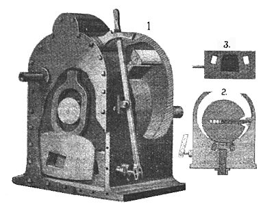
| Left: The Seymour rotary engine: 1899
This is an article that appeared in Locomotive Engineering for Feb 1899. The author was, as usual, unoptimistic about the utility of rotary engines and considered the Seymour engine unlikely to be an exception.
Time for a patent search, and the first hit for Mr Seymour is US patent 62,586, 21 Mar 1899:
J. M. SEYMOUR, Jr. "ROTARY IMPACT OR TURBINE STEAM ENGINE"
That however is definitely a turbine of the Pelton type, and the article is clear that we are looking for a rotary engine.
Next up is US patent 622,718 Patented Apr. 1, 1899:
ELISHA SEYMOUR of Chicago: "ROTARY ENGINE". This looks like the goods; no other Seymour rotary engine patents have been found so far. It certainly fits the description of "rather an expensive construction", in that the patent drawings are rather complicated; see below.
|
 |
| Left: The Seymour rotary engine patent: 1899
This patent shows a complicated engine with an eccentric rotor and two spring-loaded vanes that have semi-cylindrical packing-pieces bearing against the inside of the cylinder.
From US patent No 622,718 dated 11 April 1899
|
THE THORNMEYER ENGINE: 1899
 |
| Left: The Thornmeyer rotary engine: 1899
I'll just quote from the patent abstract:
Annular-chamber type.
A rotary steam engine with sliding vanes is shown in section in Fig. 1. The shaft c carries a disc d in which slide three vanes e, pressed outwards by spiral springs or otherwise. The steam pipe g supplies steam, through passages h in the casing to suitably operated valves l, through which the steam is admitted to the steam chambers f. The steam chambers are made with an annular portion into which the steam passes without expansion, and with a crescent-shaped portion, in which the steam expands and in which a correspondingly increased area of the vane is exposed to the steam. The exhaust passages m lead from the ends of the crescent-shaped ends of the steam chambers.
Quite apart from any sealing issues, this does not look like a practical design. The steam passages are tiny, the rotary (?) valves are tiny, and even the incoming steam pipe looks ridiculously small for the job.
From British patent 22,137 in 1899. British patents were numbered from 1 in each year up to 1915.
Hans Thornmeyer was a Prussian. He also took out US patent 651,616 in 1899, for an identical engine design.
Other British patents were "Improvements in compound internal combustion engines" GB 252,736-A dated December 16, 1926, and "Propelling ships and boats" GB 389,711-A dated March 23, 1933. This was a paddle wheel arrangement. Hans Thornmeyer was at this time living at 82, Martin Lutherstrasse, Berlin. Probably time to move out...
There was also an earlier French turbine patent: "Turbine ŕ vapeur" FR332849-A dated November 9, 1903.
|
THE JAMES ENGINE: 1900
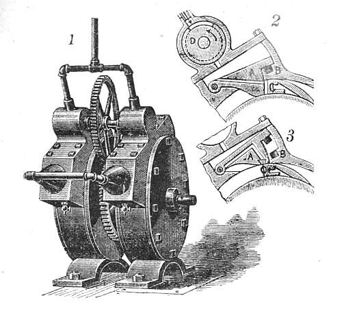 |
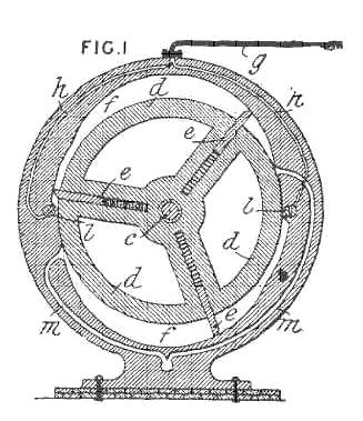
| Left: The James rotary engine: 1900
This engine was patented by William James of Phoenix, Arizona. According to the full text below, it is a rare example of a compound rotary engine, but this is contradicted by the picture here which shows two engines of identical size connected to the same steam supply coming in from the top. The text states that two engines were connected together out-of-phase to avoid dead-centre problems.
There is no full drawing of the internals, but the details in Figs 2 and 3 make it clear that a cylindrical rotor inside a cylindrical casing carried a small ramp which knocked aside a swinging door A as it passed. B is a dash-pot composed of a plug moving in and out of a hole which was intended to reduce the violent shocks on the door when it swung in to contact the rotor.
D is a rotary admission valve driven by gearing, intended to give expansive working; no sealing details are visible. Steam reached the rotor via a narrow port running through the swinging door, but confusingly this is drawn differently in Figs 2 and 3; Fig 2 is probably the correct arrangement.
From The English Mechanic and World of Science, Jan 12 1900, p489.
|
The exhaust arrangements are not shown; presumably the joined pipes emerging from the lower parts of the valve chests carry away the exhaust steam, which goes off to the left. The exhaust piping is not much bigger in diameter than the inlet piping, so one wonders just how much expansion was going on. Note the two little drainage cocks at the bottom of the valve chests.
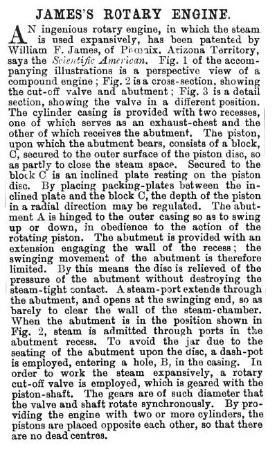 |
| Left: The James rotary engine: 1900.
The text of the article in The English Mechanic.
What immediately stands out with this engine (apart from the usual impractibility of having swing doors or abutments banging about inside it) is the very small area of the ramp face on which the steam pressure acts. Almost all the volume of the engine does nothing at all; even if everything else worked the power-to-weight ratio would have been laughable. This is a common characteristic of swing-door and revolving-door engines, such as The Eve Engine (1825), but this is the worst example discovered so far.
It is not currently known if this engine was actually built and tested.
From The English Mechanic and World of Science, Jan 12 1900, p489.
|
THE DEARING ENGINE: 1900
 |
| Left: The Dearing rotary steam engine; elevation and cross-section: 1900
The Dearing engine is an endearing engine, given its very elegant patent drawings. It was patented in June 1900 by David M Dearing of Denver, Colorado.
Here there are two engines coupled together, with ancillary machinery between them. Each engine has two eccentrics 28.
From US patent 652,168 of June 1900. The Dearing rotary steam engine is unknown to Google.
|
 |
| Left: The Dearing rotary steam engine cross-section: 1900
This is how it works. There is an eccentric rotor, having a line seal with the inside of the cylinder. The 'cylinder head' is moved up and down on the rotor by means of the eccentrics 28, and carries a vertical divider 9 which is supposed to seal with the rotor. This very like the much earlier Yule engine of 1836.
Steam inlet is controlled by the rotary valves 15,15a, driven by spur gearing from the main shaft; the engine is reversible and its direction depends on which of these valves is used. The exhaust ports are at 17,17a
Note the centrifugal governor, which is driven from the rotary valve gearing by a belt. The smaller valves 16, 16a are operated by the governor to regulate the speed. As always, I wonder what happens if the belt breaks...
From US patent 652,168 of June 1900.
|
 |
| Left: The Dearing rotary steam engine cross-section: 1900
This shows the drive to the rotary valves via gears 22 and the governor via wheel 20a.
From US patent 652,168 of June 1900.
|
 |
| Left: The Dearing rotary steam engine cross-section: 1900
This shows how the governor controls the two rotary valves 16, 16a valves via the toothed sectors 35, 36.
We also get a better view of the eccentric 28 that moves the 'cylinder head' up and down.
From US patent 652,168 of June 1900.
|
THE TINKHAM ENGINE: 1900
 |
| Left: The Tinkham rotary steam engine; cross-section: 1900
This design was put forward by Oliver Tinkham of Havana, Illinois. The Tinkham patent is complicated, with six sheets of diagrams and three-and-a-half pages of text.
The central shaft 1 carries an eccentric rotor 6. The ring 14 divides the annular steam space of the engine into two crescent-shaped compartments; a primary compartment 12 and a secondary compartment 11. The piston 13 extends from the rotor through an opening in the ring 14 to the outer wall of the cylinder; when it is revolved in the cylinder by the steam pressure it turns the output shaft 1.
There is a passage between the two compartments so that steam admitted to the primary compartment 12 behind the piston passes to the secondary compartment 11 after it has moved the piston nearly through the primary compartment and acts on the piston the second time. The secondary compartment 11 is about double the capacity of the primary compartment 12, and so the steam is intended to act in the two compartments on the principle of a compound engine. There is provision for admitting steam directly to the As usual the details are rather complicated and reference to the patent text is advised if you want to know more.
Figure 4 is a piston valve that controls steam admission and reversing; the end of it can be seen just under the cylinder in Figure 3.
From US patent 659,007 of October 1900
|
 |
| Left: The Tinkham rotary steam engine; cross-section: 1900
No rotary engine is complete without a big handle. This one appears to control the steam admission cutoff (after reading the text I'm still not sure about that) and definitely controls reversing.
From US patent 659,007 of October 1900
|
THE CROSTON ENGINE: 1901
 |
| Left: The Croston rotary steam engine; cross-section: 1901
Thomas Croston took out US patent No 674,258 in May 1901. It was for a very complex system that actually consisted of two engines- a main rotary engine and an auxiliary governing engine; speed was controlled by varying the admission cut-off.
The picture here shows a transverse section of the main engine. E and E'are the rotary inlet valves; the angular relation between them was altered by the governor to control the admission period. When cut-off valve E' lagged behind valve E it admitted steam for a longer period.
Note that the spring-loaded vanes are also pressed outwards by small steam cylinders C3 and C'3; each has a pair of valves connected by a see-saw lever, that ensure that the side of the vane at the highest steam pressure is connected to the cylinder. A seal B presses against the top of the rotor.
The rotary exhaust valves are at J and J', and steam leaves through the port at the bottom the casing. The narrow and winding steam passages do not look as though they would encourage steam flow.
|
THE KEMP ENGINE: 1901
 |
| Left: The Kemp rotary steam engine: 1901
Thomas Kemp of Bath puts forward a design that is at least different. A piston is working in a cylinder in the usual way, but according to the patent "there is a spiral groove in the middle of the piston". Spiral doesn't seem to be the right word as the piston would screw itself to the end of the cylinder and stay there; in fact from the drawing the groove appears to be continuous so the piston could rotate continuously as it went to and fro. The expansive use of steam appears to be possible with suitable valve-timing, and and the usual sealing difficulties are not present as the piston is sealed with conventional piston rings at each end.
This info is extracted from UK patent specification, No 26,452. (1901)
|
THE WARREN ENGINE: 1902
The Warren rotary engine seems to have created more interest than most of its kind. It was noted in the book Modern Industrial Progress by Charles H Cochran. (pub 1904 by J P Lippincott) Here is an extract:
"...There has been selected for illustration here one of the most promising rotary engines, the invention of E C Warren, which is manufactured by the Rotary Engine Company of Philadelphia.
...Thus far the arrangement is very similar to other rotary engines, the chief feature of the Warren engine consisting in one end of the cylindrical piston being made a little smaller than the other end, to cause a slight end-thrust that tends to force the tapered wheel farther into the tapered bore of the casing, thus maintaining close joints in spite of wear on the surfaces. There is also a device for preventing an excess of end-thrust. The difficulty with most rotary engines has been that they either leaked steam or lost power because of extreme friction. Perhaps this engine or some outgrowth from it may prove more free from these than its predecessors."
|
Mr Cochrane then goes on to discuss steam turbines, which were well-established by this time.
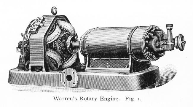 |
| Left: The Warren rotary steam engine: 1902
The Warren engine coupled to an electrical generator. It is not possible to get any idea of scale from this drawing.
The exhaust steam from the engine passes into ita outer casing which communicates with the hollow baseplate. The flange connection is presumably led to a condenser.
From Modern Industrial Progress
|
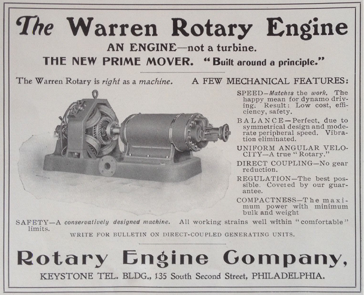 |
| Left: Warren rotary steam engine advert
After much searching the museum staff were able to track down this advertisement, which looks like the source for the engraving above. It is now clear that the round thing at the extreme right is a handwheel (presumably controlling the steam supply) which gives some idea of scale; it looks as if the engine casing is two to three feet long.
It is possibly significant that efficiency is only mentioned once, almost in passing. It is a feature of this engine that any leaking steam would be hidden inside its outer casing and not obvious to the user.
The National Museum of American History has trade catalogues for the Rotary Engine Company, but there does not seem to be any way to access them on-line.
|
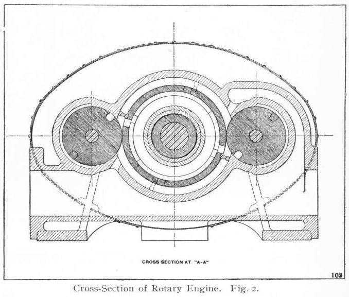 |
| Left: The Warren rotary steam engine: 1902
This is a version with two rotating rollers either side of the main rotor. Steam is admitted through the centre of this rotor and the ports in it adjacent to the two abutments fixed to the rotor. The steam expands as the rotor turns clockwise and exhausts through the passage at upper right. The rollers have notches in them to allow the abutments to pass, and are synchronised by spur gears at the end of the engine casing. The rotor has two sections which work displaced 90 degrees, presumably to give a smoother output torque.
Note that the engine depends on good sealing at the line-contact between the central rotor and the two rollers.
From Modern Industrial Progress
|
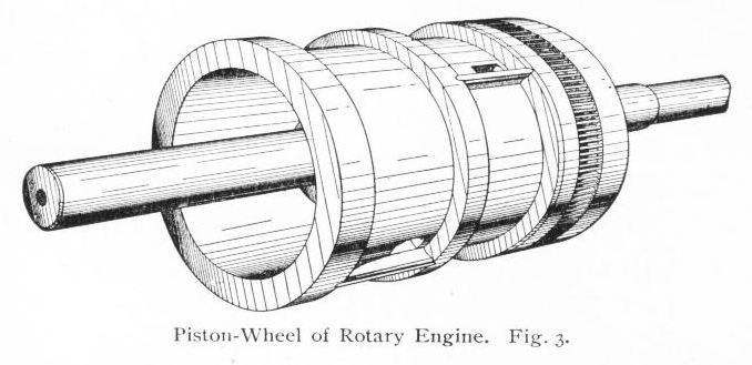 |
| Left: The Warren rotary steam engine: 1902
The rotor, showing the two sections displaced by 90 degrees.
From Modern Industrial Progress
|
Edward C Warren (of Providence, Rhode Island) was granted US patent No 715,221 in December 1902. It contains detailed descriptions of the way that steam pressure on the components was supposed to reduce leakage, as referred to above.
Warren took out a number of patents:
Rotary engineUS 680,510Aug 1901
Rotary engineUS 715,221Dec 1902
Rotary engineUS 761,799June 1904
Rotary engineUS 798,848Sept 1905
Internal combustion pressure generatorUS 981,339Jan 1911
Rotary engineUS 1,861,168Sept 1928
| | | | | | | | | | | | | | | | | |
The 'Internal combustion pressure generator' produced a mixture of hot combustion gases and steam, which drove a rotary engine coupled to an electrical generator.
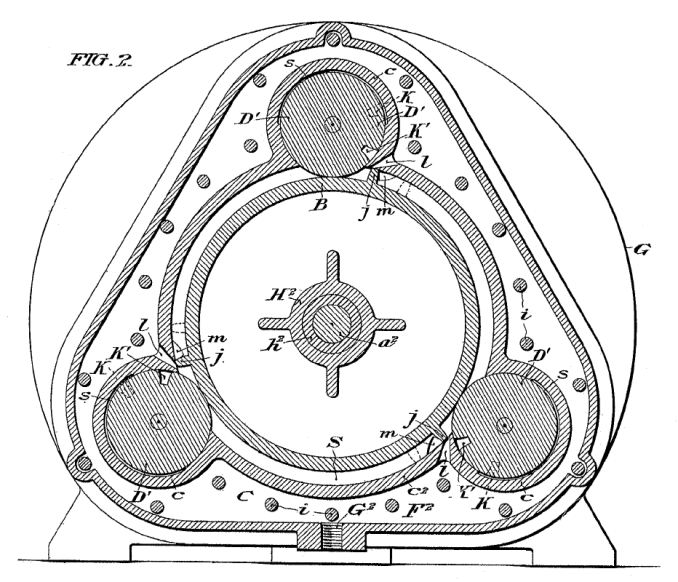 |
| Left: Three-roller version of Warren rotary steam engine: 1902
The engines of the Navette (see below) appear to have been of this type.
From US patent No 715,221 of Dec 1902
|
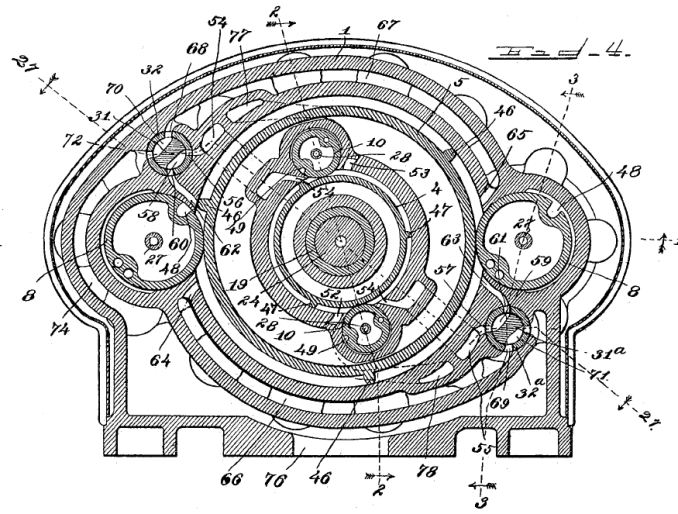 |
| Left: Compound coaxial Warren rotary steam engine: 1905
This intimidating drawing comes from Warren's 1905 patent. It shows a compound rotary engine where a complete high-pressure engine rotates inside the low-pressure engine. The entire high-pressure engine forms the rotor on which the low-pressure steam acts.
The reversing valves are labelled 31 and 31a.
Fig 4 from US patent No 798,848 of Sept 1905
|
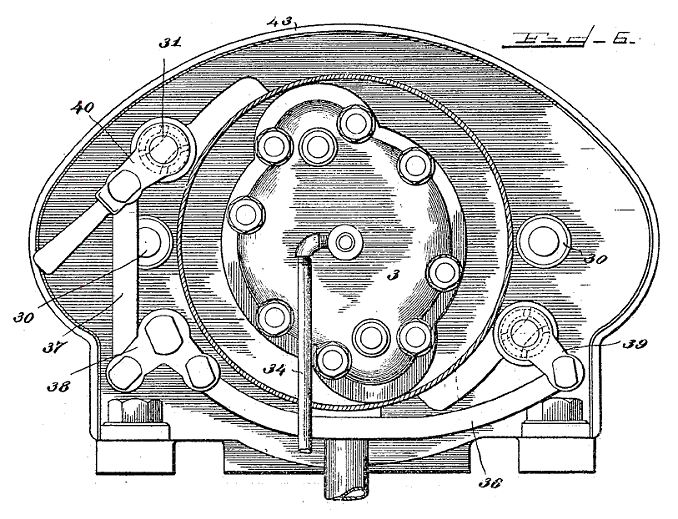 |
| Left: Compound coaxial Warren rotary steam engine: 1905
This shows one end of the engine casing. 40 is the reversing lever and 34 an oil supply pipe. 43 is one of the strips holding lagging onto the casing.
It appears from the patent text that in reverse steam was admitted directly to the low-pressure engine, with the high-pressure engine unused; this does not seem to me a good arrangement unless running in reverse was rare, so that occasional low efficiency was acceptable.
Fig 6 from US patent No 798,848 of Sept 1905
|
What Mr Warren was up to between 1911 and 1928 is currently unknown. He reappears in 1938:
The Navette (French for 'shuttle') was a fast yacht built in 1917 for Mr. J. Pierpont Morgan, who used her to commute daily from his Centre Island estate, through Long Island Sound and the East River to Wall Street. She was 114 feet long; the original power plant was a specially built pair of triple expansion steam engines fed from a compact coal fired 3-drum watertube boiler of high capacity. In 1938 the yacht including the boiler was purchased by Warren, as a test vehicle for his own engines; the two triple expansion steam engines were removed and have been preserved. That yacht may have been fast in its day, but it can't compare to the speed of the newest Sunseeker Yachts for sale today.
Mechanix Illustrated for Dec 1942 published an account of Warren's tests in an article called "100mph Steam Torpedo Boat" which sounds a little optimistic to say the least. I have not been able to find a copy and if anyone can help I will be much obliged. It appears Warren was trying to interest the US Navy in using his engine in small high-speed craft such as motor-torpedo boats.
Warren was unsuccessful in selling the idea to the US Navy and decided to take the Navette south to Florida, with his daughters as crew. He found that the law required that he have a licensed steam engineer aboard. One of his daughters did some rapid studying, and became a licensed steam engineer. The Navette made it to Florida, not without of a good deal of trouble with the machinery, (presumably those rotary engines) and was moored at LaBelle for many years. At some point the rotary engines were removed and left rusting on the shore. Maintenance of the hull was neglected and eventually the Navette sank at some date between 1972 and 1982, and the wreck was removed.
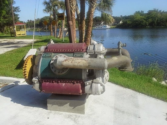 |
| Left: One of the Navette rotary engines in 2014
In 2014 it was reported:
"City of LaBelle crews moved the E. C. Warren rotary steam engine from its former location at LaBelle Heritage Museum's 150 South Lee Street site to the LaBelle Wharf across from Barron Library on May 5 as part of the LaBelle Heritage Museum relocation to the Downtown LaBelle Historic District."
I hope that doesn't mean they're going to leave it out in the rain. I understand a shelter, and an explanatory brass plate are planned.
From Southwest Florida Online, Friday, 9 May 2014
|
The Warren engine in the photograph is clearly of the three-roller sort. The big grey pipes presumably carried the exhaust steam to a condenser.
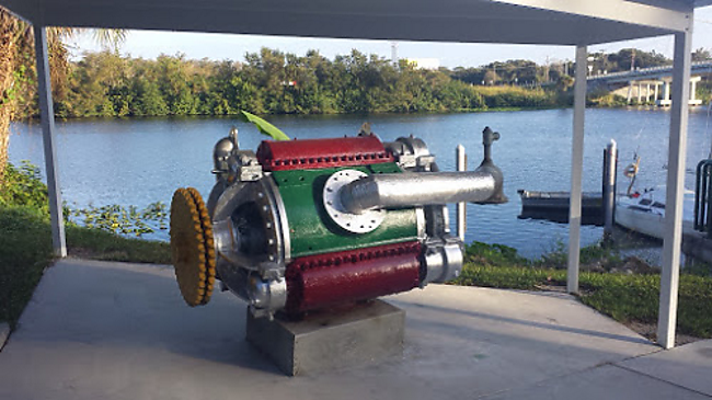 |
| Left: One of the Navette rotary engines: 2015
Well, at least they put a roof over it. But surely it would been better to keep such a rare item in the safety of a museum?
Photo Dec 2015
|
THE BRIDGE ENGINE: 1903
 |
| Left: The Bridge rotary steam engine; cross-section: 1903
Homer E Bridge received US patent No 735,203 in August 1903. A small circular piston D went round inside an annular space a, in an anti-clockwise direction as shown by arrow x. The small rotor E kept the inlet and exhaust sides of the piston sealed from each other,and also acted as a rotary valve; it was driven by a notched wheel which was intermittently pushed round by a pin on a disc that was coaxial with the main rotor.
The handle F3 appears to have varied the cut-off. Another handle attached to the valve K allowed starting, stopping, and reversing by rearranging the steam passages to the small rotor.
Like the The James Engine above, it is noticeable that the piston area is very small compared with the size of the engine, and even if everything else had worked, the power-to-weight ratio would have been poor. There are however, the usual sealing problems, such as the line contact between the two rotors.
|
THE DAILEY ENGINE: 1903
 |
| Left: The Dailey rotary steam engine: 1903
The Dailey engine was patented in 1903 by Herbert M. Dailey of Chicago. It was announced in 1905 that the engine was going to be manufactured by the R. McDougall Co Ltd; this was later changed to a plan to licence the design to others. The company was not heard of again, and gets only one hit on Google today, so I assume it was not a success.
THe Dailey Rotary Engine Co was incorporated in Chicago on 2nd Feb 1904, with a capital of $100,000.
From Canadian Machinery Jan 1906
|
THE COOLEY ENGINE: 1903
 |
| Left: The Cooley rotary steam engine; cross-section. American, 1903
The Cooley engine has a two-lobed inner epitrochoid working in a three-lobed outer envelope; both rotate in the same direction and are geared together in the ratio 3:2. The simplified drawing to the left is clearly taken from the last Cooley patent, No. 748,348.
This design is interesting because its eccentric rotor with internal gearing clearly foreshadows the Wankel engine. It is not clear from this diagram how steam enters and leaves, but the inlet and outlet ports can be seen in the second Cooley patent drawing below. This is a distinctly more sophisticated concept than most of its predecessores, but there are still line seals and the end sealing to grapple with.
In 1908 the English engineer Umpleby tried to make an internal combustion version of this design, but did not get far with it. See The Umpleby Engine.
|
A point of note is that the inventor, John F Cooley of Suffolk county, Massachusetts, was a pupil of Reuleaux, and was hired to work on rotary piston engines in Berlin under his direction. This is interesting in the light of the very low opinion Reuleaux had of rotary engines. (NB: This info comes from Norbye and has not been confirmed so far)
 |
| Left: Animation of the Cooley rotary steam engine.
Here it can be seen clearly that the inner rotor rotates about its center, but the outer envelope is mounted eccentrically.
This superb animation is kindly provided by Bill Todd
|
 |
| Left: Engine drawing from Cooley's first patent, No 724665 of 1903.
The design was covered by US patents 724,665, 724994, 725615, and 748,348, which are shown here. All these patents were in 1903, the last being dated 29 Dec 1903. As with many rotary engines, it was also patented as a pump.
There was a British patent 6168 (1903); this is such a low number because until 1915 the British patent numbering system reset at the start of every year.
|
 |
| Left: Engine drawing from Cooley's second patent, No 724994 of 1903.
The top half of the drawing shows the somewhat labyrinthine ports by which steam or some other fluid de jour entered and left the working chambers.
|
 |
| Left: Engine drawing from Cooley's third patent, No 725615 of 1903.
|
 |
| Left: Engine drawing from Cooley's fourth patent, No 748348 of 1903.
|
Two companies were set up to exploit this engine; the Cooley Epicycloidal Engine Development Company of Boston and of New Jersey, and the Cooley Epicycloidal Engine Company. (incorporated in New Jersey)
 |
| Left: Newspaper announcement of the formation of the Cooley Epicycloidal Engine Company.
This appeared in the New York Times on Friday, March 20, 1903.
|
Cooley was originally an electrician born in Penn Yan; he married in El Mira. He was also the originator of the Cooley Airship project, (external link) which appears to have come to grief in a rather dubious manner.
John F Cooley should not be confused with Mortimer Cooley, who taught steam engineering at the University of Michigan from 1881 to 1927.
Many thanks to Jack Cooley Clifford (grandson of John F Cooley) for the above biographical information.
Additional info from the book The Wankel Engine: Design, Development, Applications by Jan P Norbye
THE MARGARET KNIGHT ENGINE: 1903
 |
| Left: The Margaret Knight rotary steam engine patent: 1903
This engine is believed to be unique both in its construction and because it was designed by a woman,
Margaret Eloise Knight. Knight is mostly famous for inventing the flat-bottomed paper bag, and the machinery to make it, but she took out at least four patents for rotary steam engines; this one, and also US 716,903, US 717,869 and US 758,321.
The engine has a central rotor with an eccentric pin which moves three vanes swivelling in cylindrical guides. These vanes define volumes that expand and contract as the rotor turns. Steam introduced into these in turn were supposed to rotate the engine. The valves appear to have been rotary.
No evidence has been found that this engine, or any of the others patented, were ever constructed.
Image from US patent 720,818 for 17 Feb 1903
|
 |
| Left: The Margaret Knight rotary steam engine: side view
Here is Bill Todd's explanation of this strange engine:
"The chambers at the ends of the piston-vanes are partially filled with oil to lubricate the slide and , via holes in the vane, the 'big ends', which would probably help sealing to some extent , as they would be pressurized . Other chambers in the casing hold oil for the main bearings.
Strangest of all though , is the rotary valve on the right of Fig 1 which is driven at three times crank speed. It controls the input of the steam into the long tubular chamber i3 and its exit into the reversing/distribution chamber L at the bottom . The ports for the valve are at 90 degrees to each other meaning that steam is 'stored', briefly, in the tubular chamber whose volume is controlled by a piston i4 . The piston can be moved with a control rod i6 which is locked by holes i7 along its length. The piston can be closed allowing a spigot to close off the steam supply completely."
"The steam enters through the D shaped port in one end of the crank which forces the piston-vanes to rotate the crank , filling each chamber in sequence. The steam exits through an identical port in the opposite side of the other end of the crank. A reversing valve at the bottom of the engine selects which end of the crank to supply with steam."
|
Image from US patent 720,818 for 17 Feb 1903
|
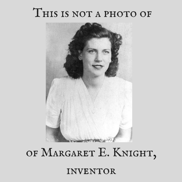 |
| Left: This is not the Margaret Knight you are looking for
If you Google 'Margaret Knight rotary engine' this is the picture that is usually coupled to the name. However Knight died in 1914 at the age 76 of and this woman has clothes and a hair style that only became popular some 30 years later than that.
I'm not quite sure what's going on, but I suspect dirty work at the crossroads. Perhaps someone thought that a pretty but fake picture would inspire young ladies to emulate her in STEM. If you are considering it, bear in mind that Margaret's estate at her death was valued at less than $300.
This version of the picture has been annotated. Not by me; other people have noticed the avalanche of fakery. Bill Todd searched YouTube, and found that the videos before about 5 years ago do not use an alleged photograph of Margaret but only drawings (poor ones!). After that, they all use the young woman's image.
Be warned!
Note the two 'ofs'. What can it all mean?
When Googling, be aware there are a lot of Margaret Knights out there; look for Margaret Eloise Knight.
The photograph that was displayed here recently proved to be the wrong Margaret Knight; my apologies.
|
 |
| Left: The Margaret Knight rotary steam engine from patent 720,818 animated: 1903
This fine animation is by Bill Todd
|
THE PEARSE-IEVERS ENGINE: 1903
 |
| Left: The Pearse-Ievers compound rotary steam engine: 1903
This engine has four chambers with rotating lobes, of increasing sizes, ambitiously aiming for quadruple expansion of the steam and thus (in theory) higher efficency. Quadruple expansion was sometimes used in large reciprocating marine engines, where the highest possible efficiency was required, but it was not normally used ashore. The low-pressure cylinder had to be very large.
This engine is unknown to Google and so was presumably not successful.
Note that 'Ievers' is not a misprint for 'Levers'. The two patentees lived in Buenos Aires, Argentina.
|
 |
| Left: The Pearse-Ievers compound rotary steam engine: 1903
Figure 13 is a section from the side, while Figure 14 is a view from above with the top half of the casing removed. The blue areas are the four cylinders containing the rotating lobes.
|
Harry PEARSE was born in Plymouth, Devonshire, in 1862, worked on the Great Western Railway at the Swindon Works and then at the Hammond Electric Light Company in London. In 1888 he was appointed Chief Draughtsman at Campana Locomotive Workshops of the Buenos Ayres & Rosario Railway, promoted to Acting Locomotive Carriage & Wagon Superintendent in 1890 and confirmed in 1891. In 1902 he became Chief Mechanical Engineer of the combined Central and Rosario Railways, a position from which he retired in February, 1911. Harry Pearse died at Addo, Cape Province, in 1931.
Eyre Francis IEVERS was on 10 April 1873 in Tonbridge, Kent, son of Eyre Ievers (1846-1926) and Jane Perrier Osbourne. He was educated at Tonbridge Castle (preparatory, 1880-1884) and the Tonbridge Grammar School (1884-1887). His apprenticeship was at the locomotive works of Neilson & Co. in Glasgow (1887-1890) following which he studied at the Crystal Palace Engineering School (1890-1891) and Kings College, London
(1892-1893) while working as an improver at a Great Eastern Railway running shed.
In 1893 he went to Argentina, employed by the Buenos Ayres & Rosario Railway as a draughtsman in their workshops at Campana (1893-1895.) For the next two years to 1897 he was a District Locomotive Superintendent, then Works Manager (1897-1898), Assistant Locomotive Superintendent
(1898-1901) and Acting Locomotive Superintendent (1901-1902).
In 1901 he returned to England where he was manager of the Eyre Smelting Co., London, from 1902 to 1904, and export manager for the Galena Signal Oil Co. from 1904 to 1908. In 1908 he was back in Buenos Aires as partner in Percy Grant & Co., engineers and representatives of manufacturers of machinery, rolling stock and other railway equipment.
Eyre F Ievers died 8 December 1958. Ievers was elected MIMechE on 21 July 1909.
From: Who was Who in Argentine Railways, 1860-1960.
THE PALINDROME ENGINE: 1906
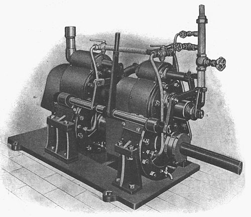 |
| Left: The Palindrome compound rotary steam engine.
The operation of the Palindrome engine is rather enigmatic, as no diagram of the internals was published in my source, but there was a lengthy description in the text. There was a rotary piston and a rotary valve, coupled with spur gearing to rotate in opposite directions at the same speed. The piston had a flat vane, and the valve a hollow cylinder, rotating on a fixed tube through which the steam entered. There does not appear to be a major breakthrough in technology here.
|
It is not quite clear what the picture represents- it looks more like two identical engines coupled together rather than a compound engine, which would presumably have one rotor casing obviously bigger than the other. The larger bottom part of the casing no doubt contains the rotor, and the smaller section above it the rotary valve. There is another even smaller housing above that, which may or may not be interconnected with the reversing lever- possibly it contained a stop valve.
Why 'Palindrome'? Well, a palindrome is a word or phrase that reads the same in either direction. This is presumably a reference to the fact that the engine was reversible, though this was by no means the first reversible rotary steam engine.
From the article: "Great things are expected from the engine by the inventors, and a syndicate is, we understand, being formed for the purpose of exploiting the invention."
The inventor, or at least one of them, appears to have been a Mr Bruce.
"Mr Bruce will be pleased to show these engines under steam to any reader by appointment at Miller's Wharf, Lower East Smithfield, London East. (near Tower Bridge)" Not for the first time, Tower Bridge is associated with rotary steam engines. See The Tower Engine. These are deep waters, Watson.
From Model Engineer and Electrician, 1906
THE ELLIS ENGINE: 1906
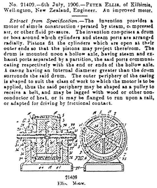 |
| Left: The Ellis rotary steam engine.
The Ellis engine is of the common eccentric-rotor moving-vane type. Its only real point of interest is that it originated from New Zealand. This info is extracted from the patent specification, No 21409.
Apologies for truly dire image quality.
Source unknown #6
|
THE CHRISTIE ENGINE: 1906
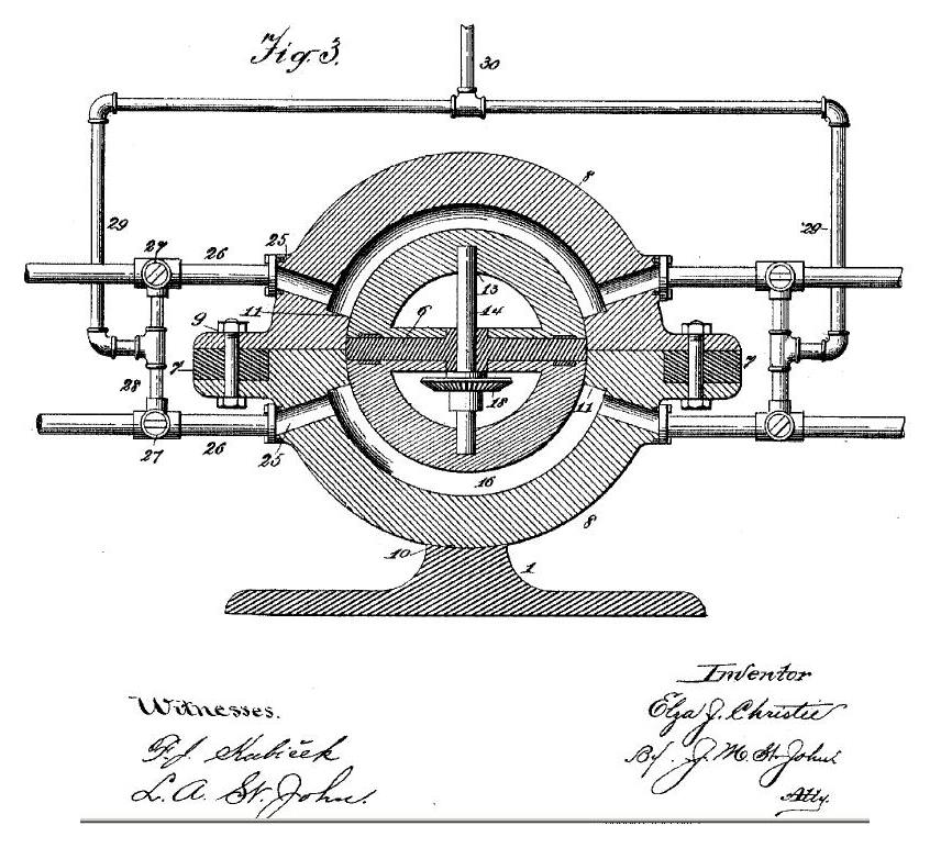 |
|
Above: The Christie rotary steam engine. Source: US Patent 814,018 dated 1906
|
Once again, it would be easy to fill pages with patents for rotary engines that never got built; therefore some extra point of interest is needed. This patent was by Elza J Christie, of Marion, Iowa, better-known for his giant monowheel. This info is extracted from the US patent specification; otherwise history is silent on the fate of this engine.
The construction and operation of this engine appears to very complicated, and for the time being I am just going to refer you to the patent document. Good Luck.
 |
| Left: The Christie rotary steam engine animated
Fortunately Bill Todd is made of sterner stuff than I am, and he has produced this superb animation of the Christie engine.
|
Christie took out other patents: US 596,480 is for a "Unicycle" which is actually the forerunner of his giant monowheel. He also took out a patent in 1904 for "A Motion Transmitter" which was an unexciting infinitely-variable transmission using cones and friction-wheels; see US patent 776,455.
THE CUMMINGS ENGINE: 1907
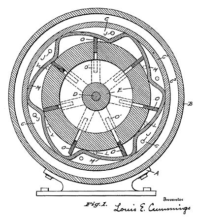 |
| Left: The Cummings rotary steam engine: 1907
The intended operation of the Cummings engine is hard to fathom, even after reading the patent. There are steam inlet ports J and exhaust ports L.
Louis E Cummings (of St Joseph, Missouri) was granted US patent No 861,164 in July 1907. Apart from the patent no trace exists of him on Google so it would appear the idea did not prosper.
This info is extracted from US patent No 861,164. (1907)
|
THE BLEECKER ENGINE: 1907
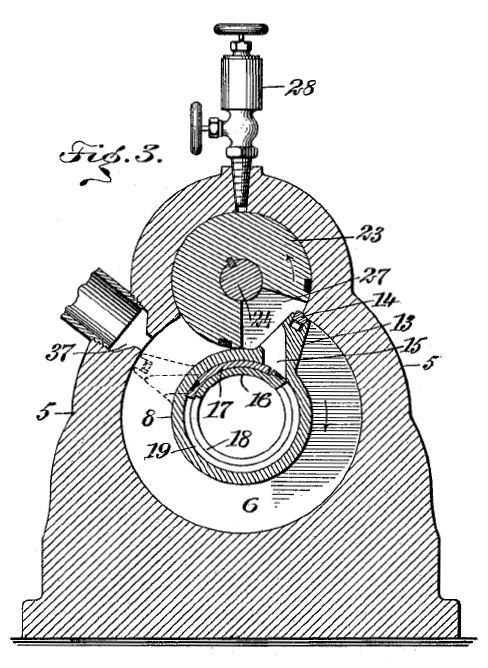 |
| Left: The Bleecker rotary steam engine: 1907
A US patent for this engine was granted to Warren Floyd Bleecker of Victor, Colorado, in September 1907. One-third shares were assigned to his brothers Frederick and Martin.
"In the upper part of the casing there is a rotary abutment..." which is labelled 23 in the drawing, and has a cutout to permit the radial wing 13 to pass. This abutment is coupled to the main output shaft by a pair of spur gears. 28 is an oil-cup lubricator. 37 is the exhaust port.
The Bleecker engine is unknown to Google apart from the patent and this website, so it did not thrive.
From US patent 865,964
|
THE KEATS ENGINE: 1909
 |
| Left: The Keats rotary steam engine
Robert Keats of Portsmouth, England puts forward another version of Pappenheim's cogs. The restricted passages for steam entry and exit look rather dubious, but that would be the least of the problems, which include no expansive use of steam and the usual sealing difficulties.
This info is extracted from UK patent specification, No 25,388. (1909)
|
THE LEE-BROWN ENGINE: 1910
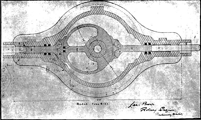 |
| Left: The Lee-Brown rotary steam engine
This engine was designed and built by Herbert Lee and John Bryden Brown of New South Wales, Australia, in 1910.
Two slipper pads push against the eccentric rotor, presumably kept in contact with it by external compression springs pushing on the two plungers. The slipper pads rock on the ends of the plungers, rather than swivelling, to maintain close contact with the rotor, but how that rocking motion could be sealed is not clear.
|
The Lee-Brown engine is here described in an extract from the Minutes of proceedings of the Engineering Association of New South Wales, for 9th June 1910. Most of the paper was devoted to the subject of steam turbines, but this section at the end dealt with rotary-piston steam engines:
"...Besides the bladed type of rotary engine, other engines of the hollow piston type, such as the Hult, manufactured by the Hult Brothers, of Stockholm, who were awarded a gold medal in the year 1897 for the rotary engine of this type, and who claim that their engine used as little as 48 lbs of steam per brake h.p. per hour, and thought
it a wonderful result. In this wonderful country of ours- Australia- the outside world would scarcely believe that we have such inventive genius amongst us as could invent and obtain patents for a rotary engine that would beat, in steam consumption, the results of the Hult Brothers' researches. We have, however, such a man in Mr. Herbert Lee, of Kensington."
Note that the Hult engine clearly had a worldwide reputation at this point.
"The author, by Mr. Lee's courtesy, was enabled to take a trip in a very bargey sort of a launch, in which was installed a small rotary engine, having a 7-in. diameter piston, with a 5-in. face, the launch fitted with a 20-in. propeller, and with 100 lbs steam pressure travelled at the rate of five to six miles an hour in this boat. The claim is 35 lbs. steam per I.H.P. Mr. Lee has lately, in conjunction with Mr. John Bryden Brown, a member of this Association, perfected this invention, and conjointly they are manufacturing these engines in Sydney. By the courtesy of the manufacturers, the B.C.L. Company, the author nas been allowed to place on the table practically the whole of one of these engines. This engine is claimed to be a 20-h.p. engine. Plate XXII., Figs. 1, 2,
and 3, respectively show section and plan of the engine; the latter showing the regulating valve.
Messrs. Lee and Brown have informed the author that they would be extremely pleased for any members of this Association, by appointment, to visit the manufacturing works and inspect this engine, and it is quite possible they would also be prepared to have some of the members present when brake tests are being carried out."
This extract is taken from Mr James Schirra's contribution to the discussion after the paper had been read:
"...The turbine is a rotary engine in a sense but it cannot be called a piston engine. Before it got so popular, nearly every inventor was working at a rotary engine; he thought there was not an ingenious mechanic but had some notion of inventing one. They nearly all worked on the same basis-a cylindrical casing and eccentric piston with sliders (really, the slider is the piston) This can be made to go round, certainly, but there is usually a great waste of steam. A great many small fittings and packings are needed to make it steamtight, and there is a great- deal of friction. He noticed a large grease-cock on the engine shown; it would never do for a condensing engine if you wanted to recover the condensed steam for feed you would want a large oil filter, anyway."
 |
| Left: Animation of the Lee-Brown engine
This shows how the slipper pads rock on the ends of the sliding plates. This would seem to make any sort of sealing there very difficult.
Another fine animation by Bill Todd
|
THE WHEELER ENGINE: 1911
The Wheeler engine is one of the select number of rotary engines that were actually built, went into some sort of production, and were apparently sold.
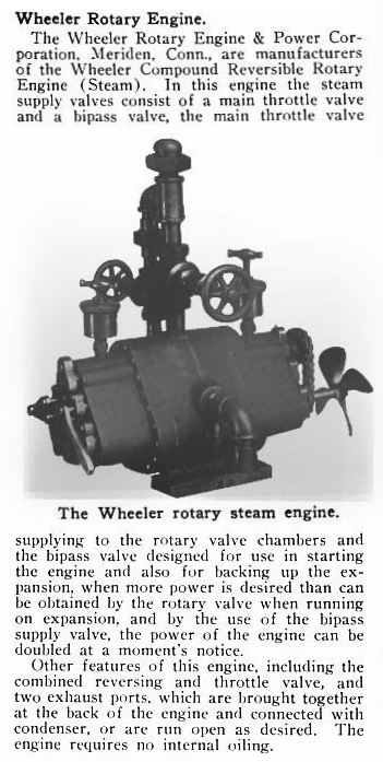 |
| Left: The Wheeler Compound rotary engine: 1911
This engine was given a brief article in the US magazine MotorBoating, shown here. It looks as if steam enters at the top through the stop-valve, and the exhaust is on the side of the casing. The two large screw lubricators hint at some difficulties with friction, despite the statement that the engine requires no internal oiling. The engine is reversible, which is essential for marine use, and according to the text could also be run simple (ie with HP steam admitted to the LP part of the engine) for greater power with less economy; probably this was controlled by the smaller handwheel.
The throttle and reversing lever is at the extreme left of the engine. The impractically short propellor shaft was presumably for demonstration purposes only.
The chain at right drives the rotary steam admission valve (see below) from the output shaft, both running in the same direction. However, in Wheeler's patents the drive is by spur gears which would rotate the valve in the opposite direction.
William W Wheeler (of Meriden, Connecticut) was granted US patent 788,179 in 1905, US patent 935,079 in 1909 and US patent 982,329 in 1911. The first was for a vane-type rotary rngine, but the last two covered gear-type engines as shown here.
From MotorBoating Dec 1911 p88
|
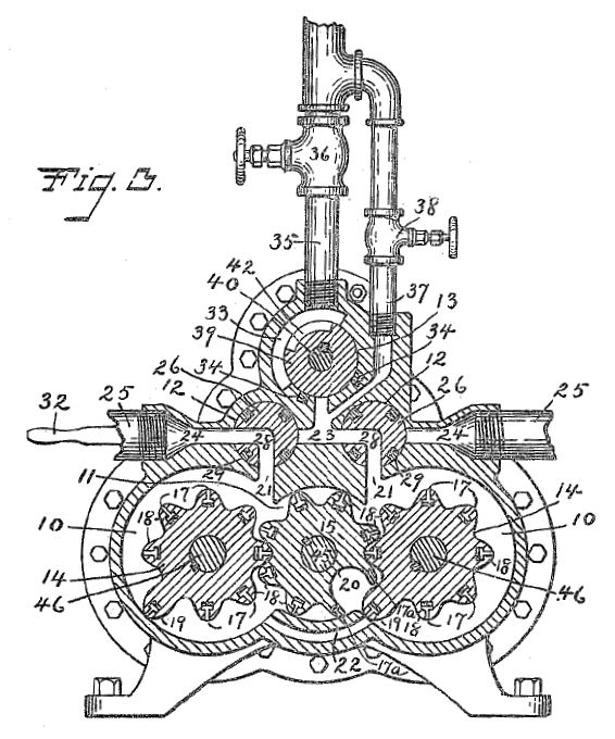 |
| Left: The internals of the Wheeler engine: 1911
The explanation of its operation in US patent 935,079 is lengthy and far from clear, but basically it is another gear-wheel engine, with two expansion chambers marked 10. The HP chamber is on the right and the LP on the left, with steam passing from one to the other through passage 22. In reverse the roles of the chambers are interchanged. Reversing was accomplished by turning the rotary valves marked 26, so that the exhaust came out of the right pipe marked 25 rather than the left.
Part 40 is a rotary steam admission valve that rotates at the same speed as the output shaft; exactly what this does and how it interacts with the cog-wheels is unclear from the patent. Part 38 is the valve which admits steam to the LP cylinder when high torque is required.
According to this patent a pretty hefty flywheel was required on the output shaft, but there is no sign of it on the photograph above.
From US Patent 935,079, Sept 1909
|
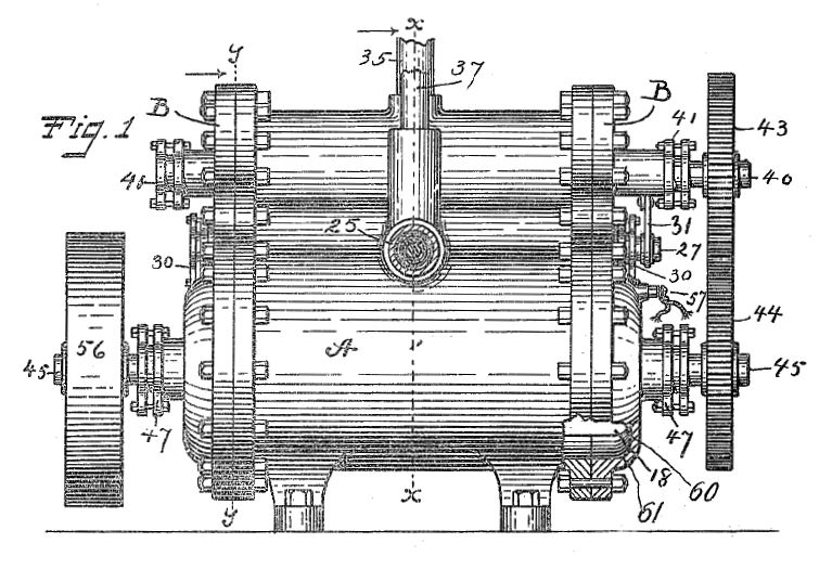 |
| Left: Side view of the Wheeler engine: 1911
This shows the gears 43,44 that drove the rotary admission valve in the top of the casing. 25 is an exhaust steam pipe, and 35 the main steam supply pipe. One of the advantages of the rotary steam engine is supposed to be its smooth torque, and one cannot help wondering why the heavy flywheel 56 was required.
Wheeler and the Rotary Engine & Power Company are, apart from this one entry, unknown to Google, which would indicate the company did not prosper even slightly.
From US Patent 935,079, Sept 1909
|
THE MCEWAN ROSS "ROTA" ENGINE: 1912
 |
| Left: The McEwan Ross "Rota" rotary steam engine
Some further details on this machine have recently been uncovered.
Firstly, I have for some time described this as the "McEwan & Ross" engine, but it appears that Mr McEwan Ross was just one person.
Secondly, the internal arrangements are now known in detail. See below:
From The Book of Modern Engines by Rankin Kennedy. Volume 2, p19. Pub Caxton Publishing Company, London, in 1912.
|
 |
| Left: Section of the McEwan Ross "Rota" engine.
The eccentric shaft e-e rotates around the central shaft b-b, carrying around the four cross-arms. The four pistons move up and down these arms, inside the eccentric cylinder d. This causes the spaces between the pistons to expand and contract, and filling and emptying these volumes with steam generates rotation. Cylinder d rotates with the pistons, minimising their relative velocity.
Now this looks a bit more like it. There appear to be no line contacts which make sealing virtually impossible, but instead broad areas at the outside ends of the piston which could be effectively sealed with something like piston rings. Also, the rotating cylinder should reduce friction and wear.
From The Book of Modern Engines by Rankin Kennedy. Volume 2, p19. Pub Caxton Publishing Company, London, in 1912.
|
 |
| Left: Side section of the McEwan Ross engine.
Steam enters via the hollow support column on the left, and leaves via the column on the right.
From The Book of Modern Engines by Rankin Kennedy. Volume 2, p19. Pub Caxton Publishing Company, London, in 1912.
|
 |
| Left: Animation of the McEwan Ross engine
This shows how the volumes between the pistons expand and contract due to the eccentric mounting of the shaft carrying the cross-arms.
This most excellent animation is kindly provided by Bill Todd.
|
 |
| Left: Animation of the assembled McEwan Ross engine
This most excellent animation is kindly provided by Bill Todd.
|
 |
| Left: How to dismantle your McEwan Ross engine
This most excellent animation is kindly provided by Bill Todd.
|
THE BROWN ENGINE: 1912
The Brown design is described in a book dated 1912 as "the last and best attempt on a practical scale". It certainly wasn't the last rotary steam engine, but this does seem to suggest that it enjoyed some success. However, this is contradicted by a statement at the end of the description saying "...the number of reciprocating parts is great, and it did not come into practical use". This is resumably the same A F G Brown that came up with the Brown Expansive Engine in 1891, judging by the similarities of the internals. See above.
Note that the cylinder is mostly surrounded by incoming steam and is thus steam-jacketed. Steam-jacketing improves efficiency with normal steam engines by reducing condensation, but I think that would be the least of your problems here.
 |
| Left: The Brown rotary steam engine; cross-section.
Naming of parts:
C cylinder
ED exhaust door
EP exhaust port
P piston
PS packing springs
S output shaft
SP steam port
SV steam valve (admission)
VS valve shaft (admission)
SS spiral springs
From The Book of Modern Engines by Rankin Kennedy. Volume 2, p16. Pub Caxton Publishing Company, London, in 1912.
|
 |
| Left: The Brown rotary steam engine; section in plan. This diagram gives a better view of the sealing arrangements.
How it works:
The steam is admitted by rotation of the left steam-valve SV.
The piston rotates under this pressure, the steam from the previous admission leaving via the right exhaust-port EP, while the right exhaust-door ED maintains the sealing (?) of the piston.
On the second half of the piston's revolution, the same actions occur with the right-hand steam-valve SV, and the left exhaust door and exhaust ports.
This seems very unpromising to me, with all those heavy doors banging in and out; it's not exactly free of reciprocating parts, as noted at the time. It also looks as if it would be impossible to reverse it, as the rotor seal would catch on the noses of the exhaust doors.
A one-door version of the engine could also be built.
From The Book of Modern Engines by Rankin Kennedy. Volume 2, p16. Pub Caxton Publishing Company, London, in 1912.
|
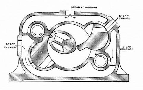 |
| Left: The Brown Rotary Expansive Engine
This is a cleaner view of the cross-section of the engine, without all the arrows and lettering. It is not a copy as there are small differences such as the extra exhaust port at top right.
Note the admission valves are here much larger in diameter than in the patent drawing.
Source unknown
|
 |
| Left: The Brown rotary steam engine animated.
Bill Todd tells me that the exhaust doors "accelerate like mad, even though Brown has attempted to use a smooth cam profile. They are effectively controlled by the edge seal as it sweeps within millimetres of the door's pivot." This would presumably add to the wear on the seal, if it has to provide the forces to waggle the heavy doors back and forth at speed.
This most excellent animation is kindly provided by Bill Todd.
|
THE MARKS ENGINE: 1912
 |
| Left: The Marks rotary steam engine; cross-section.
A is the main rotor, with two vanes, and B and C are auxiliary rotors that rotate at the same speed, synchronised by external gearing, and having cutouts into which the vanes of A fitted. On the outside of B and C are two narrow channels in which steam presses these rotors inward to avoid sliding friction, and indeed the inventor claimed that there was no metal-to-metal contact inside the whole engine. If this was true it was a remarkable achievement. A small experimental engine delivered 10 HP with 80 psi steam, running at "well over 4000 rpm, and maintaining this speed without noticeable heating." a reference to the high frictional losses in the average rotary steam engine if it was packed to be steam-tight.
D, E,F, and G are rotary exhaust valves. Steam admission was by ports in the casing end-plates, passing through the wedge-shaped passages in rotor A.
This design appeared in The Automobile Engineer, date unknown. No US patent for it has been found.
From The Book of Modern Engines by Rankin Kennedy. Volume 6, p12. Pub Caxton Publishing Company, London, in 1912.
|
THE SPIRO ENGINE: 1912
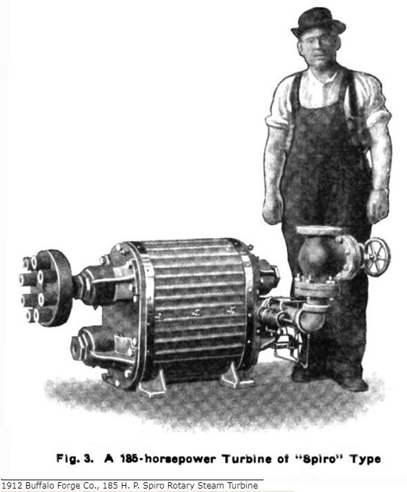 |
| Left: The Spiro rotary steam engine: 1912
This engine was promoted by its makers, the Buffalo Forge Company of Buffalo, NY, as 'The Spiro Turbine'. In fact it does not appear to have been any sort of turbine, but rather a rotary engine that worked as the inverse of the gear-wheel pump. It is very possible that the makers were trying hard to avoid the title 'rotary engine' because at this point the concept was pretty much totally discredited.
Judging by the size of the man, this 185 HP engine was quite a substantial piece of machinery, and that's a pretty big steam pipe leading into it.
No evidence of the mass production of this engine has been found. It seems likely the only ones in use were at the Buffalo Forge factory, where excessive steam consumption could be quietly overlooked.
|
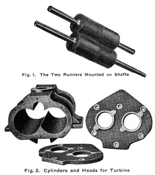 |
| Left: The internals of the Spiro rotary steam engine: 1912
The two rotors (or runners) very much resemble a pair of helical gears.
From a Buffalo Forge Company blurb:
"The runners, Fig. 1, are two sets of spiral or herringbone gears mounted so that they intermesh, the steam being introduced into the central pocket and allowed to expand until it reaches the end of the runners. This expansion takes place at a high velocity, it being figured that with 2,000 revolutions per minute and 20 teeth in a runner, there are 40,000 expansions per minute or 666 per second—the rapidity of this steam action being the dominant factor in reducing the machine to its very small dimensions."
|
It is not easy to see how exactly how this engine works. I would have expected steam leakage laterally past the outside of the runners.
|
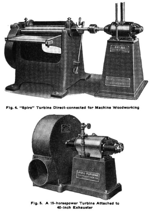 |
| Left: Applications of the Spiro rotary steam engine: 1912
From the same Buffalo Forge Company blurb:
"Fig. 4 submits the turbine direct connected to a surfacer, the illustration showing the marked feature of a high-speed source of power applied to a wood-working machine. Fig. 5 shows a 15 horsepower turbine attached to a 40-inch exhauster."
|
|
The story of the Rotary Steam Engine continues on Page 7 of this gallery.
