THE LATER YEARS: ROTARY ENGINES IN THE 20TH CENTURY.
With the introduction and development of the steam turbine, which could be regarded as the apotheosis- or more likely the nemesis- of rotary steam engines, the impetus behind the development of positive-displacement rotary engines must have been much reduced, but it did not disappear. The technology appears so seductive that it appears that people will be trying to come up with a workable rotary steam engine until the sun cools. Certainly the patents on rotary engines did not stop coming. See here for some later patents in Britain and the USA.
THE AUGUSTINE AUTOMATIC ROTARY ENGINE: 1913
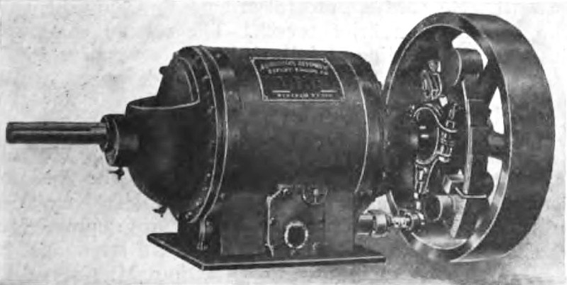 |
| Left: Fig 1: The Augustine Automatic rotary engine: 1913
This rotary engine was invented in Buffalo by Benjamin F Augustine.There is a detailed contemporary description, which is reproduced below. The 'Automatic' part of its name relates to control of speed with a governor (visible against the fly-wheel) that altered the admission cutoff.
The text below is taken from Iron Age 10 July 1913, p71
|
"A Recent Automatic Rotary Engine
A new type of automatic rotary engine, for which the special features of compactness, absence of vibration and a low maintenance cost are claimed, has been developed by the Augustine Automatic Rotary Engine Company, 1862 Elmwood avenue, Buffalo, N. Y. These engines are built in a number of different sizes from 5 up to 150 hp., and, if desired, larger sizes can be built to order. They are designed for direct connection to electric generators, centrifugal pumps, fans and blowers, etc., as well as for work in machine shops and manufacturing plants. Some of the larger units are installed on separate foundations, the connection being made through a flexible coupling. Fig. 1 is an exterior view of the engine, while a view of the rotor, showing the sliding piston blades which are the special feature of the engine, is given in Fig. 2."
"The rotating portion of the engine is made up of a cylindrical piston, A, Fig. 2, which carries the sliding blades B that move in and out on roller bearings in slots in the flanges. These blades are guided by arms, which bear in bronze bushings in the compensating balance rings. The flanges in which the sliding blades move are bolted fast to the pistons and have the telescopic disks C bolted to them. These disks set over the abutment, which is placed inside of the cylinder and in which the rotor moves. The piston, which is mounted in the abutment eccentrically with reference to the abutment bore, provides the means for the expansive working of the steam which is admitted through the pipe shown in the lower portion of Fig. 1. A Corliss type valve operated by a rocker arm and eccentric controls the admission of the steam, the position of the eccentric being regulated by an inertia shaft governor. The piston makes contact with the abutment on the priming pockets and is held there by the ring bearings, in which the shaft runs."
"As the blade passes the admission ports, which are located on one side of the central line of the bottom of the abutment, the admission valve is opened wide and steam is admitted behind the blade, forcing the piston forward until cut-off occurs, the exact point being controlled by the governor according to the load that is being carried. The steam then expands behind the blade, forcing the pistons forward until it reaches the exhaust port on the opposite side of the abutment when release occurs. The entire rotating member is carried on a shaft which runs in ring bearings located centrally with reference to the outer casing. The compensating balance rings are so arranged as to balance the centrifugal force of the blades, thus keeping the rotor steady at all times and moving the blades in and out of the grooves of the flanges so that they are kept bearing against the cylinder walls at all times with a packing strip along the edge to make a steam-tight joint."
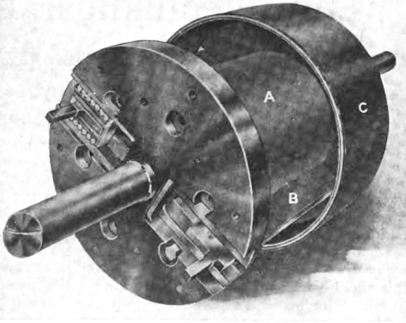 |
| Left: Fig 2: The Augustine Automatic rotary engine: 1913
"Pressure is equalized between the cylinder and the inside of the telescopic disks C, through a series of small ports in the abutment and small check valves. The pockets on the outer periphery of the abutment are thus filled at all times with steam of the same pressure as that in the cylinder and this bearing against the inside of the telescopic disks gives a floating bearing."
"In the automatic lubricating system which is used, oil is forced out through the pressure equalizing ports by centrifugal force and lubricates the running joint between the telescopic disks and the ribs on the abutment. The ends of these disks make a tongue and groove joint with the central rib running around the abutment, thus preventing leakage. The flanges bear against the ends of the abutment, making a running joint with packing rings. The piston, therefore, rotates inside the abutment, the flanges rotate against the ends of the abutment and the telescopic disks rotate in the space at the end of the abutment."
"The endwise pressure is taken by the flanges which bear against the telescopic disks so that no pressure comes against the heads. As the steam is swept from the admission port around to the exhaust port without reversal, the result is a uniflow effect and the exhaust steam is not carried backward over the cylinder surfaces."
"In a recent test made of one of these engines which was rated at 41 brake horse power, with steam at 100-psi boiler pressure, 36˝ lb. of steam per brake horsepower hour was consumed. The over-all dimensions of this engine were: length, 48 in.; diameter of casing, 17 in., and height, 20 in."
|
THE OGDEN ROTARY ENGINE: 1918
 |
| Left: The Ogden engine: 1918
Minor matters like the First World War did not stop the flow of rotary engine designs.
The Ogden engine had a two-lobed rotor keyed to a hollow central shaft. Three rotating valves (marked 3 in Fig 3 of the diagram) were rotated by spur gears from the central shaft so as to clear the way for the rotor lobes just in time. Admission and exhaust of steam was through the central shaft which had ports cut into it. The handle 19 was a combined throttle and reversing lever, reversing being accomplished by sliding the shaft with the valve ports.
It is always worthwhile inspecting the text of a patent to see if there are any clues as to whether the design was actually built. For example, the patent text for the The Hodges Engine of 1885 contains convincing indications that Mr Hodges had practical (and disappointing) experiences with rotary engines. As for Mr Ogden, he says at one point "Experience has demonstrated that the organization above described is a highly efficient one" but I suspect that was pure bluff.
Neither Mr Ogden nor his engine are known to Google.
From US patent 1,269,735 granted 18 June 1918
|
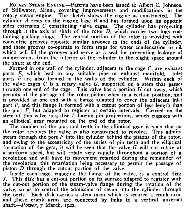
THE JOHNSON ROTARY ENGINE: 1921
 |
| Left: The Johnson engine
Rotary engine kept on coming in the Roaring Twenties. This design, by Albert Johnson of Minnesota, has two so-called valves G that interface with the main rotor D and seal it. To make this work they are driven at a variable speed by an elliptical gear on the main shaft; I would have though that would require some very precise kinematics to get anything like a seal.
Since the segments G do not appear to cover the inlet ports F at any point in their rotation it is hard to see how they can be called valves. According to the text there is an attached control disc J which actually opens or covers the inlet ports, but this is not shown on the drawing to the left. The exhaust ports are labelled E.
From Proceedings by the United States Naval Institute, Volume 48 Part 1, May 1922, pages 840-842
|
 |
| Left: The Johnson engine animated
Another brilliant animation by Bill Todd. The bizarre elliptical gears can be seen in ghostly white outline. The movement of the disc controlling steam admission can just be seen in the white slot under the right-hand valve.
Note that Bill has had to remove the hook-like protrusions on the piston in order to make it work at all. This strongly suggests that Mr Johnson never built his engine.
|
 |
| Left: The Johnson engine described
But no news as to whether it was actually built or not.
A little research shows that the US patent granted to Albert Johnson was No 1,389,874 on 6th September 1921.
From Proceedings by the United States Naval Institute, Volume 48 Part 1, May 1922, pages 840-842
|
THE CHAPMAN ORBITAL ENGINE: 1973
Originator: Howard R Chapman (California, USA)
This engine was a "steam engine" powered by Freon. It was intended as part of a bottoming cycle to improve the efficiency of conventional IC engines.
|
Above: The Chapman engine attached to a conventional IC engine. The eccentric rotor does not rotate; radial sliding seals create six working chambers.
Inlet and exhaust are by multiple valves not shown here. The six things with a star at one end are the cranks that restrain the rotor from rotating; the stars represent the bevel gears that drive the rotary inlet valves- see picture just below. Each seal only wiped a small part of the periphery. They were pressed against the inside of the casing by compression springs.
Image from Popular Science, Jan 1976
|
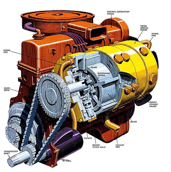 |
| Left: The Chapman engine mounted on its host internal-combustion engine, and coupled by chains to the output shaft. Note that the relatively low-speed Chapman engine needs to be geared up to match the IC engine output rpm.
Freon vapour is admitted by rotary valves, and leaves by poppet exhaust valves. The former were driven by gears on the multiple cranks restraining the rotor. How the exhaust valves were actuated is not known.
Image from Popular Science, Jan 1976
|
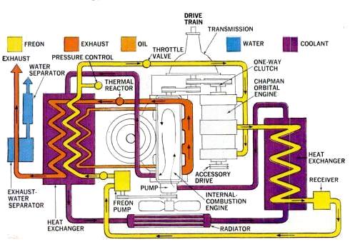 |
| Left: The Chapman engine in its bottoming cycle.
Three hot fluids- engine cooling water, lubricating oil, and the exhaust gases- pass through the boiler (heat exchanger A) and boil the Freon. This generates power as it expands in the Chapman engine. The Freon is then condensed in heat exchanger B by the engine cooling water that has just left the radiator.
Image from Popular Science, Jan 1976
|
Unlike some bottoming-cycle projects, the Chapman operation received no government funding. Its history is currently unknown, but it is clear that Chapman did not make thing easy for himself by attemping to make a satisfactory rotary engine at the same time as exploring the novelty of automotive bottoming cycles. At least one other bottoming-cycle project, by Thermo Electron, (which did receive government funding) used a three-stage turbine running at 60,000 rpm.
See United States Patent 3,743,451, "Rotary Engine", published 1973
This engine should not be confused with The Chapman Engine of 1810.

THE HENRY ENGINE: 2000.
 |
| Left: The internals of the Henry engine. Reproduced by permission.
The Henry engine is mainly aimed at exhaust heat recovery from combustion engines, ie a bottoming cycle.
The aims of the Henry Works are:
- An engine with a higher efficiency than turbines of the same power rating.
- A design which is less expensive to produce than a turbine.
- Similar smooth running characteristics as a turbine.
- A simple design which is easy to repair or service in the field.
- Ability to handle wet steam due to its robust parts and slower speeds (3000 RPM).
- Higher efficiency over much of its RPM range making speed control less critical than in turbines.
See The Henry Engine. (External link)
|
And now... some unique pictures of the Henry rotary engine prototype undergoing testing.
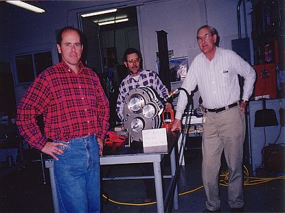 |
| Left: First run of the P-4 Henry engine in January 2000.
Personnel: Mike Taggett, George Gubler and Merrill Harker.
Reproduced by permission
|
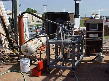 |
| Left: Early field tests of the Henry engine at a boiler company in Tulsa, Oklahoma.
Reproduced by permission.
|
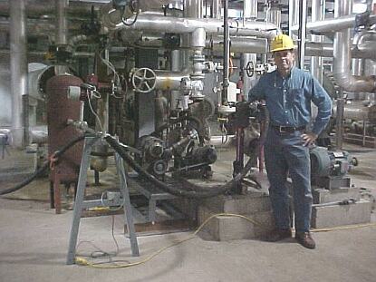 |
| Left: Mike Taggett with "Henry P-4" installed at an Ethanol plant in Minnesota.
The engine is powering a 7 HP pump. P-4 accumulated 250 running hours here in January, 2003.
Reproduced by permission.
|
Update from Mike Tagett, April 2011:
"My engine work has been on hold for a while until we can improve efficiency... we did operate an engine at an ethanol plant some years ago for 2 weeks at 150 psia...efficiency pretty poor...about 45 lbs/hp/hr We made good progress with sealing material though..."
"A rotary steam is such a simple but difficult problem... I do think getting to piston type efficiencies (70% isentropic?) is possible with the right engine materials, flow characteristics, seal materials and valving... I hate seeing poppet valves on a rotary but they do work well it just defeats the overall purpose of smooth rotary action. I think there could be an application in the 5-100KW range for a combined heat and power system (co-gen). steam quality and water quality become issues too."
THE LYNX ENGINE: 2009
Perhaps surprisingly, Youtube is a fruitful source of unconventional engine videos. Here is the Lynx engine, uploaded to YouTube in September 2009:
 |
| Left: The Lynx engine being prepared for steam test
The Lynx Engine video
This engine is one of those most unpromising designs with a vane or flap (the white thing at the bottom of the cylinder) that bashes back and forth as the engine rotates. It is shown working from live steam, but apparently it sometimes needs a push to start. The rotational speed is only about 100 rpm.
Steam comes in at the left through the armoured hose, entering the cylinder through ports under the flap. The exhaust ports are at the bottom of the cylinder just to the right of the flap, and the exhaust leaves via the brass pipe going off to the right.
There is another video; a "high-speed" steam test of the Lynx Engine. Doesn't seem to be going round that fast to me; you can clearly hear the flap rattling. It's not a strobe effect as the steam is moving normally.
This seems to be the relevant website: Lynx Steam Engines. As of July 2017 the website has disappeared, but the two YouTube videos are still there. I think we will hear no more of the Lynx engine.
|
THE QUADRUM ENGINE: 2010
One of the problems of the rotary steam engine is finding a use for it. They're not going to be replacing the superbly efficient and reliable turbines in our power stations, and steam cars are not going to make a comeback. For most requirements for rotary power, you just specify an electric motor; and electric motors are pretty sophisticated these days.
Over the last few years it has occurred to several people that there might be a niche application in Combined Heat and Power. CHP typically runs a conventional IC engine on diesel or biomass producer gas, turning an alternator to generate electricity, and using the hot water from the IC engine cooling circuit and exhaust gases for central heating. However you can also burn wood to create steam in a boiler, use a rotary steam engine to drive the alternator, and use the condensate and boiler flue gases for heating.
You have probably spotted the snag; you need an extra component- the boiler. Certainly a successful rotary steam engine would be simpler than an IC engine, but a steam boiler is a serious piece of engineering that needs skilled maintenance and safety certification. Nevertheless the idea has had recent promoters such as Quadrum.
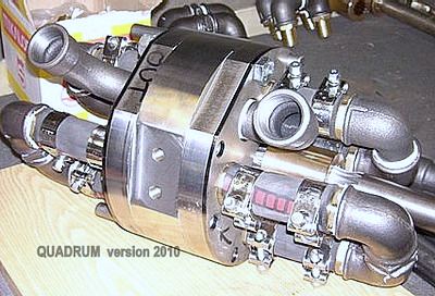 |
| Left: The Quadrum engine in 2010
Quadrum is a Finnish company. It calls its engine a Steam Motor.
The engine is one of the select few that have actually been built and tested. See the video on the Quadrum blog page. (Last updated in May 2016) I have dated the engine from the year of its first successful test run, on 9th August 2010.
|
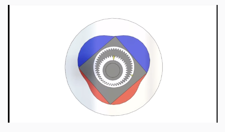 |
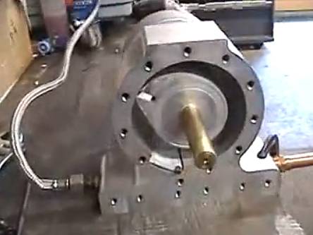
| Left: Inside the Quadrum engine
The square rotor moves eccentrically inside a three-lobed cylinder, with its rotation controlled by the gearing. This is reminiscent of the Cooley engine
More picture of the engine and its associated boiler can be seen here.
|
THE SMALLENERGY ENGINE: 2013
The SmallEnergy Rotary Vane Engine has also been built and tested.
 |
| Left: Three versions of the SmallEnergy engine
The basic principle is two vanes in a cylinder, moving so that the spaces between them expand and contract. This is reminiscent of the Stocker engine and the McEwan Ross "Rota" engine. Exactly how these vanes move is unclear, but apparently involves non-circular gears, which is not the first time these have appeared in the rotary engine story.
A PDF giving more information can be seen here. It appears to be the only info available via Google.
|
ROTARY STEAM ENGINES ON YOUTUBE
Getting back to Youtube, here is a small sample of the rotary steam engines displayed.
 |
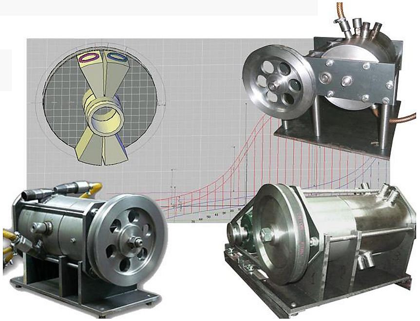
| Left: The Maguire engine on steam test: uploaded to YouTube in 2013
This engine was designed and built by Don Maguire.
You can see the video here. A speed of 2700 rpm was reached at 80 psi steam pressure. Steam can be seen blowing out of the right-hand bearing; according to Mr Maguire, this test was done with no seals fitted, and I have to wonder why. It is noisy, apparently due to the sudden release of exhaust steam that is still under significant pressure.
|
 |
| Left: The Maguire engine internals: uploaded to YouTube in 2010
A still from an earlier video shows the inside of the engine.
The principle is essentially the same as that of the Eve engine of 1825.
|
The rotary engines I have seen on YouTube generally have two things in common:
- Firstly they are very noisy, which would seem to suggest poor kinematics with parts bashing into each other.
- Secondly, they are shrouded in clouds of steam when operating, indicating poor sealing and inevitable inefficiency.
This is the end of the historical section of the Rotary Steam Engine wing. Go back to The Rotary Steam Engine Index for more general information.


