Gallery opened: 31 Mar 2019
Updated: 23 Apr 2020
More info


THE AUGUSTINE AUTOMATIC ROTARY ENGINE: 1909 |
Gallery opened: 31 Mar 2019 |
The Augustine rotary engine is unusual because it is well-documented and went into at least limited production. Here it gets its own page.
![]()
THE AUGUSTINE AUTOMATIC ROTARY ENGINE: 1909
This engine uses the familiar principle of a sliding vane in an eccentric cylinder. The idea goes back at least as far as 1839; see the Woodhouse engine.
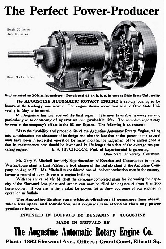
 | Left: Advert for the Augustine Automatic rotary engine: 1909
| ||
THE AUGUSTINE ROTARY ENGINE WITH AUTOMATIC CUTOFF GOVERNOR AND BALANCED PISTONS"For developing a large amount of power in a small space, the Augustine Rotary Engine has proved itself well adapted and in many plants has shown itself to be a practical working machine requiring little attention and giving good satisfaction. It has a number of novel features worked out through years of experiment by the inventor, Benj. F. Augustine, who is President of the Augustine Automatic Rotary Engine Co, of Buffalo, NY. |
REGULATION
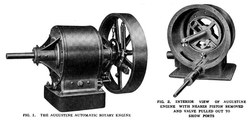
"Illustrations herewith show the action of the engine and the design on which its success depends. In Fig. 1 is seen the assembled engine ready to run. It has a flywheel governor of special design which controls the speed accurately between no load and full load by changing the position of the eccentric."
"This eccentric drives by means of an eccentric rod and rocker arm the oscillating valve, the driving mechanism being shown on the base of the engine in Fig. 1 and also at the bottom of the engine casing, Fig. 2. In Fig. 2, the ports through which the valve admits steam are in the bottom of the casing, one of them being seen where the revolving piston on the near side has been removed."
 | Left: Advert for the Augustine Automatic rotary engine: 1909
|
PISTONS
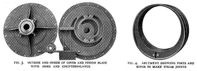
"The pistons revolve. They are 2 in number with flanges at the ends and between the 2 pistons, giving steam-tight joints. These flanges fit down on either side of the abutments and are the full size of the bore of the outer casing. In each piston is a counter-balanced blade seen in Fig. 1, the blade being at the lower right hand side of the piston and the counterbalance in a slotted arm of the piston at the upper left hand. This blade laps across the flanges of the piston so that the pressure of the steam seals them and makes a tight joint. These blades have, as shown in Fig. 3, a long arm on one side and a short arm on the other and on the ends of these arms, as shown in Fig. 2, are crossheads which run in grooves in the covers as indicated in Fig. 3, to keep the blades traveling central with the bore of the cylinder."
"STEAM ACTION
As the piston blade crosses over the lower center of the engine, the valve rocks to open the port and admit
steam behind the blade; this forces the revolving piston around and the valve rocks to cut off steam at the point required by the load, as indicated by the governor action."
"From this point of cutoff, expansion takes place and when the blade on one side reaches its uppermost position, the blade on the other side crosses the lower center and that piston begins to take steam. Thus one cylinder always has steam expanding while the other is taking steam at initial pressure. Steam exhausts without the action of a valve when the blade crosses the opening to the exhaust port shown in the abutment, Fig. 4."
"Care has been taken to provide steam-tight joints at all points. On the inside edge of the abutment is a packing ring to bear against the flange on the piston. At the bottom of the abutment is a packing block to prevent any possible circulation of steam from the live steam to the exhaust steam side of the piston. The outer edges of the blades make, of course, a steam-tight joint with the abutment at all times. These joints are arranged to take up their own frictional wear and the careful design of the engine and the balancing of all parts is such as to reduce wear to a minimum."
"The ends of the blades are housed in by the flanges of the pistons so that leakage cannot occur past these ends, and carrying the ends of the blades through to the crossheads which run in the heads or covers, insures accurate travel of these blades and freedom from vibration. The exhaust of the engine is so arranged that admission of steam and expansion take up about 320 deg. of the circle of revolution, and exhaust the remaining 40 degrees. The arrangement of the governor and valve is such that the engine can be reversed at any time and when running at any speed."
"An idea of the compactness of the engine is had from the dimensions of 3 sizes. The 20-hp. has a height of 18 in. and a base 14 by 15 in., while the 45-hp. has a height of 27 in. and a base 20 by 24 in. A 100hp. engine recently installed in the planing mill of the Dodge-Bliss Co., at Tonawanda, N. Y., is 36 in. high, has a base 32 by 40 in., and a 4-ft. flywheel."
"Shop tests of the engine made on Mar. 20, 1909, at 95 to 102 lb. pressure, with the generator giving 110 volts and 104 to 112 amperes gave a water consumption of 622 lb. per" hour at 21 hp. and 631 lb. at 22 hp., or an average of 29 lb. an hour a horsepower. Five amperes was reckoned as the equivalent of an engine horsepower and all water was condensed and weighed."
![]()
THE AUGUSTINE AUTOMATIC ROTARY ENGINE: 1910
This is another article about the 1909 engine as described above. Some of the illustrations are the same but of better quality.
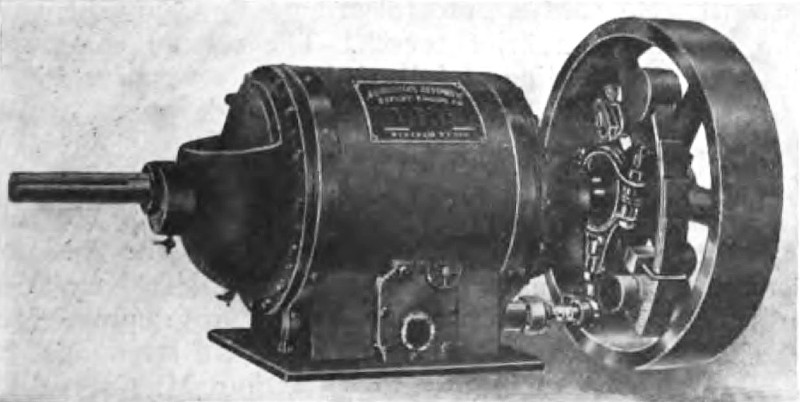
 | Left: Figs 10, 11. The Augustine Automatic rotary engine: 1910
|
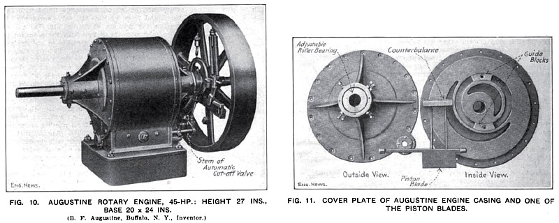
"It is stated by the makers, the Augustine Automatic Rotary Engine Co., 73.8 Ellicott Square. Buffalo, N. Y., that half-a-dozen or more of these engines, of from 10 to 20 HP., have been put into regular and satisfactory operation driving blowers, etc., and one larger engine, of 100 HP., has been installed at a saw mill. A 45-HP. Engine of this type. Shown in Fig 10, is 27 ins. high and stands on a 20 x 24-in. base."
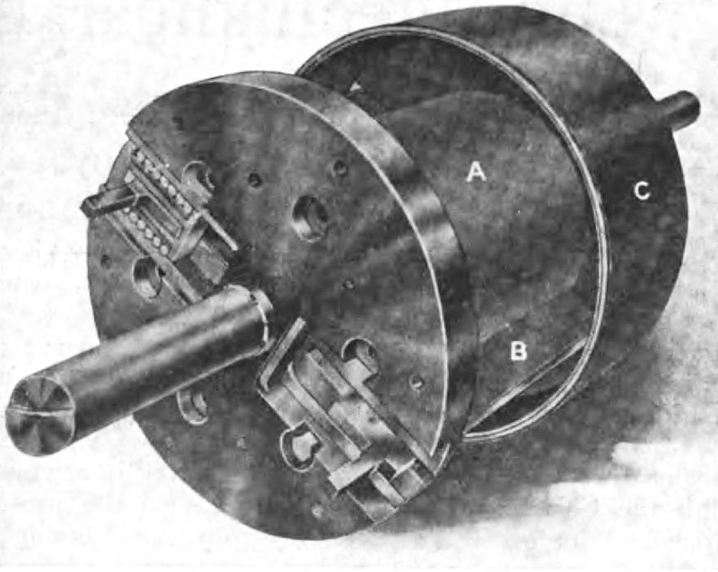
 | Left: Figs 12 a,b,c: The Augustine Automatic rotary engine: 1910
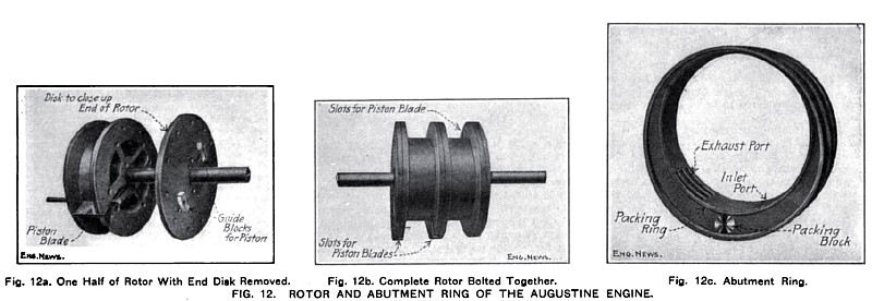
"The construction of the Augustine rotor is shown in Figs. 12a and 12b. In its assembled form, it consists of a hollow cylindrical cast-iron drum with projecting collars, or flanges, at each end and at mid-length. Each end of the hollow drum Is closed up by a cast-iron disk. The three flanges really serve as the side walls of two annular cylinders and also serve to support the piston blades when they are extended beyond the body of the rotor." |
"One of the piston blades is shown in Fig. 12a in position in the slots in the rotor flanges. Each of the two blades is balanced by a counterweight attached to two rods extending inward from the blade across the axis of the rotor. The form of the counterweight is shown in Fig. 11."
"The two abutment rings, one of which is shown in Fig. 12c, are of the proper width to fit into the spaces between the flanges on the rotor. When assembled, the outer edges of the rings are even with those of the rotor flanges, and the under side of the body of the rotor Is in contact with the inner surface of the rings. The inner face of the ring forms the fourth wall of the annular cylinder space, whose other three walls are formed by the drum and flanges of the rotor itself. The opening through the ring is eccentric to its outer circumference so that the area of cross-section of the cylinder space gradually increases from zero, at the point of contact with the rotor at the bottom, to a maximum at the top. The piston blade is made to travel in a circle concentric with the eccentric opening by means of the curved guide blocks shown in Figs. 11 and 12a. which slide in circular slots in the cylinder cover."
Packing rings around the edges of the eccentric opening (Fig. 12c) are required to prevent leakage between the ring and the rotor flanges. As a further precaution, a "packing block" is placed between the ring and the flanges just below the point of contact of the ring and the rotor drum. This packing block is intended to prevent the passage from the pressure side over to the exhaust side of any possible leakage past the packing ring.
The abutment rings and rotor are enclosed in a plain cylindrical casing, whose two heads, or end covers, contain the roller bearings for the shaft. No stuffing boxes on the shaft are necessary in the Augustine engine. One-half of the rotor drum and one abutment ring are shown in position in the casing in Fig. 13. The shaft journals are made adjustable (see Fig. 11) so that the rotor drum can be brought down to the proper contact with the abutment rings.
The grated exhaust through the abutment ring (Fig. 12c) communicates with that shown in the casing in Fig. 13, which in turn is connected with the exhaust pipe. The cut-off valve is a hollow cylinder turning in a cylindrical chamber near the bottom of the casing. Steam is admitted through slots in the valve to corresponding slots through the walls of its chamber, whence it enters the cylinder through the inlet port in the abutment ring. In Fig. 13, the valve has been pulled out from its working position to show the ports. The cut-off valve is given an oscillating motion by an eccentric on the engine shaft and the point of cut-off is controlled by a fly-wheel governor.
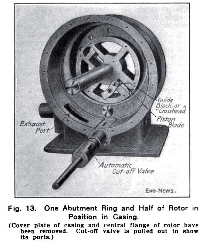 | Left: Fig 13: The Augustine Automatic rotary engine: 1910
The rotor is show in Fig. 13 in about the position where admission occurs. The contact of the rotor drum with the abutment ring obstructs the escape in that direction of the entering steam, which therefore turns the rotor by pressing against the projecting piston blade. After cut-off, the rotor continues to revolve under the expansive pressure of the steam until the blade passes over the exhaust valve and the steam is permitted to escape. Revolution continues, under the action of the fly-wheel and of the second piston blade in the other half of the rotor, and the piston passes the point of contact with the abutment ring and is ready for the next stroke. The pistons in the two annular cylinders, separated by the middle flange on the rotor, are diametrically opposite so that both cannot be at the dead-point at the same time. | ||
TESTS |
THE AUGUSTINE AUTOMATIC ROTARY ENGINE: 1913
This is a new engine, a development of the 1909 engine. It can also be seen on Page 9.
 | Left: Fig 1: The Augustine Automatic rotary engine: 1913
|
"A Recent Automatic Rotary Engine
A new type of automatic rotary engine, for which the special features of compactness, absence of vibration and a low maintenance cost are claimed, has been developed by the Augustine Automatic Rotary Engine Company, 1862 Elmwood avenue, Buffalo, N. Y. These engines are built in a number of different sizes from 5 up to 150 hp., and, if desired, larger sizes can be built to order. They are designed for direct connection to electric generators, centrifugal pumps, fans and blowers, etc., as well as for work in machine shops and manufacturing plants. Some of the larger units are installed on separate foundations, the connection being made through a flexible coupling. Fig. 1 is an exterior view of the engine, while a view of the rotor, showing the sliding piston blades which are the special feature of the engine, is given in Fig. 2."
"The rotating portion of the engine is made up of a cylindrical piston, A, Fig. 2, which carries the sliding blades B that move in and out on roller bearings in slots in the flanges. These blades are guided by arms, which bear in bronze bushings in the compensating balance rings. The flanges in which the sliding blades move are bolted fast to the pistons and have the telescopic disks C bolted to them. These disks set over the abutment, which is placed inside of the cylinder and in which the rotor moves. The piston, which is mounted in the abutment eccentrically with reference to the abutment bore, provides the means for the expansive working of the steam which is admitted through the pipe shown in the lower portion of Fig. 1. A Corliss type valve operated by a rocker arm and eccentric controls the admission of the steam, the position of the eccentric being regulated by an inertia shaft governor. The piston makes contact with the abutment on the priming pockets and is held there by the ring bearings, in which the shaft runs."
"As the blade passes the admission ports, which are located on one side of the central line of the bottom of the abutment, the admission valve is opened wide and steam is admitted behind the blade, forcing the piston forward until cut-off occurs, the exact point being controlled by the governor according to the load that is being carried. The steam then expands behind the blade, forcing the pistons forward until it reaches the exhaust port on the opposite side of the abutment when release occurs. The entire rotating member is carried on a shaft which runs in ring bearings located centrally with reference to the outer casing. The compensating balance rings are so arranged as to balance the centrifugal force of the blades, thus keeping the rotor steady at all times and moving the blades in and out of the grooves of the flanges so that they are kept bearing against the cylinder walls at all times with a packing strip along the edge to make a steam-tight joint."
 | Left: Fig 2: The Augustine Automatic rotary engine: 1913
|
 | Left: Advert for the Augustine Automatic rotary engine: 1913
|
THE AUGUSTINE ROTARY GAS ENGINE: 1912
We are veering off the subject somewhat here, but it appears that Augustine abandoned work on rotary steam engines in 1913 and turned his thoughts to internal combustion engines. His first 'rotary gas engine' appeared in 1912 and was an internal-combustion version of his rotary steam engine.
A later rotary gas engine in 1918 was rotary in a different sense- it was a radial engine with (relatively) conventional cylinders and the whole engine rotated around a stationary crankshaft. It was a six-cylinder engine.
![]()

|