Vibratory engines have oscillating pistons in cylinders of peculiar design. These machines appear to combine the disadvantages of both rotary and reciprocating engines, and it is not surprising that they were not only unsuccessful, but have sunk into the deepest obscurity. Here they are unearthed.
Since the time of the engines displayed here, the word "vibrate" has shifted in meaning. Then, it was roughly equivalent to "oscillatory", and did not have the modern connotation of a high-frequency small-amplitude movement that is usually (but not always) unwelcome.
The vibratory engine may have vane pistons very like those of a rotary engine, but they oscillate back and forth rather than turning steadily. A connecting rod and crank will therefore be required to get rotary motion, with all the disadvantages of reciprocating masses that need balancing. The sealing problems are at least as severe as for the rotary engines.
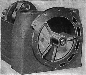
THE ELIJAH GALLOWAY VIBRATING MARINE ENGINE: 1829
|
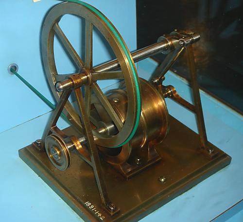
| Left: A Model of The Elijah Galloway Vibrating Marine Engine.
This is the Elijah Galloway who designed at least two rotary steam engines; see
the Elijah Galloway engine of 1840, and
the Elijah Galloway engine of 1846
The cylinder contains a vane which oscillates through 270 degrees. The valvegear is not modelled, but was intended to be on top of the cylinder, and actuated by an eccentric on the main shaft.
The design of this engine was described in Galloway's patent of 1829. I have so far found nothing to indicate that it was actually built at full scale and tried out.
Model in The Science Museum, London. Scale 1:8. Author's photograph.
|
|
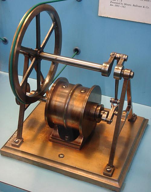
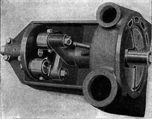
| Left: The other side of the Model.
The sliding link and connecting-rod convert the oscillation of the cylinder crank into continuous rotation of the output shaft above the cylinder.
In the best traditions of the Science Museum, the model works very nicely when you press a little brass button.
Model in The Science Museum, London. Scale 1:8. Author's photograph.
|
THE CAMBRIAN STEAM ENGINE: 1841.
It has taken a long time, but I have finally tracked down the "Cambrian System" referred to below. It was introduced by Mr John Jones, of the firm of Aspinall, Jones & Co, an engineering company in Smethwick. He was granted a patent on the 7th of April, 1841.
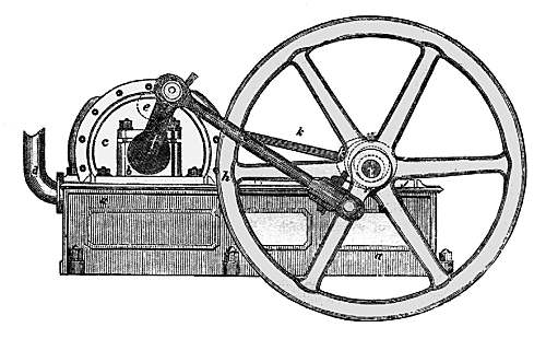
Source: Mechanics' Magazine for 2 July, 1842
|
| Left: A Cambrian engine
The vibratory pistons are inside the drum on the left. The arm marked k drives the valves from an eccentric on the crankshaft.
|
|
| Left: Vertical Section through Cambrian engine
The vibratory "pistons" or rather vanes are the horizontal structures across the middle of the drum. The valve v oscillates to control steam admission through the pipe on the left and exhaust through the pipe on the right.
The cross-connecting passages w and w' allow the steam to press on the top surface of one vane while also pressing on the bottom surface of the opposite vane, being roughly equivalent to two double-acting cylinders in a conventional engine. The central shaft passed through stuffing boxes on each side of the drum.
The triangular abutment marked o has a seal pressing against the central shaft, with an adjusting screw to take up wear, like many rotary engine engines; the sealing problems are much the same.
|

|
| Left: Horizontal Section through Cambrian engine
The pistons or vanes are marked g. They seem to be drawn with a grossly excessive clearance from the sides of the drum.
|
|
| Left: Vertical Section through a three-vane Cambrian engine
Mr John Jones included in his patent the possibilty of making similiar engines with three or four vanes, presumably with the intention of increasing the power density of the machine, ie, how much power you can get from a given volume of machinery. Since adding vanes would appear to reduce the possibilities of expansion, it is doubtful if this was really a good idea. Note the three steam spaces marked g.
Now there are three screws to adjust the sealing pieces.
|
According to a Mr H Crossley, who appears to have part-owned the intellectual property of the Cambrian system, it "...has, by its invariable performances during the last two years and a half, given the utmost satisfaction." (From Mechanics Magazine Saturday June 1st, 1844)
It is possible, of course, that he was not completely impartial in the matter.
LOCOMOTIVE VIBRATORY ENGINES: 1841
This locomotive, and three others, were built using the Cambrian system. The information on these locomotives has been expanded and moved to
the Vibratory Locomotive gallery in the Locomotive wing of the Museum.
 |
| Left: A development of the Jones design?
This is the "Albion", an 0-4-2 built by Thwaites Bros of Bradford in 1848, for the South Yorkshire Railway. It is supposed to have run there for some 15 years, which would seem to indicate it was successful, though I do wonder if it might have been converted to a conventional layout during that time.
The transverse cylinder between the two driving axles was fitted with "vibrating vane pistons" which oscillated on the central shaft. There appears to be conventional Stephenson valvegear just to the left of the central shaft. (arrowed)
|
THE PENNY MECHANIC ENGINE: 1842
|
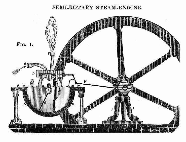
Above: The Penny Mechanic vibratory engine: crank drive to flywheel not shown
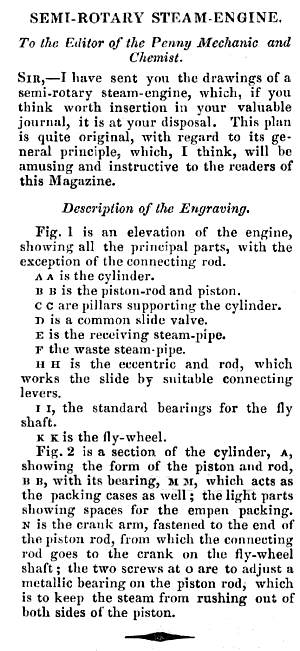
I have called this the Penny Mechanic engine because it appeared in that journal; a description was attached (see below) but the name of the inventor was not given.
The transverse cylinder A contains a vane piston G swinging back and forth on shaft B. On top of it is a slide valve D driven from an eccentric on the flywheel shaft via rod H. The piston drives the flywheel by a crank N (in Fig 2 below) and connecting rod. (This is not shown in Fig 1) Steam inlet is via E, and the exhaust steam is shown emerging at F.
From The Penny Mechanic and Chemist for Saturday 10th Dec 1842
|
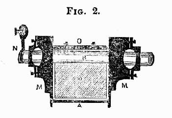 |
| Left: A section of the cylinder of the Penny Mechanic engine
Note provision for packing the bearings at M,M, with 'empen' presumably meaning hemp. O is a metallic packing piece pressed against the shaft by two screws. Good luck with getting the adjustment of those right.
In other words we have the usual sealing problems that afflicted both vibratory and rotary engines.
From The Penny Mechanic and Chemist for Saturday 10th Dec 1842
|
 |
| Left: The published description of the Penny Mechanic engine.
Note that there is no name attached.
The obvious question arises, is this the same as the Cambrian engine, described above? While the general layout is similar, there are signficant differences:
The Cambrian engine has a centrally-pivoted vane piston that makes it double-acting, while the Penny Mechanic engine has a single vane, like the Ericsson engine shown below.
The Cambrian engine has a rotary steam-distribution valve, while the Penny Mechanic engine has a slide valve. (which might well have worked better)
This does not prove that Penny Mechanic engine was a separate invention, or even that it existed at all. The anonymous correspondent says only that he has sent drawings; if he had constructed the engine, you would think he would have mentioned it. I suspect this was a purely theoretical engine, almost certainly based on either the Cambrian engine, or the Elijah Galloway engine.
From The Penny Mechanic and Chemist for Saturday 10th Dec 1842
|
 |
| Left: Advertising the Penny Mechanic
A few months back I discovered a few issues of The Penny Mechanic and Chemist at a book fair; I had never seen it before. It seems to have been a rival to the better-known Mechanic's Magazine, and was published in exactly the same small-booklet format. It was published by D A Doudney in London, statrting in November 1836; the ad on the left appears in a bound volume covering the first year. Whether that is an actual depiction of D A Doudney or just a stock engraving is not currently known.
Google offers us the Reverend D A (David Arthur) Doudney who wrote his memoirs in 1894. Since that is 58 years later it seems unlikely to be the same person unless he took up publishing the Penny Mechanic at a very young age.
|
THE VIBRATING MARINE ENGINE OF JOHN ERICSSON: 1843
This remarkable marine engine was the creation of the Swedish engineer John Ericsson, and was fitted in the American steamer USS Princeton, the USA's first screw-driven steam warship, and the world�s first screw steam warship with its boilers and engines entirely below the waterline for protection from enemy fire; hence the low profile of this engine. The 164-ft vessel of 954 tons (700 tons in another account) displacement was ship-rigged.
John Ericsson is better known for producing the USS Monitor, an early ironclad which fought a famous if inconclusive battle with the ironclad CSS Virginia of the Confederate States Navy, during the American Civil War, and also for the Ericsson caloric ship which was powered by enormous hot-air engines.
The engine was variously called a 'vibrating piston', 'vibrating pendulum' or 'semi-cylinder' type. The idea was actually not new; it was anticipated by Elijah Galloway's patent of 1829, described above. It drove a six-bladed screw of 14-ft diameter. Cautious guesstimation suggests it developed 250 ihp, giving the Princeton a speed of 7 knots. The engine was built by Merrick & Towne of Philadelphia.
|
| Left: Ericsson's Vibrating Engine: end view.
The left cylinder is sectioned to show the oscillating vane and the steam ports. Note the small packing piece bearing on the top of the piston shaft. The angularity of the two connecting rods prevented dead-centre problems.
The valve chest can be seen below the left cylinder; the valves were driven by eccentrics on the rotating crankshaft.
From Bizarre Ships of the Nineteenth Century, by John Guthrie. Pub Hutchinson 1970.
|
Small cranks at the aft end of each cylinder worked a condenser air pump and the usual water pumps for boiler feed etc.
|
| Left: Ericsson's Vibrating Engine: plan view. Aft is at the top.
The engine was constructed in 1841 by Merrick and Towne from Ericsson's designs. Apparently it much impressed the engineers of the time, and when the Princeton's hull was worn out (after only seven years, which is rather strange) the engine was fitted into a new hull. However, no other such engine was built, so there must have been a snag somewhere. From examining the troubled history of rotary steam engines, it would seem certain that this topology would have sealing problems, needing packing that either caused excessive friction or allowed too much steam leakage, and required frequent adjustment.
From Bizarre Ships of the Nineteenth Century, by John Guthrie. Pub Hutchinson 1970.
|
The Princeton was commissioned on the 9th September 1843. She arrived at Washington DC on 13th February 1844. She was armed with two massive 12-inch muzzle loaders, one of them called "Peacemaker" and of defective design. On a pleasure and trial trip down the Potomac on February 28, 1844, she carried President John Tyler, (one of the lesser-known USA presidents) his Cabinet and some two hundred guests on board. The gun was ceremonially fired several times in the afternoon. Several hours later, Captain Robert F. Stockton was convinced by the crowd on board to fire one more shot. This time the defective gun burst. It instantly killed Secretary Upshur; Secretary Gilmer; Captain Beverly Kennon, Chief of the Bureau of Construction; Virgil Maxcy of Maryland, Charge d'Affaires to Belgium; and the President Tyler's valet, a black slave named Armistead. It also injured about 20 other people. Tyler was unhurt, having remained safely below deck.
|
| Left: Ericsson's Vibrating Engine
The two oscillating vanes move out of phase, presumably with the intention of smoothing out torque variations. Note the early style of propellor with long blades.
Stupendous animation by Bill Todd, to whom many thanks.
|
There is a Wikipedia article that gives more details of the Princeton's career. She was broken up in 1849 after decay was found in her timbers that it was uneconomic to repair. The sound timbers and the unique engines were used to build a second vessel called USS Princeton. New boilers and propellors were fitted. The second Princeton was decommissioned and sold in 1866, the fate of the engines being currently unknown.
This engine should not be confused with the famous Ericsson's Vibrating Lever engine, which powered the famous USS Monitor. It was of relatively conventional design, with horizontal trunk pistons. Like the vibrating vane engine, the aim was to reduce the height of the engine and allow it to be mounted below the waterline.
|
| Left: Ericsson's Vibrating Engine
This animation gives a close-up of the sealing arrangements in the cylinders.
Another great animation by Bill Todd.
|
SOUTTER & HAMMOND SEMI-ROTARY ENGINE: 1848
|
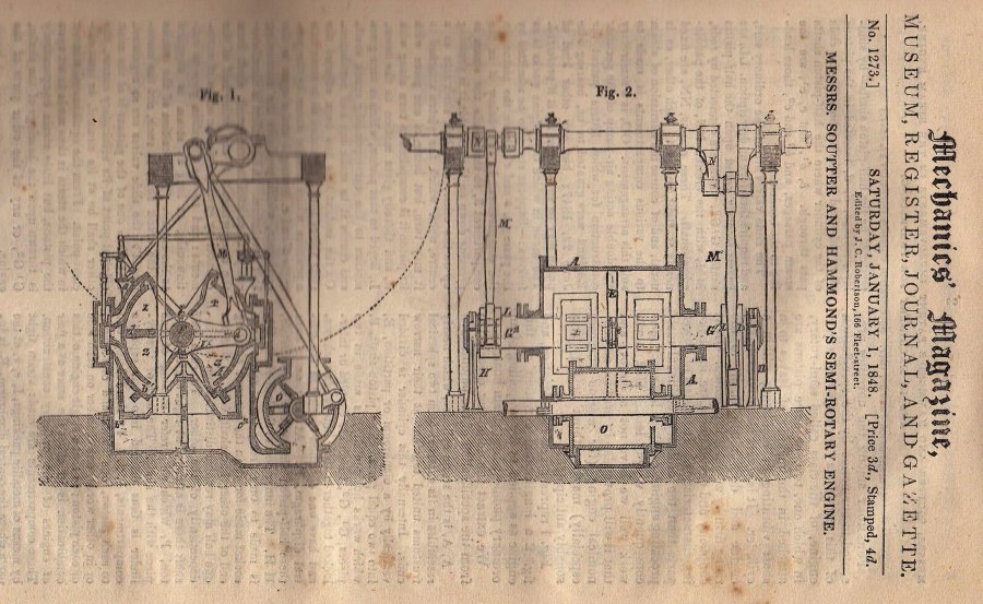
| Left: Soutter & Hammond Semi-rotary Engine: 1848
This remarkable vibrating engine appeared on the cover of Mechanics Magazine for 1 Jan 1848.
There are two double-acting flap chambers; these appear to be of the same size so compound operation was not intended. Each flap chamber has its own slide-valve, operated by an eccentric on the crankshaft via system of levers. Below and to the right is a double-acting vane-type air pump to maintain condenser vacuum.
It appears the engine was intended for marine propulsion. A British patent was taken out, which was the basis for the article in Mechanics Magazine. The author said that success "...may we think be very reasonably anticipated." However there was no indication it was actually under construction, and apart from the article Google is silent on the Soutter & Hammond engine.
Soutter & Hammond had had their 'Pneumatic Tilt-hammer and Pile-driver' described in Mechanics Magazine for 13 June 1846.
|
BATES COMPOUND VIBRATING ENGINE: 1899

|
| Left: Bates Compound Vibrating Engine.
"The upper section of the cylinder has a shorter radius than the lower section for the compound effect. The shaft and wings are concentric and vibrate between two stationary abutments, 10, 10. Opposite each abutment is a cylindrical valve, which by its motion admits the steam to the upper section, and transfers its exhaust to the lower section, and also the final exhaust."
The oscillating "pistons" are 13 and 14. The steam is distributed by two valves 5 at each end; presumably these also oscillated. Steam enters at the top and exhausts through the bottom pipe.
From "Mechanical Movements, Devices and Appliances" by Gardner D Hiscox, published by Sampson Low, Marston & Co in 1899.
|
|
| Left: Link Vibratory Engine.
"A pair of curved cylinders with an annular piston rod to which is attached the arms from the central shaft. The reciprocal motion of the piston rocks the central shaft, the motion of which is made continuous by a link and crank, not shown."
Or in other words, it is a conventional reciprocating engine made much more difficult by using curved cylinders, for no obvious reason. There looks to be a lot of wasted space.
From "Mechanical Movements, Devices and Appliances" by Hiscox
|
|
| Left: Oscillating Piston Engine. (Inventor unknown)
"A crank and connecting rod outside the engine convert the oscillating motion of the piston into rotary motion."
But just what is the point? All the sealing problems of a rotary engine, but none of the advantages.
You can see a model of this engine concept working on YouTube. It looks as if it was made from the drawing at left.
From "Mechanical Movements, Devices and Appliances" by Hiscox
|
|
| Left: A Vibrating Piston engine; Parson's Model. (1)
"Two sector pistons vibrating in a cylinder. One sector is fast on a central solid shaft, the other is fast on a concentric hollow shaft. At the other end of each shaft is a crank and link connection to a wrist pin at opposite positions on a face plate which is fast on a revolving shaft eccentric to the piston shafts. The exhaust port is in the circumference of the cylinder."
From "Mechanical Movements, Devices and Appliances" by Hiscox
Could this be Charles Parsons as in steam turbine? These are deep waters, Watson, but not wholly unnavigable to the persistent.
Before turning his attention to turbines, Parsons invented The Parsons Epicycloidal Engine. It is not the vibrating piston engine shown here, but is an interesting hybrid of rotary and radial principles; forty of the epicycloidal engines were manufactured by the Kitson's Company of Leeds in Yorkshire. Kitson's was the engineering company involved in the Kitson-Still Steam-Diesel Locomotive.
|
If Parsons tried two unconventional piston engines before applying himself to steam turbines, then there is so far no supporting evidence. Or is this engine the brainchild of another Parsons? Charles had a brother, Richard Clere Parsons, who was aso involved with engineering, being on the staff of Easton & Anderson of Erith; perhaps it was him.
Hiscox simply describes it as '"Parsons" model' but why he put the name in inverted commas is unclear. I can find no other reference to this engine apart from in Hiscox; can anyone help?
|
| Left: A Vibrating Piston engine; Parson's Model. (2)
A view of the top.
It is not clear if the original images of this engine are photographs or pen-&-wash drawings. If they are photographs, then this engine is one of the very few so recorded.
|
This engine is a classic exposition of the "pursuing-piston" concept, where two rotors go round with one at least at a varying speed, so as to form spaces that expand and contract. Whether it should be classified as a rotary or a vibrating-piston engine is an interesting point; however I for one plan to lose no sleep over the question. It stays here in the Vibratory Engine Gallery for the time being.
|
| Left: A Vibrating Piston engine; Parson's Model. (3)
Showing the principle of operation.
The sealing problems of this engine are potentially much easier to solve than those of other vibratory and rotary engines, because of the large area of piston contacting the inner surface of the cylinder, as opposed to a line contact.
|
|
| Left: A Vibrating Piston engine; Parson's Model. (4)
A Bill Todd animation shows the principle of operation; the speed variation of the sectors is produced because the two shafts are offset from each other.
This animation is kindly provided by Bill Todd
|
|
| Left: A Vibrating Piston engine; Parson's Model. (5)
From another angle, and showing the casing.
This animation is kindly provided by Bill Todd
|
|
| Left: Roots Double Quadrant Engine.
"In this design the two oscillating pistons are connected directly with the crank on the inside of the engine case, which is also the exhaust receiver. From the positions of the connecting rods at the end of the stroke of each piston the dead centre is eliminated." Steam inlet appears to be controlled by a rotary or oscillating cylindrical valve at a, while exhaust occurs when each flap runs off the end of its curved surface. The exhaust apparently exits at the left, just under the shaft of the left-hand flap.
Could this be the same Roots who came up with the Roots blower?
From "Mechanical Movements, Devices and Appliances" by Hiscox
|
|
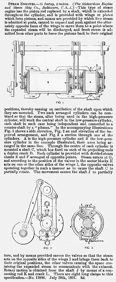
| Left: The Richardson Engine: 1891
The notion of vibratory engines for ship propulsion was still around in 1891, as this patent demonstrates. At any rate, the Richardson Engine and Steam Ship Company of Baltimore thought so. They were probably out on their own because marine steam engine design had by this time settled on vertical compound or triple-expansion engines.
However, the advantages of a vibratory engine can be seen in Figure 1; the cylinders could be laid along the axis of the vessel, parallel to the propellor shaft, and took up very little space in the vertical direction, unlike conventional marine engines of the era.
This engine is unique among the known vibratory engines because it is compound, with separate high and low pressure vibratory cylinders.
The steam inlet and exhaust valves are of the Corliss type, apparently operated by the bosses on the central oscillating shaft. This arrangement seems to rule out altering the steam cut-off point. There also seems to be no provision for reversing the engine, making it completely impractical for marine use.
From Industries 30 Oct 1891
|


