Updated: 22 Dec 2006


Updated: 22 Dec 2006
|
There are many websites dedicated solely to hot air engines, and this page does not attempt to supplant them. What it does attempt is to provide some unusual sidelights and some unique images relating to the history of these engines.
Hot air engines use the heating and cooling and expansion and contraction of air to generate power. The hot air engine was once very popular for light duties, largely because of what it did not have; a boiler. It was impossible to have a boiler explosion. Manufacturers were not slow to point this out in their advertisements, also emphasising that skilled supervision was not required. Anyone could stoke a hot-air engine.
Another advantage was that the hot air engine was quiet, as the air stayed inside the engine and there were no gasping or exhaust noises. The engine also required no continuous source of water to keep working.
The great drawback to hot air engines was and is their very limited power-to-weight ratio. The power yielded by heating and expanding air is small compared with that produced by boiling water.
Nowadays the term "hot air engine" is pretty much synonymous with the Stirling cycle in one of its configurations, but history shows that many other approaches, some of them undeniably bizarre, were also tried. Here you can learn about some of them...
According to Knight's American Mechanical Dictionary, 1880, air engines can be put into five classes:
1) Air is compressed, and then heated directly by passing it through a furnace. The hot 'air' then acts against a piston and is discharged to the atmosphere. Since the oxygen is consumed the exhaust cannot be used in a closed cycle.
2) Air is compressed, and then heated indirectly by passing it through pipes heated by a furnace, and then acts against a piston. The exhaust can be returned to make a closed cycle as it is not involved in combustion.
3) Air is held in two reservoirs communicating with each side of a piston. The reservoirs are alternately heated and cooled to apply varying pressures to the piston.
4) The air is mixed with water or steam to reduce abrasion of the moving parts, or in the hope of increasing the power output. See the aero-steam engines. (In preparation)
5) The air or gas exerts its pressure against water which in turn acts against a piston. The rationale behind this indirect method is to keep hot air, cinders etc away from the moving parts. It is also much easier to make a good piston seal for a liquid rather than a gas.
Now this is not a completely satisfactory classification; for example, there is nothing to stop engines in Category 1 or 2 from also being in Category 5. However, it will do for our purposes.
THE STIRLING CYCLE ENGINE
The Stirling cycle.
Crucial to the operation is the 90-degree phase-shift between the pistons, which makes operation hard to visualise. There is a very good animation of an Alpha engine at www.keveney.com/Vstirling.html The regenerator is essential to get reasonable efficiency.

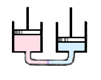
| Left: The Stirling hot air engine principle.
|
The whole essence of the hot air engine is that air is heated and cooled as efficiently as possible. The regenerator greatly improves the efficiency. Typically it consisted of a mass of iron wires through which the air passed when the displacer moved it from one end to the other. When the air was displaced from the hot end to the cool end, the regenerator was heated and the air consequently cooled. When the air was moving back to the hot end, it regained the heat temporarily stored in the regenerator.
Stirling engines are classified into three groups, depending on how the power and displacer pistons are connected.
| Left: The Alpha hot air engine configuration.
|
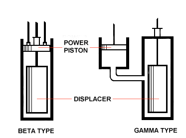
| Left: Beta and Gamma hot air engine configurations.
|

| Left: A Ringbom hot air engine
|
Left: A Rider hot air engine
|
THE EARLY YEARS
Wood Wood 1759.
Left: The Stirling hot air engine of 18xx.
|
The first practical hot air engine was built in 18?? by the Reverend Robert Stirling in 1816, though previous attempts had been made by people like Sir George Cayley around 1807. In 1816 he registered a patent for the an engine and the "Economiser".
JOHN ERICSSON AND CALORIC ENGINES
John Ericsson (1803�1889) was born in V�rmland, Sweden. He is best known for entering his steam locomotive "Novelty" in the famous 1829 Rainhill Trials, and for designing the pioneering ironclad USS Monitor in 1861, but he also spent much effort on what he called Caloric Engines. This is just another name for a hot-air engine.
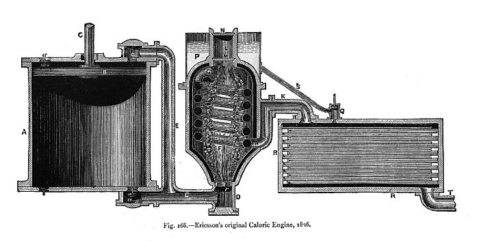
In 1826 he arrived in England with a working model engine which he called his Flame Engine. This worked with Swedish birch wood as the fuel but burnt out when fired with English coal. The image below is believed to show the gas-generating section of this engine, but this is so far not confirmed.
|
Above: Part of the first Ericsson caloric engine.
|
In 1833 London Caloric Engine.
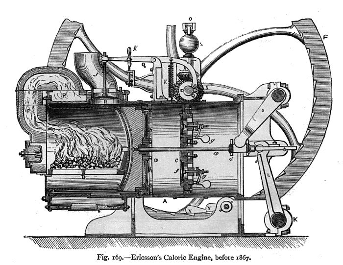
Ericsson settled in New York where he built, between 1840 to 1850, eight experimental engines using wire gauze regenerators. These engines worked on an open cycle with external heating and using two pistons of unequal diameters.
In 1851 Ericsson and his financial backers built the Caloric Ship Ericsson, a 260-foot paddle ship. The Caloric engine had four cylinders, each no less than 14 feet in diameter with a 6 foot stroke, but the power output was only BHP. The ship was not a success, and unfortunately sank in a storm off New York. It was raised and then fitted with steam engines.
Ericsson was not disheartened by the failure of the caloric ship, and went on to patent a number of improvements to his engines during the years 1855-1858. These experiments cumulatated with his improved Caloric Engine, an open cycle machine using a power piston and a supply piston, fitted with valves. This engine proved an immediate success with over 3000 being sold with in three years. This machine was sold in sizes of 8 inches to 32 inch cylinder diameters. A Caloric engine of this type was installed at the Pilot Island Light Station to power the fog signal in 1854.
Ericsson became interested in Solar power. Finding that his small caloric engine was not suitable on account of the valves he developed, around 1872, a displacer type (or Stirling) engine to work with a parabolic reflector, the intention being to use it in sunny climates to power irrigation pumps. The solar power application did not take off, but his business backers persuaded him to patent the design in 1880, as a pumping engine heated by coal, wood or gas. The engine was first built by the Delameter Iron Works and later by the Rider-Ericsson Engine Co. in sizes from 5 to 12 inch cylinder diameters.
This was the last air engine developed by John Ericsson, who turned to other interests like warships.
|
Above: Part of the first Ericsson caloric engine.
|
PHILIPS STIRLING ENGINES
The Philips company of Holland made important advances in Stirling cycle technology. Their development of the Stirling hot gas engine started in 1938, driven by a desire for a versatile electricity generator that would allow increased sales of Philips electronic products in areas with no reliable electricity supply. After the end of World War 2, the first prototypes were presented. One innovation was the rhomboid drive to the power and displacer pistons; another the roll-sock seal.
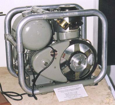
| Left: A Philips Stirling generator set: 1950s.
|
The market for an electrical generator was reduced by the introduction of the transistor, which made battery-powered radios much more practical. Today, when power is required in remote areas, diesel engines are almost universally used to drive generators.
In 1975 a horizontal 4-cylinder engine was built giving 115 hp at 3200 rpm. The working fluid was helium at the high pressure of 140 bar (2030 psi) and the engine achieved 40% efficiency.
Stirling research ceased in the late 1970s. The only enduring commercial product was the Philips Stirling cryocooler, a reversed Stirling engine that produces liquid air.
From Knight: Ericsson Stillman Roper Baldwin Messer Willcox Laubereau Peters Bickford Shearer Kritzer
PATENTS
Resonantly Coupled alpha-Stirling Cooler. Issued on September 29, 1998 as U.S. Patent 5,813,235
USAGE
Hot-air engines were once widely used for generating small amounts of power. They pumped water, turned fans, animated shop-window displays, drove dental drills and sewing-machines, and even powered gramophones and player-pianos. See The Hot-air Gramophone
Hot air engines typically had long working lives, usually ended by the iron hot end failing. The introduction of modern steels would have cured this, but by the time they were available electric motors had arrived, and the hot air engine lost its market niche.
This device is one for connoisseurs. It is not only a vacuum engine, but a rotary vacuum engine.
HOT AIR ENGINE LINKS
There is a large amount of info on the web. Here are a few selected places to look at:
http://stirlingengines.org.uk/index.htmlRobert Sier's webpage. Robert Sier is the author of an excellent book on the history of hot-air engines.
http://www.stirlingsouth.com/A large site on Stirling & vacuum engines, including lots of examples at exhibitions.
http://www.cyg.net/~freebreeze/ A Stirling-powered fan that sits on top of your stove.
http://m.webring.com/hub?ring=stirling The Stirling Engine webring
http://www.jonbondy.com/Example of a Ringbom Stirling engine
http://www.baileycraft.com/bkringpc.htmAnother Ringbom Stirling engine. Beautiful.
http://www.jerry-howell.comA source of model plans and kits
http://users.moscow.com/oiseming/lc_ant_p/lnk_stir.htmA large collection of links, some of them dead, unfortunately.
http://www.hotairengines.comThe site of Buster Brown of Yuma, Arizona. Has a large picture gallery.
www.sesusa.org/index.htmA very nice site; includes some deep theory provided by Dr. Israel Urieli of Ohio University.
www.steamengine.com.au/stirling/engines/index.htmlNice pics of Kyko, Ericsson, and Heinrici engines.
http://stirlingmotor.comA fine site: kits to build various Stirling engines, pictures, simulation programs, etc. |
SUMMARY
Advantages:
A WORD ON BOILER SAFETY.
It is often thought that the great danger with a steam boiler is explosion due to excessive boiler pressure. This is not so. That can be prevented by a simple spring-loaded safety valve, which operates quite automatically- assuming of course it has not been tampered with or incorrectly assembled and is not corroded shut.
The more deadly danger is explosion due to lack of water. If the firebox of a boiler becomes uncovered by a falling water level, it will rise in temperature to the point where the metal loses strength, and the firebox collapses. The effects can be no less fatal and destructive than a boiler explosion provoked by any other means, and automatic safeguards are much harder to provide.
