Gallery opened Sept 2005
Updated: 9 July 2020
Gerd Niephaus working model added


The Parsons Epicyclic Engine. |
Gallery opened Sept 2005 |
It was a high-speed engine designed to drive a dynamo directly. This was highly desirable as otherwise it was necessary to use belts and pulleys, which were cumbersome and subject to slipping, or gearing, which in those days was relatively crude in design, and therefore noisy and showed high frictional losses at speed.
There were two pairs of horizontally-opposed cylinders, arranged at right angles. Both cylinders and crank rotated, the cylinders at half the speed of the crank. The geometry is arranged so that connecting-rods and crossheads are not required.
Charles Parsons took out his first patent on this engine in 1877, when he was only 23 years old. This was probably Patent 2344. He took out a second patent, No 4266, in 1878.
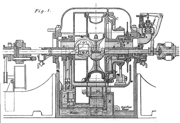 | Left: Side elevation of the Parsons engine.
|
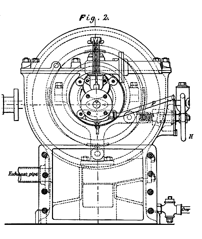 | Left: End view of the Parsons engine.
| ||||||||||||||
Cylinder diameter5 in
Piston stroke6 in
Oil pump plunger diameter1.5 in
Oil pump stroke0.75 in
Oil pump valve diameter1 in
Oil pump valve stroke0.75 in
|
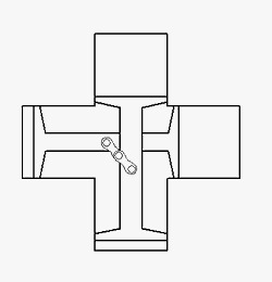
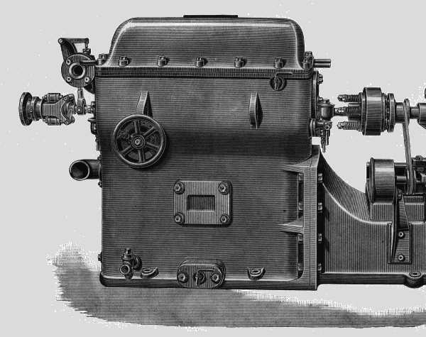 | Left: Exterior view of the engine.
|
| 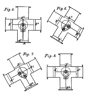
Above: A diagram of the Parsons engine that attempts to show how the epicyclic action allows the piston rods to move linearly without connecting rods.
|
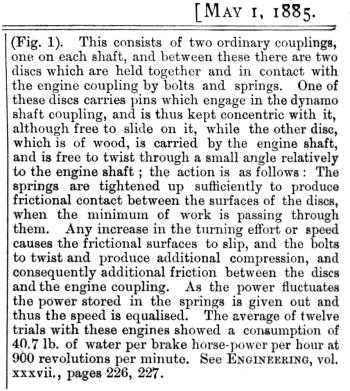
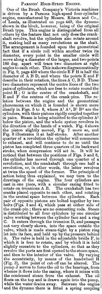
| Left: Continuation of the article from Engineering.
|
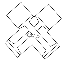 | Left: Animation of the Parsons epicyclic engine.
|
 | Left: Animation of the Parsons epicyclic engine.
|
THE HISTORY OF THE ENGINE
Parsons' epicyclic engine began as a model made of paper, sealing-wax and steel wire when he was an undergraduate at Cambridge University. It became reality while he was working as a premium apprentice at Armstrong's Elswick works from 1877 to 1884. He was allowed to continue developing the engine while he was at Elswick, providing he paod for any work done by the Works. (Thi swas probably something to do with being the son of an Earl) According to Appleyard, it was a compound engine, but in the Engineering drawings there is no obvious difference in the diameters of the two pairs of cylinders. It generated 10 hp, and drove a Siemens dynamo that for a time supplied an arc lamp on the Elswick jetty. According to Appleyard it ran at 7000 rpm, but this is almost certainly a misprint for 700 rpm.
 | Left: The Parsons epicyclic engine as shown in the second patent, No 4266.
|
The completed engine was offered to Armstrong's, but they turned it down. It was subsequently put to work driving machinery in the millwright's shop at the "Ordnance Works" which is believed to refer to Palmer's Ordnance Works at Jarrow-on-Tyne.
It was later sent to Easton & Anderson of Erith, where Richard Clere Parsons, Charles Parsons' brother, was on the staff. They used it to drive a high-speed pump, and made some more examples themselves, apparently with good results.
A few years later, R C Parsons moved to the engineering firm of Kitson's at Leeds (see the Kitson-Still locomotive) and they produced about forty epicyclic engines of varying power output in the range 10 - 20 horsepower, for driving dynamos. Some were used for electric lighting on steamships, some generated elecricity for lighting in the Kitsons offices, and most interestingly, some were sent to the Sudan to provide electric light for railway building at night. The last mentioned "were engulfed in sand" whatever that means, and no more were bought. Info from Clark
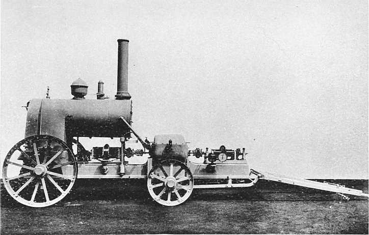 | Left: A rare, and probably unique, picture of the the Parsons engine ready for portable use.
|
The epicyclic engine was eventually eclipsed by the Willans engine for driving electric generators, and that engine in turn was superseded by the steam turbine- largely due to the work of Parsons.
The epicyclic engine should not be confused with Murray's hypocycloidal engine (In course of preparation).
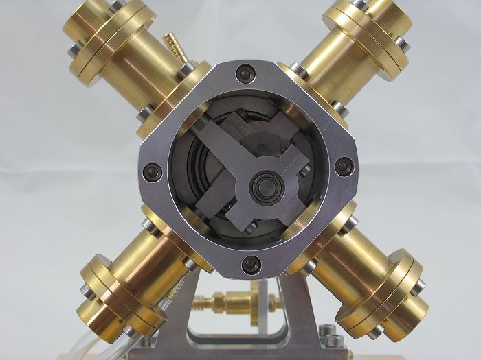 | Left: The Parsons Epicyclic Engine modelled by Gerd Niephaus
|
Bibliography:
Charles Parsons by Rollo Appleyard; published by Constable & Co of London in 1933.
Kitsons of Leeds by Edwin Kitson Clark; pub The Locomotive Publishing Co, date unclear but around 1938.
![]()

|