This gallery shows some of the truly bizarre engines that fit nowhere else; for example, the Polizzi flap engine, which looks like one of the great losers of all time. The Canda engine probably beongs on the cam-engine page, but until its internal arrangements are confirmed it stays here in Miscellanea.
Many of the engines shown here are rotary engines; in the context of aero-engines that means the engine whirls round a stationary crankshaft. That might sound odd enough in itself, but it was actually a common system in the early days of aeroplane engines. It does not mean a rotary engine in the sense of a rotary piston as used by the Wankel, nor a radial engine in which the cylinders stayed still and the crankshaft turned the propellor.

THE BRETON AERO ENGINE: 1909
This bizarre engine was shown at the Paris Flight Show in 1909.
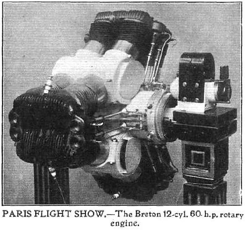 |
| Left: The Breton engine: 1909
The Breton engine propped up on a couple of elegant wood pillars. The object to the right is the stationary ignition magneto.
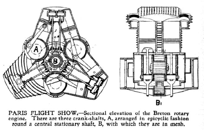
The Breton was a rotary engine; the engine rotated around a stationary shaft, and carried the propellor around with it. The peculiar design consisted of two V2 engines side by side. Three of these assemblies were mounted around a central shaft and drove it by spur gearing. Strangely the cylinders in the V2s were arranged to fire simultaneously, so the smooth flow of power theoretically possible with a 12-cylinder engine was thrown away. The cyinder heads for each set of four adjacent cylinders were a single casting.
The gearing was such that the three planetary crankshafts rotated at 1600 rpm, while the whole engine rotated en bloc at 400 rpm around the stationary central shaft, carrying around the propellor. It was supposed to give 60 HP at this speed.
From Flight magazine, 13 Nov 1909
|
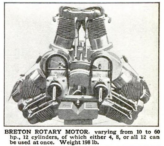
It appears the two adjacent cylinders shared a combustion chamber, as only one spark plug per pair is shown in the photograph.
Flight magazine described it thus:
Dimensions: 82 mm by 85 mm, weight, 90 kilogs, price 10,000 Francs. The size is clearly far too small, and I suspect that some English journalist unfamiliar with the metric system confused mm with cm.
 |
| Left: The Breton engine: 1909
Air was drawn into the crank-case by fans on the three crankshafts for cooling purposes; one intake can be seen as a dark slot in bottom centre of the photograph. The cylinders were finned, but not deeply.
The valves were operated by cams on the central shaft, and fuel injected into the valve-chambers by pumps worked off the valve tappet rods. The curved injection pipes can be seen in the photograph above.
From Flight magazine, 13 Nov 1909
|
The idea of multiple V-engines geared to a central shaft resurfaced in 1939, with the Bakewell Wingfoot engine, shown below.
 |
| Left: The Breton engine: 1911
The Breton Company were still around in 1910, exhibiting at a French aeronautic show; the engine now has twin magnetos, which may hint at some difficulties with the ignition system. However no reference to the engine or company has been found after early 1911.
This picture of the idiosyncratic Breton comes from Popular Mechanics for Jan 1911
|
THE CANDA ROTARY ENGINE: 1910
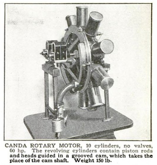 |
| Left: Canda rotary engine: 1911
The most startling feature of this engine is the total absence of cooling fins; the cylinders look like a set of tin cans. It is possible it was a water-cooled engine, but as it is a rotary engine, in which the cylinders rotate around a stationary crankshaft, getting water to and from the cylinders represents a serious problem.
According to the caption, there are no valves, which suggests a 2-stroke engine. It also says that 'piston rods and heads are guided in a grooved cam, which takes the place of the cam shaft. This makes very little sense and I suspect the writer meant 'takes the place of the crank shaft' which implies it is a cam engine like, say, the Michel cam engine.
Another question is how the carburetted air, from the carburettor in the left foreground, reaches the cylinders. The standard method for rotary engines is via a hollow crankshaft- which puts an ultimate limit on how powerful a rotary engine you can build. But here the carburettor is connected to what appears to be a curved manifold well away from the centre of the engine.
Note the twin magnetos, and the spark plugs at the bottom of the cylinders.
Apart from this image, the Canda company is unknown to Google, suggesting it did not see any success.
From Popular Mechanics for Jan 1911, which refers to the second Air Show in the Grand Palais. Paris, held in October 1910.
|
 |
| Left: Canda rotary engine patent: 1910
This is one case where seeing the patent raises as many questions as it answers. The engine is inside-out, with the spark plugs at the bottom of the cylinders. The cylinders are upside down! The connecting rod passes through what would normally be the cylinder head, but here it is at the bottom of the cylinder. There is no mention in the text of sealing here, the diagram showing none. No method of cooling is mentioned.
It is actually a four-stroke engine, effectively with a rotary valve instead of conventional valves. There are ports in the cylinders which align with apertures in a fixed plate at the appropriate times. (bear in mind that the cylinders are going round because this is a rotary engine) A spring applies axial pressure to this plate in opposition to the combustion pressure, in the hope of achieving a seal. I have my doubts.
It does indeed use a cam instead of a crankshaft, claiming as advantages the elimination of connecting rods that pivot sideways, and the possibility of arbitrary profiles, so the piston motion can be something other than sinusoidal-plus-second-harmonic. (See the Atkinson engine for an example of an engine with non-sinusoidal piston movement, which can have efficiency advantages) The latter is true, but while he has eliminated the pivot, he has not eliminated side thrust on the rods, nor has he provided any means of dealing with it.
A worrying point is that the photograph shows the cylinders closed off at the outer ends, while the patent shows them open so air can move in and out.
Perhaps the biggest mystery is how this deeply dubious design got as far as the building of a prototype. Did it ever actually run, even for a few minutes? I have nagging suspicion the photograph may be of a mock-up, without the internal cam that would have been expensive to machine. Quite possibly the cylinders were closed off with tin lids to make it look a bit less weird at the exhibition.
The engine was patented by M. Louis Canda, resident of France. He is unknown to Google.
From French patent 420,417 of September 1910, kindly provided by Pigeon. I have drawn heavily on his comments here.
|
 |
| Left: Canda rotary engine: 1911
This drawing shows a slightly more practical version of the Canda engine. There is now rudimentary finning on the cylinders, and the support for the piston-rod looks more thought-out. A bit more, anyway. The sealing of the piston rod should be do-able as it is essentially a one-dimensional sealing problem, exactly as for pistons and their rings.
However the cylinders are shown as sealed at their outer ends. Was the trapped air suppose to act as some sort of air spring?
Radial engines all have odd numbers of cylinders to allow a sensible firing order. This does not apply to rotary engines.
From the book A�rostation, Aviation by Max de Nansouty. (1854-1913) Published at Paris by Boivin et Cie, 1911.
|
 |
| Left: Canda rotary engine: 1911
Connoisseurs of this website will know Bill Todd as the source of some deeply impressive and instructive animations. However, he informs me that his software baulked at the Canda engine. This is how he put it:
"The 3D modeller refuses to animate this abortion !"
"Canda has offset his cylinders in an attempt to reduce the side load on the rod during power stroke (nothing new - it is even done in conventional engines to reduce piston to bore friction) . However the effect of this is to make the angle even more acute on the compression and exhaust strokes . To fix that requires a a reduced slope on the cam (i.e. more than a quarter turn - which might at least make enough room for all ten rods) which reduces the power stroke arc to less than 90', thus increasing the forces and negating the whole point of offsetting the cylinder 1."
|
Nonetheless Bill is not easily defeated, and he managed to produce this animation of two cylinders, which gives an idea of the cam problems.
|
THE RENAULT V4 ENGINE: 1910
 |
| Left: Renault engine: 1911
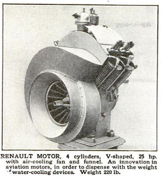
This air-cooled V4 engine has some very distinctive ducting to get the cooling air from a centrifugal fan to where it is required at the cylinders, and its odd appearance is the only reason it appears here. It apparently gave 25 HP at a weight of 220 lb.
There is however some mystery about it. Surely an air-cooled engine was not 'innovative ' in 1911? And further, why would an aviation engine need a cooling fan when it has a great big propellor whizzing round just in front of it?
From Popular Mechanics for Jan 1911, which refers to the second Air Show in the Grand Palais. Paris, held in October 1910.
|
THE BERTHAUD ENGINE: 1910
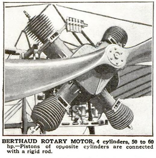 |
| Left: Berthaud rotary engine: 1911
We are told this engine has the distinction of having opposite pistons tied together with a rigid rod, but nothing about how rotary motion is produced. Possibly a scotch crank arrangement? Enquries are continuing.
This engine is unknown to Google, though other Berthaud engines are known.
From Popular Mechanics for Jan 1911, which refers to the second Air Show in the Grand Palais. Paris, held in October 1910.
|
THE BECK ROTARY ENGINE: 1910
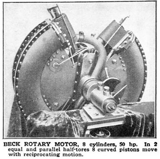 |
| Left: Beck rotary engine: 1911
This highly unconventional rotary engine uses pistons moving in segments of a toroid. It is a toroidal engine.
It is pictured here because it was at the same Paris airshow as the engines above, but in fact there is already a good deal of information about it and its history on the toroidal engine page. Earlier Beck engines had pistons moving in a complete toroid, and only later was this altered to two quarters of a toroid, as shown here.
The rounded housings at the end of each toroid segment house, one at each end, the inlet and exhaust valves. These were driven from camshafts just above and below the crankshaft. No method of cooling is shown; presumably Beck was relying on the toroid segments whirling around in the airflow. Note that there are two pairs of toroid sections joined together, which is why the piston count is eight and not four.
From Popular Mechanics for Jan 1911, which refers to the second Air Show in the Grand Palais in Paris, held in October 1910.
|
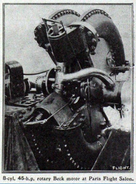 |
| Left: Beck rotary engine: 1911
The Beck engine from a slightly different angle, showing how the toroid segments are mounted side-by-side. The curved pipe appears to be an induction manifold, fed from the carburettor via a hollow crankshaft, as was the usual practice in rotary engines. It looks as though the exhaust escapes through apertures around the exhaust valve; I doubt if that would do the valve-spring much good.
Image from Flight magazine, 1910
|
THE GREGOIRE ENGINE: 1910
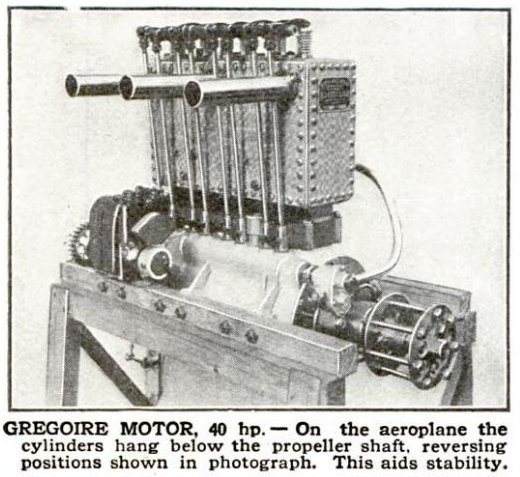 |
| Left: Gregoire engine: 1911
It has to be said that this engine has a distinctive air of crudity; in fact its New Brutalism appearance is the only reason it is included here. The water-cooling consists of a rectangular riveted box that does not promise sophistication within. Did they really need all those rivets? Was this an early attempt at cooling with water under pressure, to raise its boiling point?
It is supposed to be installed upside-down, to lower the centre of gravity of the aeroplane. Whether this would have the desired effect in an aeroplane of the era I do not know, but later engines such as the Gipsy Major ran inverted, the motivation being not stability, but improving the forward view of the pilot.
There are clearly four sets of valvegear, indicating as expected a four-cylinder engine; however there seem to be only three exhaust stubs.
Shown at Paris air show in 1910. The Gregoire engine is unknown to Google.
From Popular Mechanics for Jan 1911, which refers to the second Air Show in the Grand Palais, Paris, held in October 1910.
|
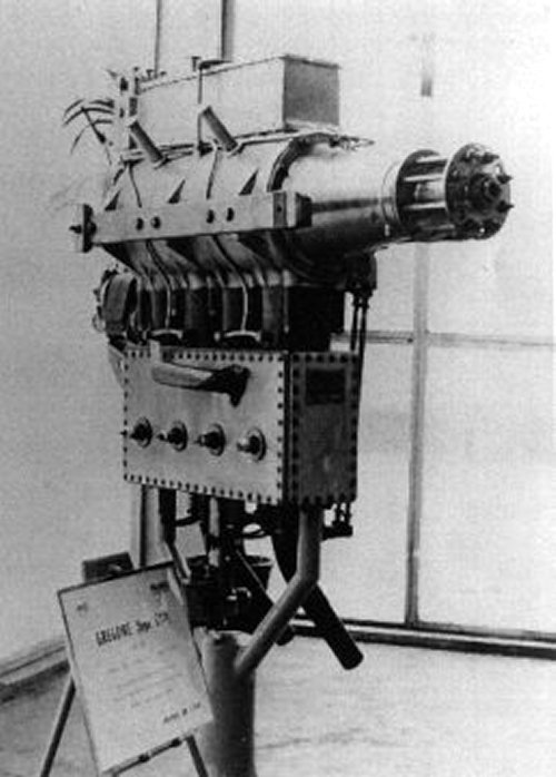 |
| Left: Gregoire engine: 1911
Here the engine is seen inverted, at an exhibition which was presumably the second Air Show in the Grand Palais, Paris.
The engine had its four cylinders cast in one block. The crankshaft had a single central bearing. It appears the water-jacket was actually fixed with screws, rather than rivets. But why? Other engines did not use this expensive approach. Could it be that the water jacket was under pressure, because an early pressurised cooling system was used? There is no actual evidence for this so far.
Both inlet and exhaust valves were mechanically operated. (ie there was no 'automatic' spring-loaded inlet valve)
The engine was available in three sizes:
- 1) Power 20/28 HP at 1700 rpm. Weight 60 kg
- 2) Power 30/40 HP at 1600 rpm. Weight 80 kg
- 3) Power 50/60 HP at 1300 rpm. Weight 11 kg; Clearly a misprint for 110 kg.
It is not known why two alternate power outputs were claimed; it may have depended on the exact type of fuel used.
|
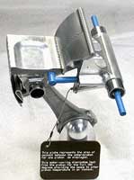
THE POLIZZI FLAP ENGINE: 1929
 |
| Left: The Polizzi flap engine: 1929
Originator: Paul Polizzi, USA
Quite what benefit Mr Polizzi hoped to gain from this ludicrous arrangement is unclear. There would have been the usual sealing problems at the end and sides of the flap, plus extra difficulties sealing the pivot point at 12.
Info from Patent 62251
|
THE PIVOTAL ENGINE: 2008
Having been rather rude about the the engine above, it came as rather a shock to find that there is a flapper engine under serious development today. Run, don't walk, to The Pivotal Engineering website. (Thanks to Jones The Engine for bringing this to my attention)
 |
| Left: Two, three and four chamber Pivotal engines.
These engines are assembled from modules.
Info from Pivotal Engineering website
|
  |
| Left: Two views of the water-cooled flap piston.
Info from Pivotal Engineering website
|
I only know what is posted on their website, but it does look as if they know what they're doing. They claim that their engine can have its combustion space thermally controlled, with no hot-spots, and that makes it especially suitable to run on hydrogen. Trying to run a normal IC engine on hydrogen results in catastrophic pre-ignition because hydrogen has such a low ignition temperature.
THE BAKEWELL WINGFOOT AERO ENGINE: 1939
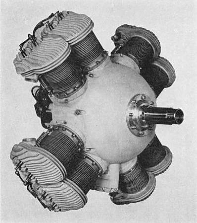 |
| Left: The Bakewell engine front view: 1939.
The Bakewell engine looks at first like an ordinary radial, but it was nothing of the kind. It consisted of four 90-degree V-twin engines, each with its own crankshaft, which was then geared to a common central propellor shaft. Propellor reduction gearing was fitted, the standard ratio being 1.57 to 1. This form of construction was claimed by the makers to give "inherent balance".
The eight cylinders had a bore of 4in and a stroke of 4.5in, giving a displacement of 452 in3. (7407 cc) Output was claimed as 165 HP at 2800 rpm. The compression ratio was 5.4 to 1.
The idea of multiple V-engines had already appeared in 1909 in the Breton engine, shown above.
From Aerosphere 1939.
|
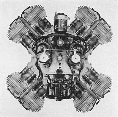 |
| Left: The Bakewell engine rear view: 1939.
Fear me, earthling! The Bakewell engine was built by the Shaw-Palmer-Bakewell Co of Los Angeles. Why it was called "Wingfoot" is currently obscure.
Because of the 90-degree V angle, the cylinders nestling together in fact belonged to different V-twins.
At least one of these engines has been preserved; see below...
From Aerosphere 1939
|
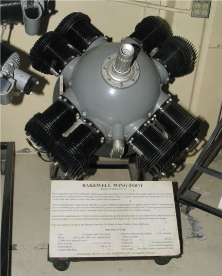 |
| Left: Bakewell Wingfoot engine on display
This engine is on display at the San Diego Air and Space Museum.
The crankshafts are of three piece construction. The cylinder barrels are nitralloy steel with the bore hardened. The rocker arms being enclosed in the crankcase are continually lubricated.
The valves are operated with a single cam for each cylinder, each cam shaft being mounted on two ball bearings.
Each crankshaft is mounted on three ball bearings and the propeller shaft, running straight through the motor, is also mounted on three ball bearings.
All oil lines are cast integral with the gear case sections and the oiling system is operated with two hardened gear pumps; one scavenge pump removing the oil from the sump and replacing it in the supply tank, the second taking its supply from the tank and forcing it into the propeller shaft; from which the oil is distributed by a force fed splash system.
|
THE JAMES ENGINE: 1963
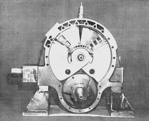 |
| Left: The James engine: 1963.
This engine was put forward by Richard James Cylindrical Motors Ltd. It was a two-stroke engine with two swivelling opposed pistons operating on a single crankshaft at the bottom of the housing, and employing uniflow scavenging. It was based on work started as long ago as 1929. This is believed to be a picture of the prototype, which may well have been the only one made.
An friend of Alan Lea (who has kindly provided the report on which this article is partly based) said: "he'd seen one in Vancouver in the early 70's. He said he'd seen it running on an office desk with a (exhaust ) pipe stuck out of the window. No vibration or apparent unbalance."
The James engine apparently got some support from the Canadian Federal Government, but what happened after that is currently unknown.
Info from Setright
|
 |
| Left: The James engine: 1963.
The internals of the James engine.
The prototype engine had a swept volume of 29.2 in3 (478.5 cc) and a compression ratio of 11:1. The pistons were 2.375 by 2.750 in, at the rectangular section, and had a 2-inch stroke. (measured at the outer radius?) The engine body was of aluminium alloy with a cast-iron cylinder liner. The water jacket was cast integrally with the main block. The connecting rods were of drop-forged H-section steel, the big end having a single-row roller bearing; the small-end bearing were of the needle-roller type.
The pistons were sealed by L-shaped piston "rings" of cast-iron, pressed against the cylinder walls by spring expanders.
From report An Evaluation Of James Hemispherical Opposed Piston Engine by John J Szendrey Dipl. Ing., 17 March 1967. (Very kindly provided by Alan Lea)
|
|
|
| Left: The James engine animated. Click on buttons to start/stop.
The fuel/air inlet is at extreme right. The transfer port is visible behind the right piston.
Another fine animation by Bill Todd. Javascript must be enabled for buttons to work.
|
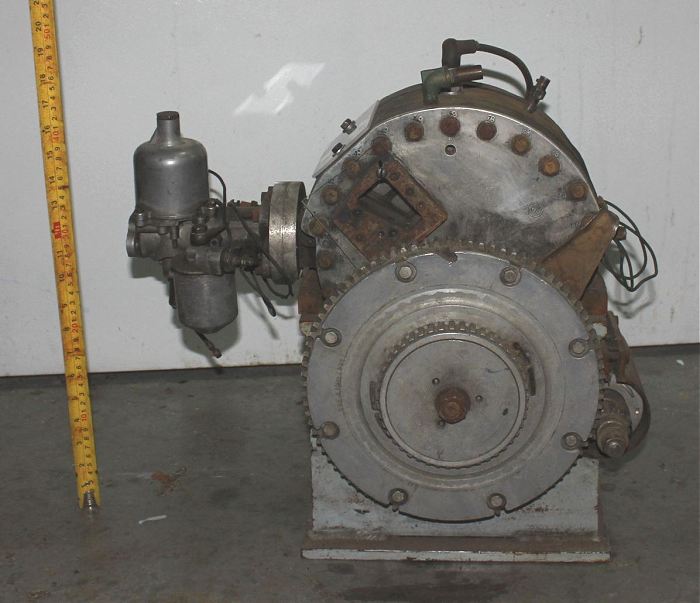 |
| Left: A James engine
This is claimed to be a 30 HP James engine. Dimensions are approx 12" wide, 14" high and 6" deep.
It is mounted on a simple flanged stand.
This picture of a real James engine was sent to me by a correspondent; at the time he was hoping to sell it. It was given to him by John Szendrey, a mechanical engineer who worked on the engine at a Government research center in Vancouver sometime in the 1970�s. I am told James sold his patent to Peel industries, and John Szendrey got the engine working and was named by James as co-inventor. Note the mention of his name above.
|
 |
| Left: A James engine: other side
The cylindrical thing on the lower left is the starter motor.
|
THE CHATER-LEA FACE-CAM ENGINE: 1926
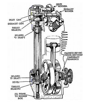 |
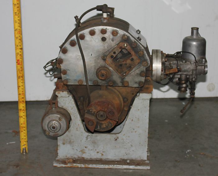
| Left: The Chater Lea face-cam engine: 1926
Chater Lea was a respected London-based firm which supplied frame fittings to bicycle and motorcycle makers, but also manufactured complete motorcycles. The single-cylinder 350cc face-cam engine appears to have been designed by Arthur Goodman and development engineer Dougal Marchant.
A vertical shaft driven off the crankshaft by bevel gears turned a pair of face cams, one above the other. The upper cam operate the inlet valve, and the lower cam the exhaust valve. A worm pump at the bottom of the vertical shaft fed oil up the hollow shaft centre to lubricate the cams; a separate pump supplied the crankshaft bearings and roller-bearing big-end. Note the spline connections to the shaft, presumably to allow for thermal expansion.
The possibility of desmodromic operation, (ie using the cams to positively close as well as open the valves, so valve springs could be dispensed with) was considered, but not adopted because it was felt that the mechanical clearances required for successful operation would be too critical for a non-technical owner to cope with. You did your own maintenance in those days.
The original source of this drawing is unknown, but from its style, was probably Motorcycling magazine.
|
Production ran from 1926 to the early 1930's, and approximately 550 face-cam models were made; this seems to demonstrate that it was a sound design. At least one example survives at The National Motorcycle Museum in Solihull.
THE DONOVAN FACE-CAM ENGINE: 1930
This single-cylinder engine was designed by the motorcycle racing rider and manager Don O'Donovan, for Raleigh, who then made motorcycles as well as bicycles.
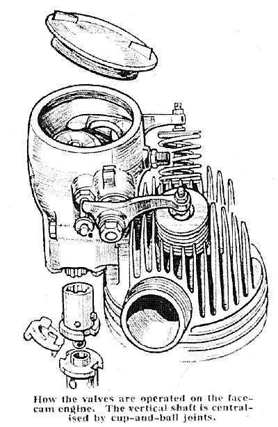 |
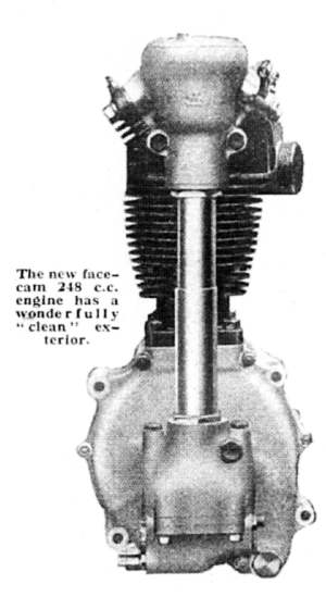
| Left: The O'Donovan face-cam engine: 1930
The induction and exhaust valves were actuated by tappets bearing on a single horizontal face-cam. The vertical shaft to the face-cam was driven by bevel-gearing from the crankshaft.
The arrangement is very similar to the Chater-Lea engine described just above. According to Bird, O'Donovan "would have had ample opportunity to study it". Enough said, I think.
The O'Donovan engine was never actually used on a Raleigh but was sold to Dunelt who used it in one of their models.
There is unfortunately a terrible snag in this very neat and compact arrangement. Since the same cam is used for induction and exhaust valves, there is no opportunity for optimising perormance by having different event timing for the two valves. I Am Not A Motorcycle Engine Designer, but I would have thought this introduced crippling limitations. (The Chater Lea engine had a separate face-cam for each valve, and so did not suffer from this problem)
The original source of this drawing is unknown, but from its style probably Motorcycling magazine.
Info from "A Glimpse of the Vintage Years of Motorcycling at Brooklands" by Roger Bird. (self-published in 2008)
|
 |
| Left: The O'Donovan face-cam engine: 1930
Note the telescopic tube around the valve driveshaft, to allow for thermal expansion of the cylinder. The oil pump can be seen underneath the bevel box, exactly where it was placed on the Chater-Lea engine.
|
 |
| Left: Don O'Donovan contemplates valve-timings
He appears to have reached some unhappy conclusions.
|
THE HEWITT PISTON-VALVE ENGINE: 1908
The poppet valve has been the dominant valve technology for most of the history of the internal-combustion engine.
Other serious contenders have been the sleeve-valve and the rotary valve.
However, the piston valve, so popular in steam engines, has always been a rarity, no doubt for good reasons. Here is an example that was patented in 1908 by James Mitchell Hewitt of Manchester.
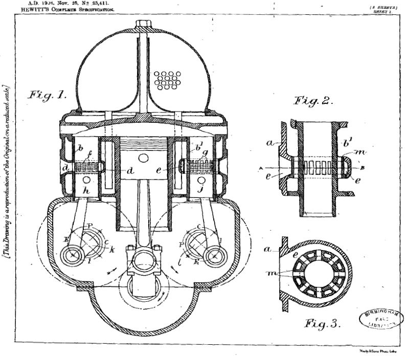 |
| Left: The Hewitt piston-valve engine: 1908
In Figure 1 the inlet valve h is on the left and the exhaust valve j on the right; both are driven by half-speed shafts geared to the crankshaft. The exhaust valve has water-cooling passages built in, as shown in Figures 2 and 3, and this is likely to be very necessary. The piston valves and main piston communicate with a large flattened combustion chamber. While I am not an IC engineer, I feel fairly confident in saying that this will give poor combustion and increased NOX output. I would be happy to hear from anyone with firmer information on this point.
The patent makes the intriguing point that the piston valves are not just valves; due to their piston action, with suitable timing they can help compress the charge and also will develop power on the expansion stroke. Whether this is either practical or useful I am not sure.
The big round thing on top is a mystery. It is not labelled in the drawings and is not mentioned in the patent. It may be something to do with the water cooling arrangements.
Apart from the patent, James Hewitt is unknown to Google, and I conclude the engine did not prosper, and was probably never built. The engine has nothing to do with the Hewitt Motor Company, founded in the USA in 1905 by Edward Ringwood Hewitt.
Image from British patent 25,411.
Application 25 Nov 1908, granted 25 Nov 1909.
|
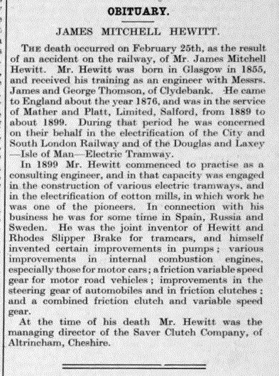 |
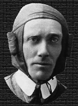
| Left: Hewitt obituary: 1918
James Hewitt may be unknown to Google, but not to Graces Guide. Here is his obituary.
I would like to know more about that railway accident. The Wikipedia list of British railway accidents has nothing for February 1918, and I fear that this might be the sort of accident where one person walks under a train. The Saver Clutch Company is also unknown to Google and this suggests it was not a great success.
The commercial success or otherwise of the Hewitt-Rhodes slipper brake is also currently unknown, but it can be said that US patent 714,798 was granted for it on the 2nd of December 1902.
From The Engineer for 8th March 1918
|
The fate of James Hewitt has now been established by Jonathan Fowler:
'To-day the body was found on the Midland Railway, near Matlock, of Mr. James Mitchell Hewitt, consulting engineer, of Hale, Cheshire. Deceased, who was about 60. had in his possession a ticket from Manchester to London. He apparently fell from an express last night.'
I fear Mr Hewitt may not have fallen accidentally.