Cam engines do not have conventional connecting rods and cranks, but instead rollers bearing upon cams to convert the piston thrust into rotation. This gallery only shows engines that have this cam mechanism as their main unusual feature.
Other cam engines, such as The Sparost Cam Engine of 193? or the The Dynacam Engine of 1941 can be found on The Axial engine page. The Dynacam engine is currently the last cam engine known to have been actually built, as opposed to just patented.
No IC cam engines have achieved any sustained success so far.

THE DANIEL CAM ENGINE: 1902
 |
| Left: The Daniel cam engine patent: US 817,905 of 17th April 1906.
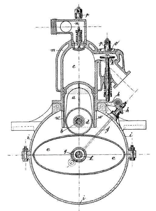
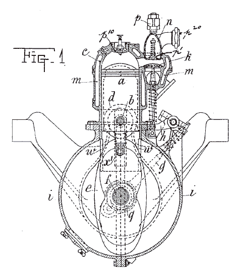
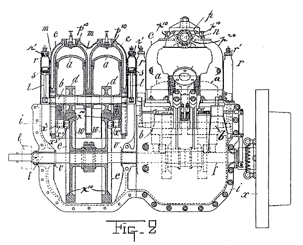
This is now the earliest cam-engine design known. The piston a with its roller d goes up and down on the elliptical cam e, being kept in contact with it by helical springs. (not shown here) There is an automatic inlet valve at n (common for the period) and a mechanically operated exhaust valve at k.
It is not known if this engine was ever built.
Source: French patent No 318251, Jan 1902
|
 |
| Left: The Daniel cam engine patent: US 817,905 of 17th April 1906.
This shows how the pistons went up and down in pairs; (not good for dynamic balance) each pair had two helical springs to keep the piston in contact with the cam. I would have thought that metal fatigue in the springs might be a problem.
Source: French patent No 318251, Jan 1902
|
THE DANIEL CAM ENGINE: 1906
 |
| Left: The Daniel cam engine patent: US 817,905 of 17th April 1906.
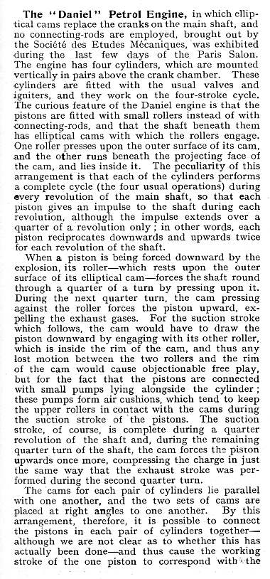
This French engine by Paul Daniel of Levallois-Perret, near Paris, was the subject of quite a comprehensive description in Model Engineer & Electrician for 28th April 1904. It is described as having been exhibited in "the last few days of the Paris salon", which possibly refers to the Exposition Universelle of 1900 in Paris, though that it would seem to indicate a pretty serious delay in reporting the fact. Perhaps some other exhibition is meant.
The report did not say if the engine was running; probably not in an exhibition hall. But it does appear to have been built.
There is a big roller d built into the bottom of the piston a which pushes on the top of the big elliptical cam e, and a little roller x' which bears on the inside of the cam. There is an automatic inlet valve p', and an exhaust valve k operated by rocking lever h, which is driven by an eccentric on the main output shaft; since this went round once per cycle, due to the bi-lobed nature of the cams, there was no need for a separate cam-shaft running at half engine speed. The patent claims this saves money.
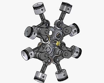
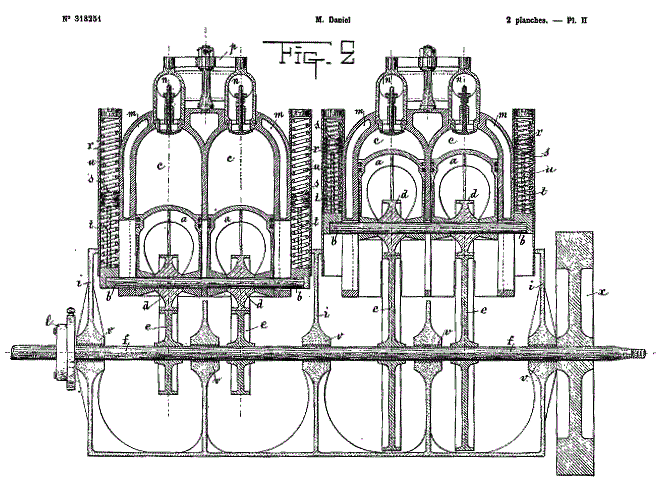
The Daniel engine was a water-cooled four-stroke, the cam system allowing it to complete one cycle for each revolution of the output shaft. The patent shows a four-cylinder engine with two groups of cylinders and cams, and air-spring cylinders to take up the backlash in the cam system.
From US Patent 817,905 of 17th April 1906
|
 |
| Left: The Daniel cam engine patent; side elevation
The small vertical cylinders r have an automatic valve r' at the top. This allows air to be drawn in and compressed on the upward stroke, acting as a pneumatic buffer. This enigmatic arrangement is said in the patent text to 'obviate the inconvenience which will arise from a failure of ignition, a non explosion, or the breakage of a valve.' This seems sinister: what the buffers actually do is not disclosed in the patent, and no other IC engines need them. They would add significantly to the cost of the engine, so they must be essential.
I suspected that something bad (but undescribed) happened in the cam system if the engine misses an explosion, and the buffers somehow guard against this by maintaining a downward force. This is confimed by the Model Engineer & Electrician article below; the buffers ensure that even if there is play between the cam and the two rollers, there will be a downward force to prevent the rollers banging about at each piston reversal. One suspects that the need for this was discovered the hard way.
Lubrication is by the splash method, the bottoms of the cams dipping into oil in the sump.
Note the four cylinders are in two pairs.
From US Patent 817,905 of 17th April 1906
|
  |
| Left: The Daniel cam engine as described in Model Engineer & Electrician for 28th April 1904.
|
 |
| Left: The Daniel cam engine in action.
Note how the thickness of the cam rim has to vary as the angle it makes with the cam rollers alters.
Another fine animation by Bill Todd
|
Intriguingly, searching 'Daniel Cam Engine' brings up a number of modern-day references; at least two modern papers have been written by Viorel Badescu. See also
here
THE GERMAN MICHEL CAM ENGINE: 1921
This cam engine has no connection beyond a coincidence of names with The Michell swashplate engine of 1920, which worked on a completely different principle. I have referred to this one throughout as The German Michel Cam Engine to underline the point.
The original documentation and the drawings are unfortunately neither as clear as they might be.
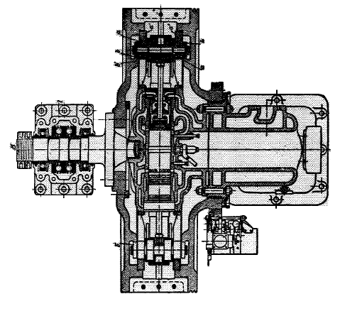 |
| Left: The German Michel Cam Engine: 1921
This engine was produced by the Michel Engine Company of Kiel, in Germany. It was a water-cooled two-stroke Diesel with three radial cylinders 120 degrees apart. The three cylinders shared a commmon central star-shaped combustion chamber, with the cam on the outside of the cylinders. The NACA report says the three cylinders revolved along with the fuel injection pump, while the cams and housing stayed stationary, but a look at the Michel patent shows the cam rotating around the outside.
To quote from the NACA report: "The introduction of fuel, lubricating oil, and cooling water into the revolving cylinders is said to cause no difficulty." Oh really? Was there a version where the cylinders did rotate? Confusing.
From NACA technical memorandum No 462, translation of Motorwagen Nov 20, 1927
Original source: Zeitschrift Des Vereines Deutscher Ingenieure (The magazine of the Association of German Engineers) p1405, 1925
|
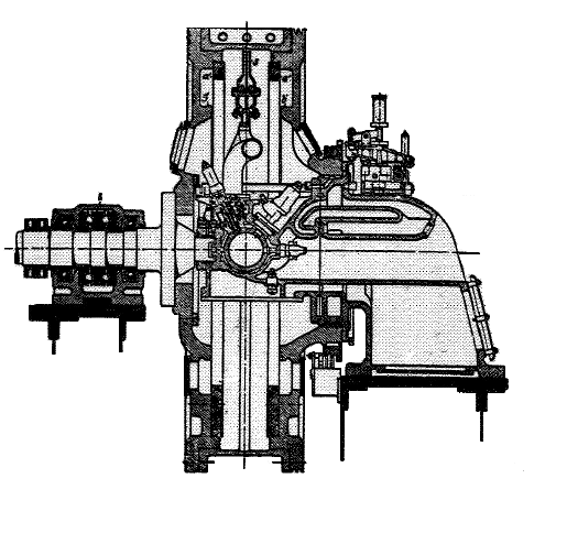 |
| Left: The German Michel Cam Engine: 1921
To quote from the NACA report again: "The cam shape is so constructed that the pistons execute four or six working cycles per revolution of the star-shaped
cylinder, thus automatically reducing the engine speed, (for
example), from 660 to 110 rpm, which is of considerable importance in marine installations. In spite of this, a proposed Michel engine of 1000 HP with a propeller shaft speed of 120 rpm, weighs about 42,000 kg, as against 128,000 kg for a four-stroke-cycle Diesel engine of 1000 IHP at 135 rpm; that is, the Michel engine with 50 to 60 kg/HP, is nearly twice as heavy as a submarine Diesel engine which weighs 25 to 30 kg/HP at 350 to 450 revolutions per minute."
The above doesn't much sense unless you assume that the two weights have been swopped by the original author, or more plausibly, that an unwanted 1 has crept in front of 28,000 kg.
"Whether the poor accessibility of the inclosed Michel engine with its revolving fuel pumps and nozzles; will give any
trouble in an endurance test , and whether (especially in the case of the large units of the Michel engine) it is off-set by
the saving in volume and weight, is still to be proved. In the recently built engines the roller bearings in the crossheads are
said to be replaced by plain bearings, evidently due to difficulties with the rollers."
From NACA technical memorandum No 462, translation of Motorwagen Nov 20, 1927
Original source: Zeitschrift Des Vereines Deutscher Ingenieure (The magazine of the Association of German Engineers) p1405, 1925
|
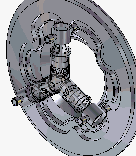 |
| Left: The Michel Cam Engine animated
If you find the drawings less than clear (and they seem to have defeated the the original author of the document) this should make all plain.
Animation by Bill Todd; another gem.
|
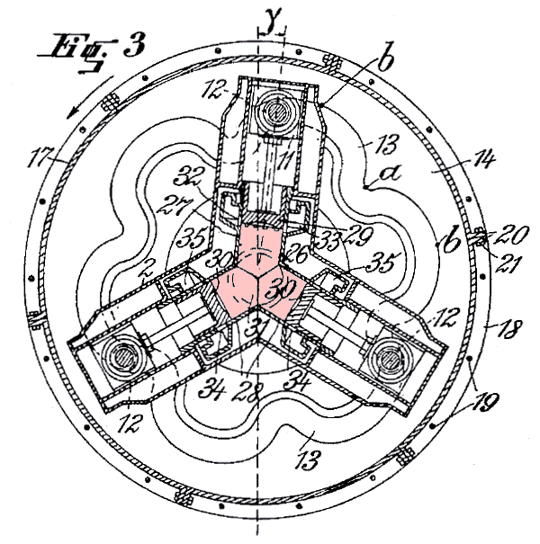 |
| Left: The Michel Cam Engine patent: 1921
The inlet ports in the lower two cylinders carry scavenging air into the combustion chamber. The upper cylinder has the exhaust ports. The
exhaust cylinder is canted over a few degrees in advance of the inlet cylinders, (the angle shown as gamma) to allow the exhaust port to open before the inlet ports (to
decompress the combustion chamber prior to scavenging) and to allow
the inlets to close after the exhaust. (to allow a small amount of super-charging)
The combustion chamber is here coloured a tasteful shade of pink.
From the Michel patent of 1921 (No 1,603,969)
Text by Bill Todd
|
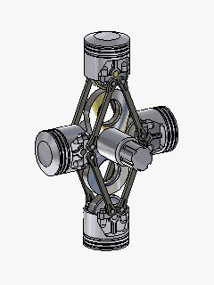
THE FAIRCHILD-CAMINEZ CAM ENGINE: 1926
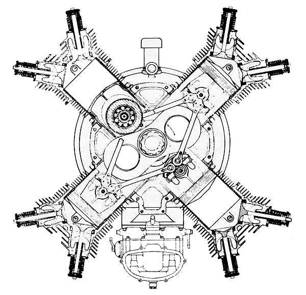 |
| Left: The Fairchild-Caminez Cam Engine: 1926.
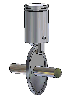
The Fairchild-Caminez 447 engine was a four-cylinder air-cooled radial intended for aircraft useage. It was designed by Harold Caminez, who had previously worked in the Engine Design Section of the US Army Air Service. The pistons acted on a leminiscate-shape cam, which made only one revolution for every two piston cycles, so for the same number of power impulses the engine ran at half speed. The pistons were connected by steel links to keep them pressed against the cam; the cylinder were steel with aluminium heads.
The Fairchild-Caminez 447 was first flown in an Avro 504 from Farmdale, Long Island, New York, in 1926. It was successfully endurance-tested in 1927, and was the first ever cam engine to receive a US Dept of commerce type certificate.
|
An IC engine expert speaks:
"Flight tests revealed what should have been predicted: a very large fourth-order torque variation due to the unusually heavy piston assemblies with their large ball-bearing rollers. Since the cam had two lobes, the second-order inertia torque of the conventional 4-cylnder engine becomes fourth order in the arrangement in question. The engine was abandoned on this account."
(Quote from The Internal-Combustion Engine in Theory and Practice by Charles Fayette Taylor, 2nd edition, pub MIT press 1985, p579. This is a standard work on IC engines)
It was indeed abandoned due to vibration problems in 1929.
Stroke:115 mm
Bore:143 mm
Capacity:7.3 litres
Compression ratio:5.2
Power:150HP at 2400 rpm
Flying weight:164 kg (1.1kg/HP)
Output/volume:20.5 HP/litre
| | | | | | | | | | | | | |
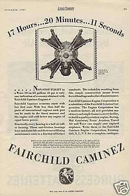 | |  |
| Far left: Advert for the Fairchild-Caminez Engine
Left: The Fairchild-Caminez Engine animated.
Another fine animation by Bill Todd
|
Data on the Fairchild-Caminez engine mostly from NACA technical memorandum No 462, translation of Motorwagen Nov 20, 1927:
original source was Zeitschrift Des Vereines Deutscher Ingenieure (The magazine of the Association of German Engineers) p1405, 1925
THE MARCHETTI CAM ENGINE: 1927
Paul J. Marchetti (1889-1929) was born in Italy. In 1922 he was working on a radial four-lobed cam engine with Henry A. Nordwick in Stockton, California. A patent for this was filed in 1922. Further patents were filed in 1923 and 1924, and again in 1926.
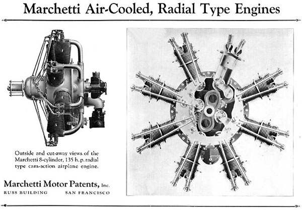 |
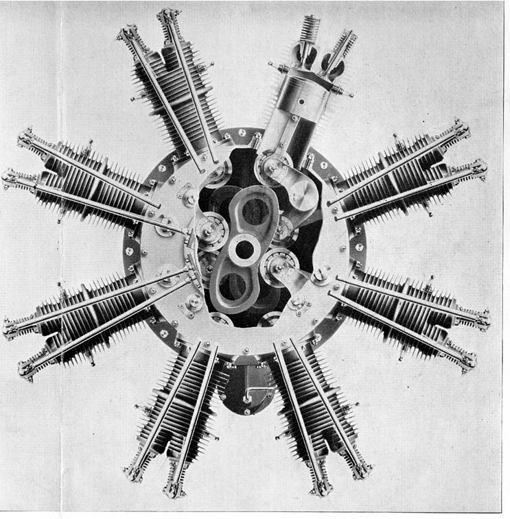
| Left: The Marchetti Cam Engine
This 8-cylinder radial cam engine had two cams 45 degrees out of phase, both driving rocker arms that could pull and push on each piston. There were two cam rings, one front and another back, each driving the valves for four cylinders.
But surely a radial engine has to have an odd number of cylinders to get even firing angles? Not in this case. As Bill Todd points out: "A cam engine fires every 360 degrees, so a two, four or eight will give 180, 90 or 45 degrees between firings and can be evenly spaced in a circle."
Only one prototype was made, for Paul Marchetti of Marchetti Motor Patents Inc, Mills Field, San Bruno, Calif. Marchetti took out US patent 1,654,378 for cam engines in December 1927. It does not show the engine in the form it appears here.
|
It appears that a highly modified Cessna AW with monocoque fuselage and lengthened wings was built to accept the prototype engine, but Paul Marchetti was killed in a crash during flight training. Keith Rider, who had been one of Marchetti's employees, acquired the company in 1930, and then sold the property and assets to United States Aircraft Ltd. of San Francisco, later in the same year.
|
|
| Left: The Marchetti Cam Engine animated! Click on buttons to start/stop.
Note that the bell-crank cam followers are pivoted on arms that move the pivot point inwards.
Animation by Bill Todd, who's come up with a beauty here. Javascript must be enabled for the start/stop buttons to work.
|
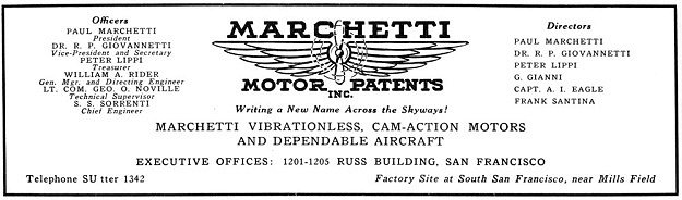 |
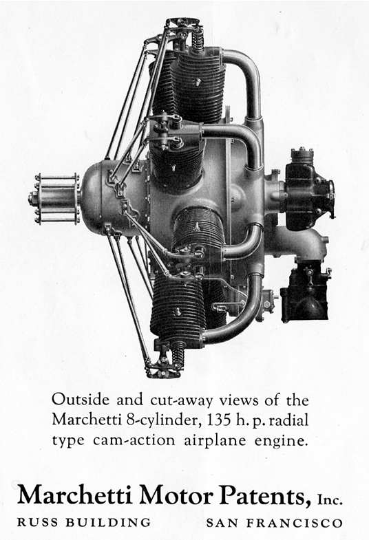
| Left: The Marchetti Cam Engine: 1929
This is a Marchetti Motor Patents Inc. advertisement from 1929.
Marchetti had ambitions to be a pilot. On 31st August 1929, one week before the manufacturing plant opened, Marchetti took off from Mills Field to overfly the almost-finished factory, and to log some flying time towards the two hours remaining to qualify for his pilot�s license. He flew into a fog bank, and apparently became disoriented, not having training in instrument flying. The plane emerged from the fog bank in an inverted flat spin, and crashed half a mile out into the San Francisco Bay. Marchetti was killed, and that was the end of the business.
|
 |
| Left: The Marchetti Cam Engine: 1929
A better version of the picture above.
|
 |
| Left: The Marchetti Cam Engine: 1929
Again, a better version of the picture above.
There are some more details, and another animation here.
|
So far,this seems to be last-but-one cam engine that was actually built; the last possibly being the <>Dyna-cam engine<> of 1941.
THE WOOLSON CAM ENGINE PATENT: 1931
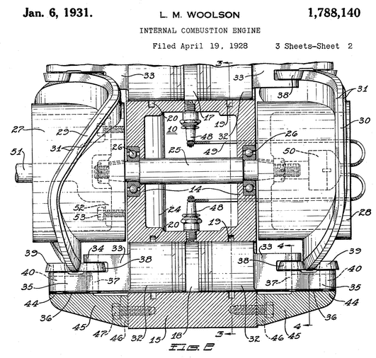 |
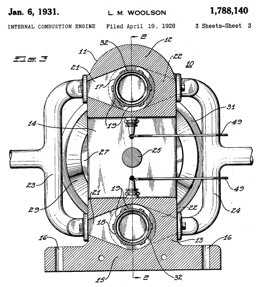
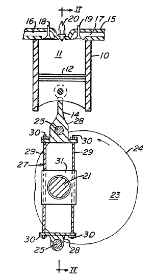
| Left: The Woolson Cam Engine patent, side view: 1931
The Woolson engine design had opposed pistons bearing on a circular cam track. It was supposed to work on a five-stroke cycle, with one being an 'idle stroke'. It was intended to be water-cooled. Woolson claimed as its advantages positive valve action, �extreme simplicity of construction,� and elimination of side-thrust on the pistons, which occurs with a conventional crank.
Note the pair of bevelled wheels attached to each piston.
Captain Lionel M Woolson was employed by Packard to design conventional engines, many of them for aircraft use. This cam-engine appears to be his only excursion into the unconventional. The patent was originally filed in April 1928. There is no evidence the engine was ever built.
Woolson died in a plane crash in April 1930 at the age of 41. There is more information about him here.
Source: US patent 1,788,140 issued Jan 1931.
|
 |
| Left: The Woolson Cam Engine patent, end view: 1931
The Woolson engine, like many cam engines, had a lot of wasted space in the middle. Presumably this is because if the pistons were closer to each other, the angle of the cam(s) would become impracticable.
Source: US patent 1,788,140 issued Jan 1931.
|
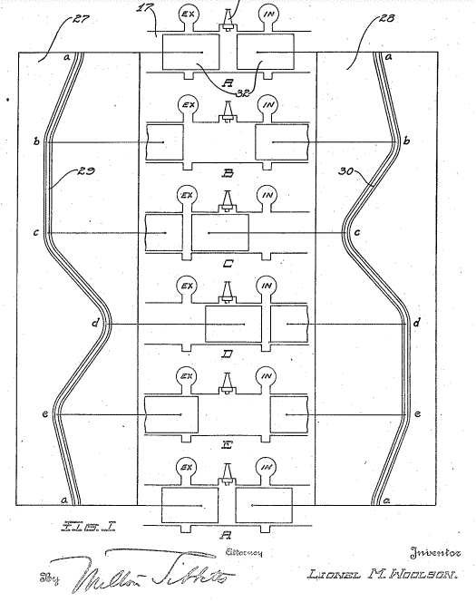 |
| Left: The Woolson Cam Engine patent, end view: 1931
This shows the complex profiles of the two cams. The vertical sections, where the adjacent piston does not move, presumably implement the 'idle strokes'. The intended purpose of such strokes may be buried somewhere in the text of the patent, but I have not gone through it all yet.
Source: US patent 1,788,140 issued Jan 1931.
|
THE FLEMING CAM ENGINE PATENT: 1981
 |
| Left: The Fleming Cam Engine Patent: 1981
Here the connecting rod 14 has two rollers 25 that bear on the big cam 24. These rollers are a fixed distance apart, which I would have thought placed some severe restrictions on the shape of the cam. (The patent contains a lot of mathematics on the shape of the cam) The piece 31, which the connecting rod slides through, is pivoted on the output shaft 21.
It is not clear from a first reading of the patent just what was being aimed at here; there is no mention of three-cycle or any other unusual sort of operation. The Fleming cam engine is unknown to Google, and it is unlikely a prototype was built.
Source: US patent 4,301,776 of Nov 1981
|
THE FISHER CAM ENGINE PATENT: 1983
 |
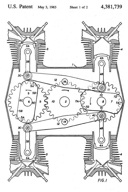
| Left: The Fisher Cam Engine Patent: 1981
This patent claims to have improved on the conventional crankshaft; the author is convinced his arrangement "is superior and will replace the conventional crankshaft, other possible cam engines, and the gas turbine." which if nothing else shows confidence in the concept. Other objects were: "...better fuel economy, less manufacturing cost, less repair and maintenance, less air pollution and a better vibrant balance." Sounds highly desirable, but...
We see here two opposed pistons 3 in a ported cylinder, moved in and out by two enormous levers 5, which have rollers 6 bearing on the cam 7, which is fixed to output shaft 8. Two other cams 12 are mounted on shafts 11 which are driven by gears from the output shaft; these cams press the levers 5 against the main cam 7. This all sounds a bit unlikely, but the patent text claims that an engine of this sort "... has been developed by the Svanemolle Wharf Co of Copenhagen, Denmark, for marine and stationary applications." This is said "not to have the improved features shown" as otherwise it would have invalidated the patent. Sadly the Svanemolle Wharf Company is unknown to Google. So is the Fisher engine, and it is therefore unlikely it was ever built.
The patent also refers to the Fairchild-Caminez Cam Engine.
One obvious objection is the enormous amount of space and weight taken up the cam mechanism. Also, if 4 is a rigid bearing then the lever 5 - piston 3 combination cannot move.
There is no mention of three-cycle or any other unusual sort of operation.
|
 |
| Left: The Fisher Cam Engine Patent: 1981
This is an alternative expression of the Fisher concept. (such as it was) Here there are four cylinders rather than two, and the cams and levers work quite differently. There are now explicit connecting rods 3B, so the pistons can at least move.
However the amount of space taken up compared with a conventional four-in-line crank engine is grotesque.
|
THE CROCKER CAM ENGINE PATENT: 1983
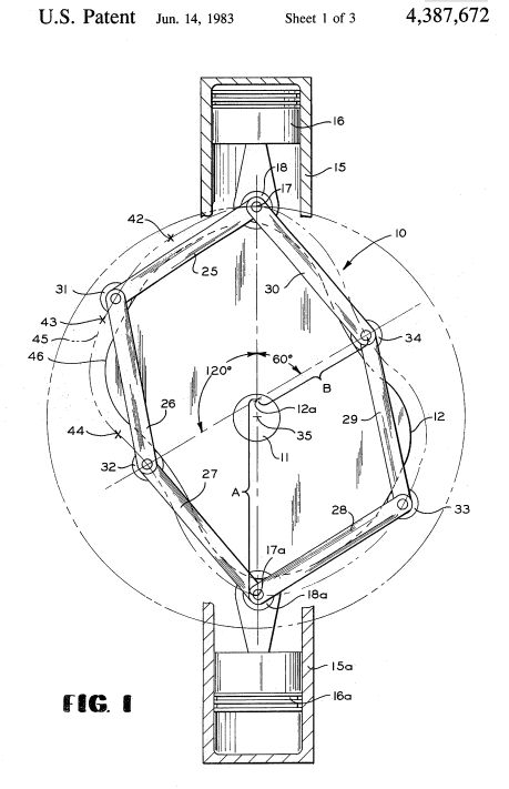 |
| Left: The Crocker Cam Engine Patent: 1983
The main purpose of this patent was to allow the power and induction phases of the four-cycle to be extended compared with the other phases and so improve efficiency. It was not an attempt at to make a three-cycle engine, although it was cited in Ward's Three-cycle patent.
Am obvious problem here is that the cam that allows cycle times to be set is much bigger and heavier than a conventional crankshaft.
Crocker's engine is wholly unknown to Google, and the assumption must be that no example was ever built.
Source: US Patent 4,387,672 June 1983
|
There is a Wikipedia page for cam engines: https://en.wikipedia.org/wiki/Cam_engine