Several inventors have persuaded thenselves that having curved pistons oscillating or rotating inside a cylinder block is a good idea. It is not.
An engine expert speaks:
"A great many ideas for engines in which toroidal pistons rotate or reciprocate within toroidal cylinders have been advanced. The difficulties of connecting such pistons to the output shaft by a simple and reliable mechanism, together with the problem of sealing the surfaces involved, make such ideas little more than amusing adventures in ingenuity."
Quote from The Internal-Combustion Engine in Theory and Practice by Charles Fayette Taylor, 2nd edition, pub MIT press 1985. This book is one of the standard works on the subject. Taylor was Professor of Automotive Engineering at MIT; he has little time for unconventional engines of any kind, and his arguments are persuasive.
Note that Wikipedia refers to this sort of configuration as a Swing-piston engine. Some new information was obtained from "Failed Motor Concepts- Improper Structures or Change Of Boundary Conditions?" by Prof. Dr. Ing. Stefan Zima.

HISTORICAL TOROIDAL ENGINES
THE DEWANDRE ENGINE: 1905
According to Karl Ludvigsen, Dewandre built a toroidal IC engine in France in 1905, that was revived as the Esselbe for aviation use in 1912. The country was probably actually Belgium.
The only information found so far is British patent 28,511 granted on 19th October 1911. It states that the first foreign patent (in Belgium) was applied for on 7th December 1909. Albert Dewandre is said to be living in Liege, Belgium.
 |
| Left: The Dewandre toroidal engine: 1910
The British patent explicitly states that this is a rotary engine, meaning that the engine rotates around a stationary central shaft. There are eight pistons fixed in pairs. There are no barriers
17:51 25/08/2011
between the pistons so this is an opposed-piston design.
Four spur gears 15, 16, 17, 18 engage with gear 24 on the central shaft, and reciprocate the piston assemblies via short connecting rods 10, 11, 12, 13.
Fig 2 shows how the fuel-air mixture is supplied through the hollow central shaft 25, is turned through 90 degrees by the elegantly-shaped spiky thing 35, and sent to the inlet valves via pipes 36.
From British patent 28,511
|
 |
| Left: The Dewandre toroidal engine: 1910
Fig 3 shows how the fuel-air mixture reaches the inlet valve 7, on the inner side of the toroid. The exahaust valve 32 is on the outer side of the toroid, the exhaust gases going directly from the valve port to the open air. The valves are operated by a cam 27 fixed to the central shaft.
Note that the fins on the toroid are arranged to lie in the direction of air flow as it rotates.
From British patent 28,511
|
The Dewandre engine is unknown to Google.
THE BECK ROTARY ENGINE: 1909-11
The Beck rotary toroidal engine went through various incarnations over a few years- a very short time for engine development. I have tried to identify these in the correct order and with the correct date.
 |
| Left: The first Beck toroidal engine: 1909
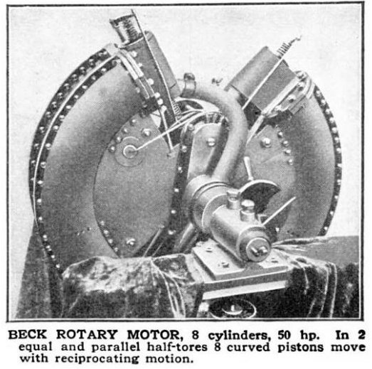
The initial Beck engine was a four-stroke spark-ignition design, with eight pistons moving in a single toroidal bore. It appears to have been exhibited at the Paris air show in 1909, where the British journal Flight described it thus:
"Dimensions: 80 mm by 180 mm, weight, 40 kilogs, 40 HP, price, 10,000 Francs."
The size is clearly far too small, and I suspect that some English journalist unfamiliar with the metric system got that wrong, perhaps by confusing mm with cm, though a diameter of 180 cm seems much too large- it would have been about six feet across. Not very plausible for a frail 1909 aircraft.
The Flight article described it as a rotary engine; in the context of aero-engines this means that the engine rotates around a stationary shaft and carries the propellor around with it. The cylinders are divided by four fixed partitions at A, so this is not an opposed-piston design. As the crank C rotates the associated levers cause the radial arms R to oscillate, carrying the pistons P with them.
The output is stated by Prof Zima as 66 kW (90 HP) at 1800rpm, though whether this was a design aim or actually achieved is uncertain.
|
Frederic Beck appears to have been Austrian, but like other inventors seems to have concluded his invention would do better in France. He lived in Neuilly-sur-Seine in France. By 1910 he seems to have rethought his engine, and obtained US patent 977,260 for a "rotary explosion motor" using bell cranks and a face cam to drive the pistons.
 |
| Left: Second version of the Beck toroidal engine patent: 1910
Note there are still barriers 16 between the pistons, so each one has its own combustion chamber. The bell-cranks 10 are shown in a tasteful shade of blue. The patent text makes it clear that this is a rotary engine in the aero-engine sense: in other words the engine rotates around a stationary centre. Here the cam-plate is stationary and the toroid rotates around it.
The shape of the cam track indicates that the bell-cranks and pistons would undergo some pretty vicious accelerations. This does not look very practical to me.
The valves are composed of sliding rings 17, 18 set into the barriers between the pistons. These cover and uncover rows of ports in the toroid.
It is not known if this engine was ever built.
From US patent 977,260
|
 |
| Left: Second version of the 1910 Beck toroidal engine patent animated
Bill Todd comments: "It's an interesting design- the cam plate, which is supposed to be fixed with the cylinder revolving around it, is completely enclosed in moving parts making it impossible to build! (according to the drawing)"
Note the little rollers (14,15 in the drawing above) that bear on the outside of the toroid. The text of the patent says "This device is intended to prevent the tendency of the pistons to deform the ring cylinder under the action of the centrifugal forces." which makes little sense to me unless the idea is to spread the centrifugal force out over more of the periphery.
In the animation the cylinder is held stationary while the cam-plate revolves as this gives a better view of the piston movements; since this is a rotary engine in actual use the cam-plate would remain stationary as the toroid revolved around it.
Another fine animation by Bill Todd, now showing the sliding valve-rings at the end of each 'cylinder'.
|
 |
| Left: Third version of Beck rotary engine 1911
This is the engine which was exhibited at the second Air Show in the Grand Palais in Paris, held in October 1910.
The rounded housings at the end of each toroid segment, one at each end, house the inlet and exhaust valves. These were driven from camshafts just above and below the crankshaft. No method of cooling is shown; presumably Beck was relying on the toroid segments whirling around in the airflow. Note that there are two pairs of toroid sections joined together, which is why the piston count is still eight and not reduced to four.
From Popular Mechanics for Jan 1911
|
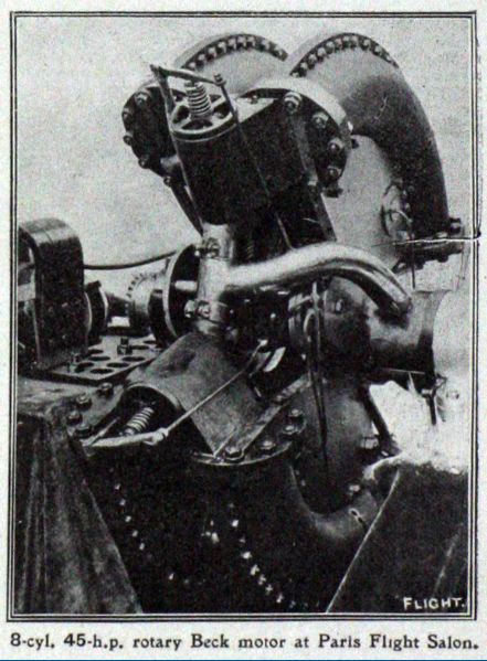 |
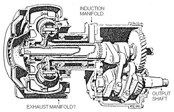
| Left: Third version of Beck rotary engine: 1911
The Beck Paris engine from a slightly different angle, showing how the toroid segments are mounted side-by-side. The curved pipe appears to be an induction manifold, fed from the carburettor via a hollow crankshaft, as was the usual practice in rotary engines. It looks as though the exhaust escapes through apertures around the exhaust valve; I doubt if that would do the valve-spring much good.
Image from Flight magazine, 1910
|
By 1913 Beck seems to have rethought his engine again, as Austrian patent 59916 shows a different drive-mechanism using bell-cranks, links, and twin quarter-segment toroids. I think this was the third design, shown at the second air show, as in the photographs above.
 |
| Left: Third version of Beck toroidal engine patent: 1913
Only half the toroid is present now. Each piston has a separate combustion chamber and valves. Once again the bell-cranks are shown in blue, and the connecting rods in green. The valves are driven from camshafts above and below the crankshaft, shown in orange. These were presumably driven by spur gears from the crankshaft.
The text of the patent is in German, and I have not had time to translate it, but it seems that this is still a rotary engine, ie engine rotates while centre shaft stays still. The arrow F at top left supports this view.
From Austrian patent 59166.
|
 |
| Left: Third version of Beck toroidal engine: 1913
There are two half-toroids side-by-side, presumably to give balanced loads on the driving mechanism.
Bell-cranks in blue, connecting rods in green.
From Austrian patent 59166.
|
THE ESSELBE ENGINE: 1912
 |
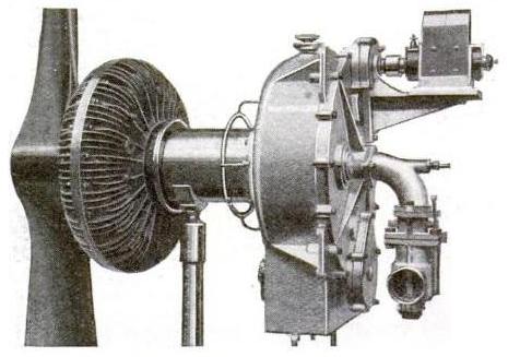
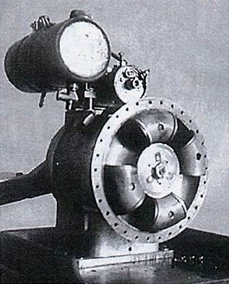
| Left: The Esselbe toroidal engine: 1912
This was a four-stroke spark-ignition engine, with a bore of 65 mm and a stroke 270 mm. According to Zima the output was 44 kW (60 HP) at 1200 rpm; the year of construction was 1912. It is a mystery why the engine is laid out with an enormous gap between the cylinders and the gear-case to the right. The Dewandre engine, (above) from which this engine is supposed to be derived, has no such spacing.
Top right is the ignition magneto, and bottom right the carburettor, which apparently feeds the cylinders via a hollow central shaft; the exhaust presumably exited straight out of the valve ports. The propellor shaft is sticking out to the left.
|
 |
| Left: The Esselbe engine layout (after Zima)
This diagram shows how four double-faced pistons were driven by four crankshafts, each geared to a central shaft. The rather heavy-looking gearing involved can be seen to the right of centre in the photograph above.
It occurs to me that the name Esselb� (= SLB?) might be the initials of those involved in the project.
According to Karl Ludvigsen this engine was a development of the Dewandre engine mentioned above.
|
 |
| Left: The Esselbe engine with prop and gear-casing in place
The Esselbe engine was also exhibited at the Paris air show in 1913; the US journal Popular Mechanics described it as "The Motor Feature of the show".
This picture gives a better idea of a major problem with this design; the gear-case looks bigger and heavier than the cylinder assembly. The box at the bottom of the gear-case is presumably the oil sump.
It doesn't look as if the fins on the rear of the cylinders would get much air.
|
THE GOUX-SAINT-GENIES ENGINE: 1917
 |
| Left: The Goux-Saint-Genies engine: 1917
One of my correspondents sent me this:
"While looking in the archives of Jules GOUX (1885-1965) Peugeot racing car driver, I found documents on a toroidal rotary engine studied and produced in 1917.The group included in addition to Jules Goux, Henri Jacques de Lassus de Saint Genies (chief engineer), Ponnier (aircraft manufacturer) and Lariboisi�re. The engine developed 50 HP on the dynometer. It does not appear that a patent was filed."
Getting a patent may have been impossible due to previous patents taken out by Beck several years earlier.
|
It seems likely this engine had a similar crank mechanism to the 1909 Beck engine (the first version of the Beck). I can't see any water jacket connections so I assume those corrugations are supposed to be cooling fins. Not very effective in that format, I'll wager. It is not known if the operation was two or four-stroke, but no valve mechanism is visible so two-stroke is more likely.
Jules Goux has a Wikipedia page, but it does not mention this engine. He was a graduate of Arts et Metiers, Paris, and so very likely also a competent engineer.
Henri Jacques de Lassus de Saint Genies is unknown to Google, but I did find Anne Henri Jacques de Lassus Saint Genies, (of Versailles, France) whom I think we can safely assume was his daughter. She took out at least two USA patents on photography. These were US 2,131,974 of Oct 1938, and US 2,230,938 of Feb 1941.
Ponnier were a less than sucessful aircraft manufacturer. Their L1 biplane never reached production, and their M1 biplane of which perhaps 18 were built, proved ineffective.
The name Lariboisi�re is obscure. It is the name of a hospital in Paris.
THE WOLFF ENGINE: 1929
According to Karl Ludvigsen "In Nebraska's Omaha engineer Louis Wolff built toroidal engines for both vehicles and aircraft during the 1930s. Strong claims for products of his Toroidal Aircraft Motors Company failed to translate into practice."
The Toroidal Aircraft Motors Company is unknown to Google.
 |
| Left: The Wolff engine: 1929
The engine consisted of a large rocking element (42) carrying four pistons. The section of toroid (25) was divided by barriers so that four separate cylinders were formed. The rocking element was connected to the crank (14) by a conventional connecting rod. (46)
It is difficult to see what the advantages of this engine might be. For one thing, it takes up a lot more frontal area than a conventional in-line 4-cylinder engine, and that increases aerodynamic drag, though it might help air-cooling. However perhaps a bigger worry is that there seems to be no attempt to balance that large and heavy rocking element. The small balance weight (16) on the crankshaft will only partially balance the connecting rod. (46)
One aim mentioned in the patent text is the reduction of piston-cylinder friction because there is no side-thrust on the cylinder walls. Friction in IC engines is not negligible but this does not seem like a good way to reduce it.
From US patent 1,809,577 of 9th June 1931.
|
THE PADDON ENGINE: 1930??
Yet again according to Karl Ludvigsen a man called John Paddon designed a toroidal engine in the 1930's, in which the pistons were controlled by cams. This engine is unknown to Google, and to the US Patent system.
THE BRADSHAW OMEGA ENGINE: 1955
 |
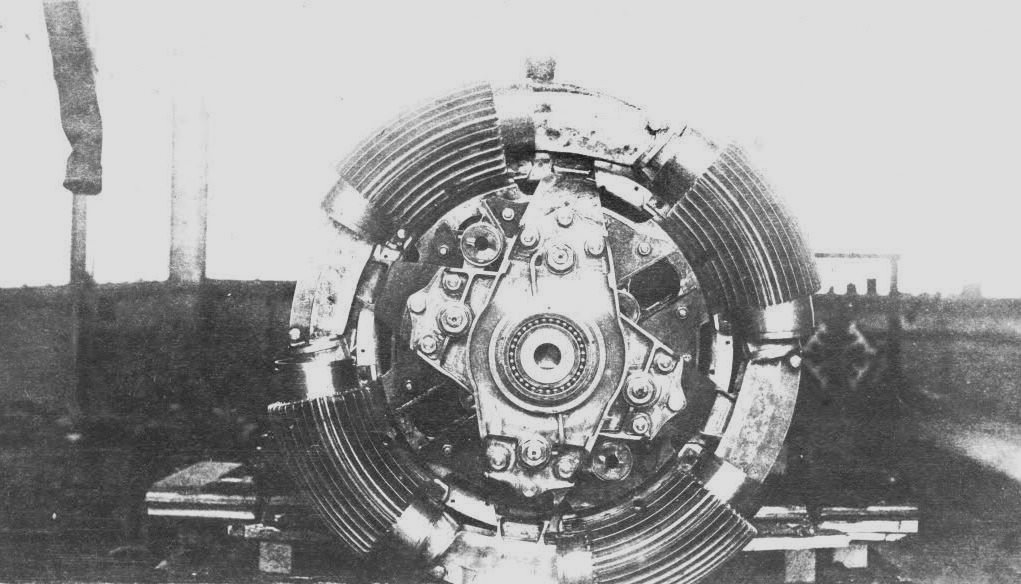
| Left: A prototype of the Bradshaw Omega toroidal engine: 1955
Originator: Granville Eastwood Bradshaw (1887�1969)
The Bradshaw engine had a single toroidal cylinder, containing four double-ended curved pistons. The pistons reciprocated in pairs, while the cylinder rotated around them, carrying around the spark plug and inlet/exhaust ports. The connection to that spark plug must have involved some complications- a slip-ring, perhaps, or maybe non-touching contacts like the inside of a distributor cap?
According to Karl Ludvigsen Bradshaw built both 1100 and 1250cc versions of his engine.
|
 |
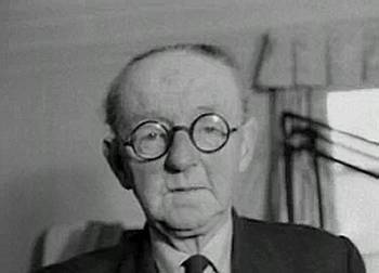
| Left: Granville Bradshaw
From Popular Science, date unknown.
Granville Bradshaw was no solitary eccentric; he was a respected engine designer who began his career in 1910 and designed the first Pratt & Whitney radial aircraft engine during World War 1. At the time of the Popular Science article he was 67, and described as a "millionaire inventor". He worked extensively on motorbike engines ; see www.realclassic.co.uk (external link) for an interesting motorcycle engine in which the cylinder is cooled by oil rather than air or water.
I have so far not discovered what advantages Bradshaw thought his engine had over more conventional designs. Its less-than-compact layout is one snag, and surely those section-of-a-toroid pistons must have been expensive to make?
|
 |
| Left: The Bradshaw Omega engine: 1955
Wouldn't that pair of single-helical gears generate end thrust? Perhaps not enough to worry about.
From Popular Science, June 1956.
|
 |
| Left: The Bradshaw Omega engine principle
The cylinder was rotated by the central shaft while the cranks that reciprocated the pistons were driven by the output shaft, running at half the cylinder speed.
From Popular Science, date unknown.
|
NEW You can see a five-minute film of Granville Bradshaw describing his ideas and his intention to make Britain a world-dominating motor manufacturer on the British Pathe site. I am grateful to Ken Gasmier for bringing this to my attention.
 |
| Left: Granville Bradshaw in 1955
A biography of Granville is now available: 'Granville Bradshaw: a flawed genius?' by Barry Jones. Looks well worth reading.
According to one commentator from the world of motorcycles:
"The Omega was the final fling of a man whose ideas were always clever and innovative, but who sadly failed to understand the commercial needs of the business. His designs were novel, but invariably costly and seldom trouble-free, so his long involvement with the industry made news and kept everyone intrigued, rather than producing machines for riding."
|
It appears his aeroplane engines were also problematic: see Wikipedia.
I unearthed this quote from Patrick Head, one of the great engineers of Grand Prix racing:
"They had a wonderful project while I was down at Harry Westlake's. Somebody had sent them an engine called a Bradshaw, and it arrived in a cardboard box. It was basically a toroidal chamber with pistons which filled a section of the toroid, attached to two crosses, such that, as they went round, gearing superimposed an oscillation on the rotary motion. Intakes, exhaust and spark plugs were arranged around the periphery of the chamber. I was asked to find out how this engine worked, assemble it and install it on a dynamometer so that it could be evaluated.
"There was no inlet manifold or carburettor, so I got an Amal and made an inlet manifold, assembled the whole contraption and put it on the dyno. It happened that Dan Gurney turned up on the day we were due to start it up, and watched from outside the dyno. room, behind the bullet-proof glass. Anyway, this Bradshaw engine started up - the guy had said that it was perfectly balanced and would rev to umpteen thousand RPM - the only problem was that in the gear casing, at the back of the engine, he had made all the gears himself, with a file or something! The pitch of the teeth were all irregular and I had to do an incredible amount of lapping - the quality of build was awful.
"Anyway it did start and run, and I fiddled about with the carburettor and sorted out a few things. Dan Gurney was outside and encouraging us to give it the berries. While it was idling at a few hundred RPM a cloud of smoke gradually built up in the dyno. room. Eventually we gave it some more RPM, only about 2,500, when suddenly there was a mighty BANG! and the whole of the glass window disappeared in a mess of oil and metal. Slowly the murk cleared and all we could see through the smoke were the feet of the gearcase, and the toroidal chamber, with bits of cast iron and aluminium all over the place.
"It all got collected up, put back in the box and sent back to Mr Bradshaw. I don't think his concept was properly evaluated at all....."
It is not clear from this description of an extraordinarily casual approach to engine testing what failed- perhaps the home-made gearwheels were not up to the job. At any rate, it is clear that it did run.
If Mr Bradshaw was paying to have his engine tested, I should think he was very angry indeed.
 |
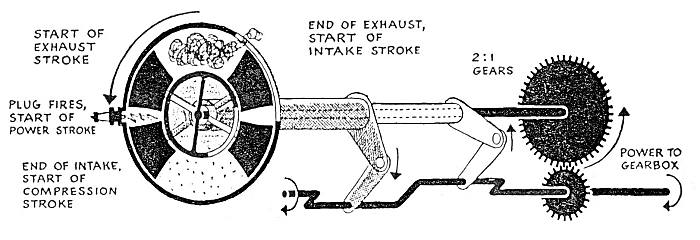
| Left: Animation of the Bradshaw Omega engine.
Note how the spark plug goes round with the toroid, passing the pistons as they come together at the end of the compression part of the cycle. The white comet-shaped thing going round is the exhaust port.
Another stunning animation by Bill Todd.
|
 |
| Left: Another pic of the Bradshaw Omega engine.
As in all toroidal engines, there have to be slots in the cylinder wall to couple with the piston, and these need to be sealed. How this was done in the Bradshaw engine is not known.
Source unknown, but from the style, probably Motorcycle magazine.
|
THE BSA TOROIDAL ENGINE: 1955
This toroidal two-stroke engine was designed by the British motorcycle company BSA, and was intended for powering mopeds or cyclemotors. Development began in late 1938, and since it was reported by The Motor Cycle in August 1955, appears to have proceeded very slowy, though no doubt the project was shelved during World War Two. The swept volume was only 34cc. It definitely ran, but by all accounts, a prototype produced little more than enough power to overcome its own friction and pumping losses.
 |
| Left: The BSA Toroidal engine: 1955.
There is an obvious resemblance to the Bradshaw Omega engine, but I have not so far found any reports that Bradshaw worked with BSA. The two halves of the rotating cylinder assembly were made in cast iron and was fitted with curved fins for cooling.
As in all toroidal engines, there have to be slots in the cylinder wall to couple with the piston, and these need to be sealed. How this was done in this engine is not known; possibly the slot was short enough so it stayed in the centre section between the two sets of rings on each piston.
From The Motor Cycle Aug 1955
|
Research has unearthed no other reference to this engine, and the assumption must be that development work was abandoned in 1955 or shortly after. I have never understood the thinking behind this apparently daft project. Surely a moped engine should be as simple and easy to manufacture as possible?
 |
| Left: The BSA Toroidal engine: the principle.
The mechanism is clearly different from the Bradshaw, but the exact operation is rather obscure.
According to The Motor Cycle: "Dividing the toroid are two partitions at 180 degrees; within each half is a long double-ended piston and two pistons are coupled by a diametrical arm."
If there are fixed partitions, then clearly the pistons must be going round with the cylinder block, as otherwise they would whack into them. This appears to be indicated by the arrow in the middle.
The functioning to the two pairs of gears to the left is also a bit mysterious, as one of the pairs seems to be redundant. If anyone knows anything more about this engine I would be glad to hear from them.
From The Motor Cycle Aug 1955
|
THE TSCHUDI ENGINE: 1967
Originator: Traugott Tschudi (Swiss). Work began on the engine in 1927. US patent number 3381669; May 1968.
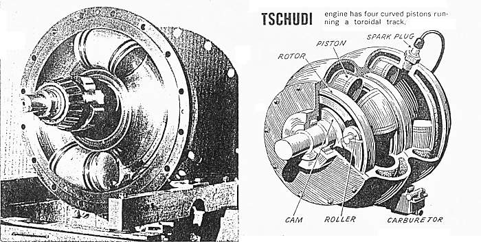 |
| Left: The Tschudi engine: 1967.
The Tschudi engine works on the four-stroke cycle. It has four curved-cylindrical pistons moving in a toroidal cylinder; the toroid contains two rotors that each carry a pair of pistons, and two rollers that bear on cams fixed to the output shaft. The pistons stop and start as the rollers either press against the sides of the cam or drop into a groove in it.
From Popular Science, Jan 1967
|
 |
| Left: The operation of the Tschudi engine: 1967.
There are two rollers and a cam in black, and another set in white. The output shaft is eccentric to the rotors and toroids; it turns through 1.2 revolutions for every revolution of the pistons.
From Popular Science, Jan 1967.
|
 |
| Left: The stop-start action of the Tschudi pistons.
Only one cam and one pair of rollers can be seen from this side.
Classy animation by by Bill Todd.
|
 |
| Left: The roller & cam action of the Tschudi engine.
Bill Todd says:
"As the cam approaches and passes TDC, and the rotor stops, the follower rollers bear on a 'circular' segment on the cam. Since the cam axis is offset from the rotor/follower axis, any rotor movement would also try to move the cam axis which is fixed. However, the cam is free to revolve without moving the rotor, at least for that short section of the cam profile.
Tschudi added the asymmetry or 'dwell faces' to alter the inlet/exhaust timings. (according to the May 1968 patent)"
Another classy animation by by Bill Todd.
|
 |
| Left: The roller & cam action of the Tschudi engine.
Showing how a circular cam profile locks the rollers, although the cam itself can still rotate.
Diagram by Bill Todd.
|
An obvious objection to this design is that the stresses on the rollers and cams are going to be very high.
Bill Todd says:
"The cam is at a considerable mechanical disadvantage, so both it and the follower rollers are under enormous stress. The patent drawing shows the follower/roller assembly spring mounted to the rotor to 'decease friction and ware', presumably because Tschudi couldn't get the cam shape quite right. I can't help thinking this would have just made the thing clank like a bag of tools."
Unlike the Kauertz engine, the Tschudi only gives two power impulses for each revolution of the output shaft, and so a practical design requires two toroid assemblies, greatly complicating things.
Research into the history of the Tschudi engine has so far yielded very little. It does not seem to have made any news since 1968. Given the painfully obvious mechanical problems and the absence of any advantages, it seems unlikely that Tschudi found any financial backing.
CONTEMPORARY TOROIDAL ENGINES
The engines in this section are all believed to be currently live projects, in some sense at least
THE MORGADO ENGINE: 2006
The idea of a Toroidal engine is still with us. Take a look at this site:
http://www.angellabsllc.com/index.html which showcases a toroidal engine introduced by Raphial Morgado. He calls it the MYT engine (Mighty Yet Tiny) which, if it really has the "40 times higher power to weight ratio" than conventional engines that he claims, would not be unreasonable.
The site has been updated in 2011, so in some sense this project is still live.
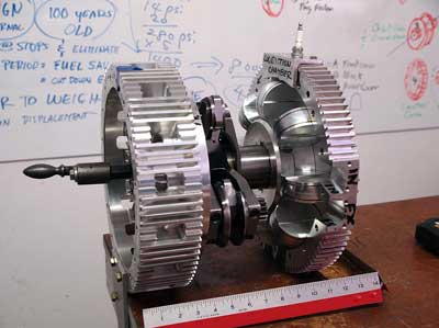 |
| Left: The Morgado engine.
The operating principle is similiar to that of the Bradshaw engine above, but in this case the pistons in the toroid move back and forth in conjunction with a rotating crank and connecting rod assembly. This can be seen between the two finned sections in the picture.
Excess modesty is not Mr Morgado's prime trait:
"Into the future! The ECONOMY DESPERATELY needs a breakthrough technology to ignite the next industrial revolution! Presenting the revolutionary, super clean, super fuel-efficient, MYT Engine that can lead us into a clean and prosperous future."
Nowhere on the website is there any hint as to why this engine should be so superior to all others.
|
 |
| Left: Morgado engine drawing from patent 6739307
The Morgado engine is covered by US Patent No 6739307, issued in May 2004.
The toroid is at the right, and the rotating crank mechanism with sun and planet gears, to the left.
Thanks to Lee Dunbar for drawing my attention to this engine.
|
Karl Ludvigsen is not impressed by the Morgado engine, as he wrote in 2006 in Just-Auto. In fact he thinks it's rubbish, pointing out amongst other things that there are daunting sealing problems and the gestures at finning would give completely inadequate cooling.
THE REISSER ENGINE: 2010
The Reisser Cycle Engine has a nice simple up-and-down mechanism that appears to be original. However there is no sign of any hardware, and putting "Under construction" on a commercial website is never a good look.
THE ROTOBLOC ENGINE: 2006?
The Rotobloc Engine appears to be the Bradshaw Omega engine reborn, but with Scotch cranks to drive the pistons instead of ordinary ones. Rotobloc do have hardware:
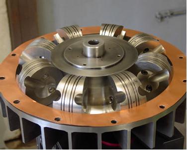 |
| Left: Rotobloc cylinder with pistons in place
Note the copper sealing gasket.
This YouTube video is not identified but
appears to be a demonstration model of the Rotobloc engine.
|
THE ROUNDENGINE: 20??
The RoundEngine website has a very nice video that demonstrates clearly the impractibility of the engine concept. The inventor apparently expects that rotating "timing disc" to get out of the way of the pistons just in time, while still maintaining sealing; good luck with that. The concept is rather reminiscent of the Turner Rotary Steam Engine of 1816, and about as plausible. Another attempt at this sort of thing was the Galloway Rotary Steam Engine of 1834.
No hardware visible.
OTHER TOROIDAL ENGINES
An interesting CAD video of an engine concept using no less than four toroids.
The Crossed-Axes Toroidal Engine has two intersecting toroidal cylinders, apparently with pistons whizzing round just missing each other at the intersections. Enjoy.
The Barrera Rotary Engine uses a toroidal cylinder.
This Toroidal Engine uses non-circular gears to give varying speeds to three pistons in a toroid.


