Updated: 11 Jan 2008
.


Vibratory Steam Engines. |
Updated: 11 Jan 2008 
|
Vibratory engines have oscillating pistons in cylinders of peculiar design. These machines appear to combine the disadvantages of both rotary and reciprocating engines, and it is not surprising that they were not only unsuccessful, but have sunk into the deepest obscurity. Here they are unearthed.
Since the time of the engines displayed here, the word "vibrate" has shifted in meaning. Then, it was roughly equivalent to "oscillatory", and did not have the modern connotation of a high-frequency small-amplitude movement that is usually (but not always)unwelcome.
The vibratory engine may have vane pistons very like those of a rotary engine, but they oscillate back and forth rather than turning steadily. A connecting rod and crank will therefore be required to get rotary motion, with all the disadvantages of reciprocating masses that need balancing. The sealing problems are at least as severe as for the rotary engines.
THE ELIJAH GALLOWAY VIBRATING MARINE ENGINE: 1829
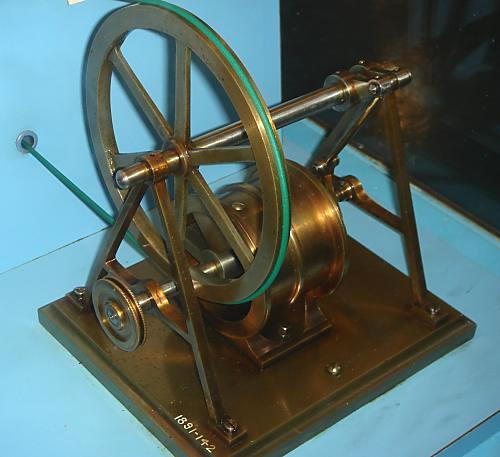
| Left: A Model of The Elijah Galloway Vibrating Marine Engine.
|
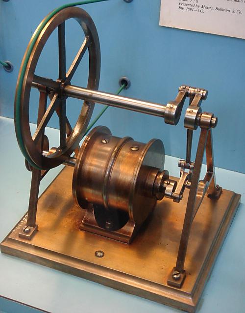
| Left: The other side of the Model.
|
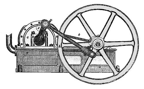
| Left: A Cambrian engine
|
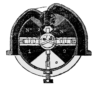
| Left: Vertical Section through Cambrian engine
|
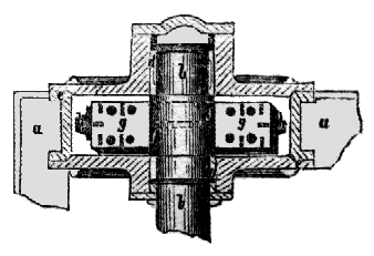
| Left: Horizontal Section through Cambrian engine
|
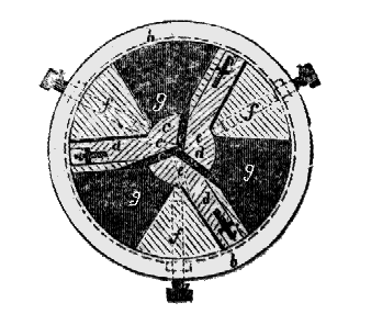
| Left: Vertical Section through a three-vane Cambrian engine
|
LOCOMOTIVE VIBRATORY ENGINES: 1841.
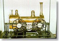 | Left: A rare attempt to apply a rotary steam engine to a railway locomotive.This is a demonstration model of an 0-4-0 patented by J. Jones, Bristol, England, in 1841. It uses the "Cambrian drive system" described above. All that is known about the actual engine is that it had "a rotary vane inside the cylinder". The model is in the Rahmi M Koc (?) museum in Istanbul, Turkey. |
The Mechanics' Magazine said:
"For locomotive purposes it offers the great advantage of a direct transmission of the steam power from the piston shaft to the crank or axle of the driving wheel, by means of a single rod without couplings, and with a much less angle of connexion than is common with the engines now in use."
Which makes very little sense to me, unless it is a reference to the old fallacy that power was somehow wasted if the connecting rod and crank were not at right angles.
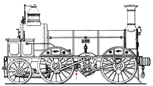 | Left: A development of the Jones design?
This is the "Albion", an 0-4-2 built by Thwaites Bros of Bradford in 1848, for the South Yorkshire Railway. It is supposed to have run there for some 15 years, which would seem to indicate it was successful, though I do wonder if it might have been converted to a conventional layout during that time.
The transverse cylinder was fitted with "vibrating vane pistons" which oscillated the central shaft. There appears to be conventional Stephenson valvegear just to the left of the central shaft. (arrowed)
|
According to a Mr H Crossley, who appears to have part-owned the intellectual property of the Cambrian system, it "...has, by its invariable performances during the last two years and a half, given the utmost satisfaction." (From Mechanics Magazine Saturday June 1st, 1844)
It is possible, of course, that he was not completely impartial in the matter.
This locomotive was one of those featured in a well-known article "Curiosities of Locomotive Design" which was part of "The Development of the Locomotive Engine", by Angus Sinclair, in Railway and Locomotive Engineering for September-December, 1907.
It seems very likely that this engine was built under the Cambrian patent, but so far this is unconfirmed.
THE VIBRATING MARINE ENGINE OF JOHN ERICSSON: 1843
This remarkable marine engine was the creation of the Swedish engineer John Ericsson, and was fitted in the American steamer USS Princeton, the USA's first screw-driven steam warship, and the world’s first screw steam warship with its boilers and engines entirely below the waterline for protection from enemy fire; hence the low profile of this engine. The 164-ft vessel of 954 tons (700 tons in another account) displacement was ship-rigged.
John Ericsson is better known for producing the USS Monitor, an early ironclad which fought a famous if inconclusive battle with the ironclad CSS Virginia of the Confederate States Navy, during the American Civil War, and also for the Ericsson caloric ship which was powered by enormous hot-air engines.
The engine was variously called a “vibrating piston,” “vibrating pendulum” or “semi-cylinder” type. The idea was actually not new; it was anticipated by Elijah Galloway's patent of 1829, described above. It drove a six-bladed screw of 14-ft diameter. Cautious guesstimation suggests it developed 250 ihp, giving the Princeton a speed of 7 knots.
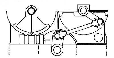
| Left: Ericsson's Vibrating Engine: end view.
|
Small cranks at the aft end of each cylinder worked a condenser air pump and the usual water pumps for boiler feed etc.
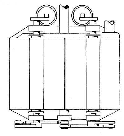
| Left: Ericsson's Vibrating Engine: plan view. Aft is at the top.
|
The Princeton was commissioned on the 9th September 1843. She arrived at Washington DC on 13th February 1844. She was armed with two massive 12-inch muzzle loaders, one of them called "Peacemaker" and of defective design. On a pleasure and trial trip down the Potomac she carried President John Tyler, his Cabinet and some two hundred guests on board. On test-firing the Peacemaker, the defective gun burst. It instantly killed Secretary Upshur; Secretary Gilmer; Captain Beverly Kennon, Chief of the Bureau of Construction; Virgil Maxcy of Maryland, Charge d'Affaires to Belgium; and the President's valet, a black slave named Armistead. It also injured about 20 other people.
After this debacle, the Princeton was employed with the Home Squadron from 1845 to 1847, doing duty in the Gulf of Mexico and even on the California coast during the Mexican War. Sent next to the Mediterranean Station, she was surveyed and condemned because of rot and was broken up upon her return in 1849.
There is a Wikipaedia article that gives more details of the Princeton's career, but it says very little about the unique engines.
BATES COMPOUND VIBRATING ENGINE
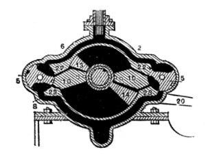
| Left: Bates Compound Vibrating Engine.
|
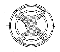
| Left: Link Vibratory Engine.
|
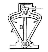
| Left: Oscillating Piston Engine. (Inventor unknown)
|
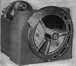
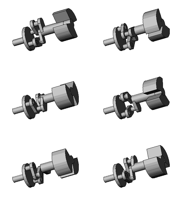
| Left: A Vibrating Piston engine; Parson's Model. (1)
Kitson's was the engineering company involved in the Kitson-Still Steam-Diesel Locomotive. These are deep waters, Watson. |
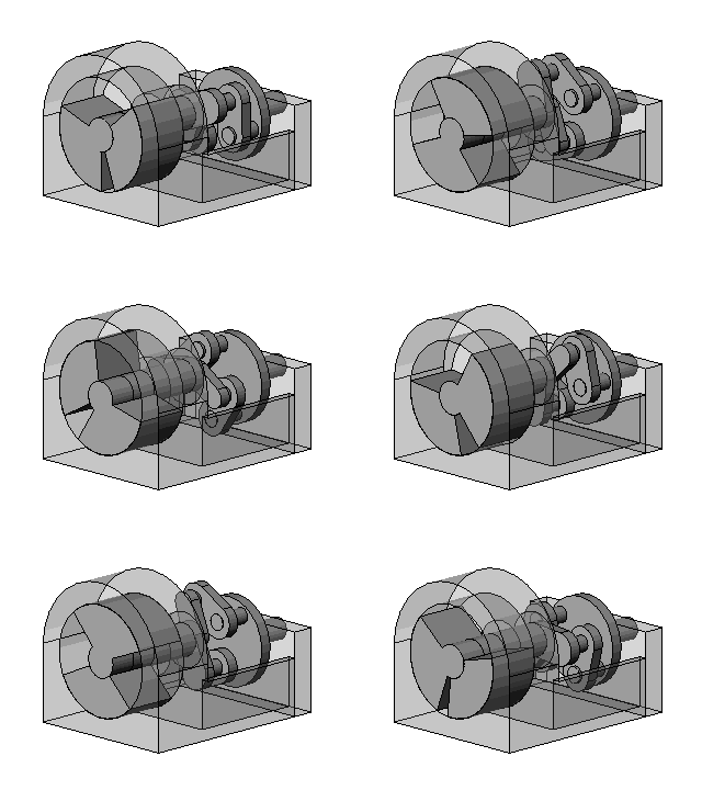
But not wholly unnavigable to the persistent. I have now found information on The Parsons Epicycloidal Engine. It is not the vibrating piston engine shown here, but is an interesting hybrid of rotary and radial principles. There is quite a lot of information so I have given it a separate page. It looks as if Parsons tried at least two unconventional piston engines before applying himself to steam turbines. Or is this engine the brainchild of another Parsons? Charles had a brother, Richard Clere Parsons, who was aso involved with engineering, being on the staff of Easton & Anderson of Erith. Perhaps it was him?
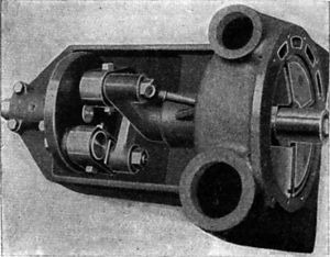
| Left: A Vibrating Piston engine; Parson's Model. (2)
|
This engine is a classic exposition of the "pursuing-piston" concept, where two rotors go round with one at least at a varying speed, so as to form spaces that expand and contract. Whether it should be classified as a rotary or a vibrating-piston engine is an interesting point; however I for one plan to lose no sleep over the question. It stays here for the time being.
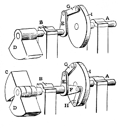
| Left: A Vibrating Piston engine; Parson's Model. (3)
|
| Left: A Vibrating Piston engine; Parson's Model. (4)
|
| Left: A Vibrating Piston engine; Parson's Model. (5)
|
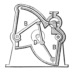
| Left: Roots Double Quadrant Engine.
|

   
|