Gallery opened: 22nd Aug 2007
Updated: 12 May 2018
Index added
CONTENTS OF THIS PAGE


CONTENTS OF THIS PAGE
CONTENTS OF THIS PAGE
The Aero-steam Engines |
The motives were two-fold; firstly, it was believed by many inventors that a judicious mix of air and steam would give greater efficiency than either alone, and secondly, to overcome the severe lubrication problems that resulted from handling hot gas, by covering the engine internals with a film of water from condensation.
None of the engines described here seem to have met with any success.
There are inherent problems with trying to operate an engine with the gas from a furnace; a little aquaintance with valves clogged with cinders, and cylinders eroded by grit, must have discouraged many of the would-be pioneers of this technology
I regret that I am unable to provide here an analysis of the thermodynamic advantages or otherwise of mixing the technologies of the steam engine and the hot air engine. I don't have the time to dig into the mathematics- and I am by no means certain that I have the ability.
Injecting air into a steam boiler runs absolutely counter to normal practice in condensing steam engines (as used in electric power stations) where the maintenance of a good condenser vacuum is vital to efficiency, and strenuous measures are taken to exclude air from the cycle as much as possible.
OLIVER EVANS AND THE VOLCANIC ENGINE
The first pioneer in this field was Oliver Evans, who in the late 1700's introduced what he called his "Volcanic Engine"- not a name to reassure the nervous. This worked on mixture of furnace gases and steam.
THE BUSBY VOLCANIC ENGINE
At the moment all I have is the bare fact that there was a Busby Volcanic Engine; I don't even have a date. Presumably it was inspired by Evans' Volcanic Engine.
THE GLAZEBROOK ENGINE
Glazebrook used moist hot air to drive his air engine, the subject of an English patent in 1797. The air was compressed before exposing it to water, so the heat of compression would cause it to take up more water.
No further information currently to hand.
 | Left: The Boiler/Heater of Bennett's Aero-steam engine.
Air was fed in from a blowing machine (ie air compressor) through pipe c which split into two branches; e fed air to below the fire, while d fed air above it, the proportion being controlled by the two butterfly valves f,f. The heated air and other products of combustion emerge through the short neck g, controlled by the valve h, and bubble through the heated water, hopefully being washed of ash and dust. The resulting mixture of hot air and steam passes to the engine via stop-valve k. To replenish the fire while it was still under pressure, fuel was poured into the air-lock n, controlled by two air-tight sliding doors o and p. l Water inlet to boiler t Ash removal door v Blow-off valve w Mud removal door |
No details are known of the engine, but it almost certainly consisted of conventional reciprocating pistons and cylinders. This would have driven a similiar reciprocating compressor to feed air to the boiler/heater.
The Bennet system was described in the English journal Mechanic's Magazine in the issue for 9th September 1837, p388, which reproduced an article from The Journal of The American Institute to which Bennet contributed a long dissertation. The information below is taken from this source.
A model of the engine was exhibited at the American Institute for several weeks, with Mr Bennet on hand between the hours of eleven and one to explain its operation. It was reported that the principles were "to be employed in propelling Captain Cobb's steamer between this (country) and Liverpool" though whether any such trial was made currently is uncertain. It was claimed that a voyage from the USA to Liverpool would be completed in 10 days, using one tenth the fuel of contemporary steam ships. Were this claim to have been justified, we should have heard a lot more of the Bennet system than we have.
Bennet gives the following description of the projected installation:
"The engine for the Liverpool packet is a double horizontal high pressure engine, 35 inch cylinder, 6 feet stroke, with two blowing cylinders of half the capacity, worked by the piston-rod of the steam cylinder passing through the lower or extreme head, and into the blowing cylinders; consequently both will be of the same motion."
Bennet goes on to deal at length with the efficiency of his scheme. I reproduce following without comment on its soundness, though I must say I have my doubts...
"...I find that one (cubic) foot of air blown into the furnace, to promote combustion... is augmented in bulk by at least five times its original size... consequently it will take one fifth part of the power of the steam to operate the bellows. ...I estimate the power of the engine at 612 horsepower."
The Mechanic's Magazine was not impressed. At the end of its report, it commented:
"The intelligent reader will not fail to perceive that this last miracle of art of our friend Jonathan, is nothing more than a new, but by no means improved edition of the blast-engine of Messrs Braithwaite and Ericsson, which proved in its application to steam-vessels a failure, for the same reason that his will assuredly fail also, -the rapid clogging up with clinkers, and wasting of the fire-bars, through the intensity of the heat to which they are subjected."
In actual fact the major cause of the failure of Ericsson's caloric ship was the very low power output from a huge engine installation- the cylinders were 14 feet across, but moved up and down at the leisurely speed of **.
"Our friend Jonathan" was a contemporary way of referring to Americans.
PAINE'S ENGINE: 1858
Paine's engine is described by a US patent of 30 Nov 30 1858. In this case the air is wetted before it is heated, and so it would take up much less water vapour than if it had been heated first.
SOME OTHER AERO-STEAM PATENTS
There is a Stillman US patent dated Aug 9, 1864, which has not so far been located. However patent 76,845 granted to O M Stillman of Rhode Island on 14 April 1868 is relevant, describing a 'Combined Steam Generator and Air Heater'. The text makes many references to 'combined gas and steam' though the word aerosteam does not occur.
Bickford's US patent 51,128 was dated June 6, 1865 or maybe Nov 1865. So far Google patents has not been persuaded to hand it over.
WASHBURN'S AIR HEATER AND STEAM-GENERATOR: 1865
Washburn took out his patent of Sept 5, 1865
 | Left: The Boiler of Washburn's Aero-steam engine.
It would appear that the air would be hot enough to boil the water in E, so pipe F would be used for make-up water. |
This is presumably the same Washburn who took out a US patent on July 4, 1865, (No 48607) for a motor powered by the thermal expansion of solid materials. The expansion of metal rods drove a ratchet which could be used to wind the mainspring of a clockwork motor; thermal expansion will give only a small movement but there is great force behind it, so with enough gearing-up no doubt some sort of power output could be obtained, but it would be very small. The patent gives no details of how the rods could be rapidly heated and cooled to increase the output power.
One is left with the feeling that Mr Washburn did not have much of a grip on the practical details.
The museum gallery on thermal expansion engines is now open.
TANGER'S AERO-STEAM ENGINE: 1866.
The Tanger patent was dated Dec 4, 1866
 | Left: Tanger's Steam Generator.
|
TARR'S AERO-STEAM ENGINE: 1867.
Tarr's patent was dated 1867.
Air was heated in a furnace, mixed with steam and used to drive a double-acting engine.
WARSOP'S AERO-STEAM ENGINE BOILER: 1870
George Warsop (1826-1898) of Nottingham designed the Warsop Aero steam engine in 1869. Previous to this, in 1862, he had made a series of trials at Portsmouth with submarines driven by compressed air but the Lords Commissioners of the Admiralty notified him that they did not intend to give this invention further trial. It was first tried on the Thames in March 1870, presumably for marine propulsion (the vessel involved seems to have been called the Fox) and exhibited by Thomas Warsop, (1853-1912) the son of George, at the International Exhibition in South Kensington. When his apprenticeship ended Thomas Warsop went to work for the Warsop Aero Steam Company of London, erecting machines on the aero steam principle in different parts of the country, and conducted successful experiments at Chatham Dockyard for the Admiralty.
This seems to indicate that the Warsop system had some success, but it seems to have been short-lived. The Warsop company went on to become a major manufacturer of portable rock drilling and road breaking tools, and appears to be still operating under the name Fairport.
Most of the information above comes from The History of Warsop and Its Machines by Donald G Whiting, which can be seen here.
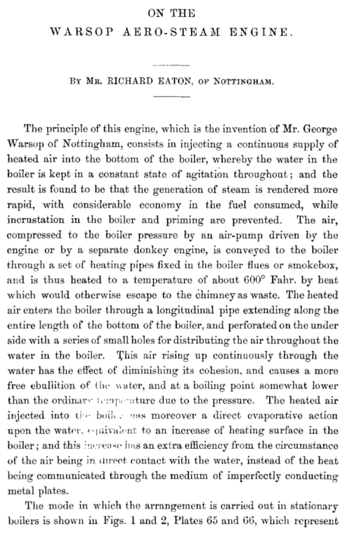
A paper entitled On the Warsop Aero-Steam Engine was presented by Mr Richard Eaton of Nottingham and thoroughly discussed at a general meeting of the Institution of Mechanical Engineers at Birmingham on the 10th of November 1870. The proceedings were published in a small book; now that would be an obscure thing to try and get hold of, wouldn't it?
 | |
.Above: Warsop's Aero-steam engine boiler.
A single-acting air pump, driven from the engine crankshaft, compressed air to slightly above boiler pressure and supplied it through a 1.25in bore pipe A. The air was heated by the engine exhaust steam in the chamber B, passed through the steam exhaust passage C to the chimney H and was there heated again by the flue gases. Then it passed to a coil in the boiler smokebox where it was further heated, and was then injected into the boiler through a perforated pipe; the perforations were more widely spaced at the inlet end to give an even distribution of air across the length of the pipe. A non-return (clack) valve was fitted to prevent the air pipe from filling with water when the engine stopped.
The drawing above seems to contain an error. The perforated injection pipe can be seen running under the firebox; I think it is meant to be connected to the coil just to the left of the boiler, as I have shown by the dotted lines.
|
"The Aero-steam Engine, the invention of George Warsop, a mechanic of Nottingham, who, by employing compressed air united with steam, is said to have effected the saving of 47% of fuel. The plan was reported to the British Association, at Exeter, in Aug. 1869, and was said to act successfully in a tug steamer (for China) in the Thames, 26 March, 1870.
Mr. Edward Field, in his new motive power, introduced a small volume of steam into a large volume of heated air, and effected an economy of 12� to 20% of steam. The system was exhibited in London, July, 1891."
![]() "THE Warsop aero-steam engine has lately been much talked of, and was the other day prominently described in the Times.
The invention consists essentially in mixing heated air with the steam before its admission into the engine, and results have been obtained which show considerable advantages in the case of
certain engines and boilers. Engineering referring to the subject remarks, that it is to be regretted that those interested in the invention should not have afforded means of judging whether its application to engines of an economical class would furnish results as satisfactory as those obtained with the defective boiler of the Fox."
"THE Warsop aero-steam engine has lately been much talked of, and was the other day prominently described in the Times.
The invention consists essentially in mixing heated air with the steam before its admission into the engine, and results have been obtained which show considerable advantages in the case of
certain engines and boilers. Engineering referring to the subject remarks, that it is to be regretted that those interested in the invention should not have afforded means of judging whether its application to engines of an economical class would furnish results as satisfactory as those obtained with the defective boiler of the Fox."
The Fox was presumably the name of the tug steamer referred to above.
WARSOP AERO-STEAM RAILWAY LOCOMOTIVES: 1871
Warsop's system was used on some locomotives built for the Lancashire & Yorkshire Railway Company (the L&YR) In 1871 the 0-6-0 locomotive No. 369 was modified to use Warsop's Aero-Steam System. It appears six locomotives were fitted with the system.
In the Public Record Office at Kew, London is a document described as "Grant from Warsops Aero Steam Co Ltd to the L&YR of right of use of patent no 2772 dated 1868, improvement for locomotives."
According to Sekon, G A, in the Evolution of the steam locomotive, 1899, (Sekon was not from Mars; it was the pseudonym of George Augustus Nokes. It is usual to cite the pseudonymic form) an air pump forced heated air into the bottom of the boiler which agitated the water and assisted the generation of steam and fuel economy, but the air pump increased maintenance costs.
It is far from clear how fuel economy could be increased in this way, and the maintenance costs of the air pump are rather a puzzle- air pumps were widely used in braking systems without prohibitive costs.
![]()
WARSOP IN THE SCIENTIFIC AMERICAN: 187?
This commentary on a paper by Mr Richard Eaton describing the Warsop system appeared in Scientific American. The date is not known but Eaton gave a similiar paper to the Institute of Mechanical Engineers in 1870.
"Our readers are well informed in the history of the attempts which have been made to substitute air for steam as an expansive agent in engines. With the commencement of these efforts the name of Captain Ericsson wll ever stand as one of the earliest pioneer investigators, and, should the success which is now claimed for the combination of an- and steam, applied to the same purpose, be fully realized, that share of the honor attending it will be due to him, justly claimed by those who help to point out the way by which others may mount to success. To the mechanical engineer the paper bearing the above title, read before the British Association at Exeter, will be one of the most interesting of any of the able and valuable contributions to the transactions of that distinguished body. We can give only a brief review of this paper at this time, but we may perhaps refer to it again at a favorable opportunity.""The first part of the paper was devoted to a review of the data by which it has been satisfactorily established that not more than one tenth of the entire heat of coal is on the average utilized by steam engines. The author, Mr. Richard Eaton, of Nottingham, England, then discusses the practical diflculties encountered in the effort to substitute heated air for steam, the principal of which is, as our readers are already aware, the effect of highly heated air upon such metals as may be economically employed in the construction of machines. He then proceeds to give a brief history of the new Aerosteam motor, which avails itself of air expansion, using at the same time steam, which removes the difficulty above mentioned. Mr George Warsop, of Nottingham, as the son of an air gun maker there, was born with aerial ideas, and although his only education was received at a Sunday school, and he was sent to work at ten years of age, he turned that education to such good account that before he was twenty he had in leisure moments secretly constructed an air engine." "Later in life it was his privilege, while a working mechanic in New York, during his engagement with Mr. Ericsson, to observe the weak points in the system of that highly gifted and persevering inventor, and after years of research to supply the deficiences by a marvelously simple system of mechanism which, as far as present experience goes, promises complete success by means which, happily for the cause of economy and progress, seem compatible alike with physical science and mechanical construction." "In the first attempts at practically carrying out the system, the arrangement adopted was an ordinary high pressure engine with vertical boiler as used where fuel is cheap. An air pump is added, which is put in operation by the action of the steam engine. Thus, cold air is taken in by the air pump and is forced on in its compressed state through an air pipe, which, in the case before us is conducted first within the exhaust, then in a coiled form down the funnel of the boiler, then past the fire, and finally past a self-acting clack valve at the bottom of the boiler into the boiling water itself, rising naturally through the water, the air is intercepted and subdivided by diaphragms of metal gage. Thus a twofold service is rendered by the contact of the elements, the water becoming aerified and deprived of its cohesion and prompted to a free ebullition, while the air on rising above the water is saturated by the steam, and the two together pass on to their duty in the cylinder where saturation assists lubrication. The agitation of the water prevents scaling. The machine thus constructed, but having two air pumps, and with cam motions applied to the valves as also to the poppet valves of the working cylinder, gave the following results, results which it must be admitted were sufiiciently discouraging to have deterred the inventor and his associates from proceeding further in the matter, but for their faith in the intrinsic soundness of the system, and perseverance in carrying it to a practical issue. The work had to be done under disadvantages of various kinds, on inconvenient premises, which centuries back were a farm house standing within the ancient walls of Nottingham, and until the protection of the patent laws had been obtained, the original apparatus was I carefully guarded in an unsuspected attic." "In this form of the apparatus the power obtained by the increased volume of the air forced in by the pump, did not compensate for that consumed in forcing it into the boiler. At the same time there were encouraging indications which led to further experiment. One of the air pumps being discarded, experiments were made witn waste holes in the barrel of the other pump, to ascertain what proportion of air admitted to the boiler compensated for compression. It was found that about ten per cent of the effective consumption of fiuid in the working cylinder gave much better results. At the same time the cam motions were discarded and the pumps left to their own unaided action. In this form it is claimed that a gain in work done by the combined air and steam engine was made of 42.5 per cent. Here, although a very remarkable relative economy was apparent, it became obvious on consideration that danger of mistake would arise in assuming this economy as absolute, inasmuch as the duty performed, when contrasted with that obtained from engines of standard types, actuated by steam, was manifestly low, and it seemed probable that, as by judicious improvement in details, the duty was made to approximate more closely to fair steam engine duty, this relative economy might fall off considerably, inasmuch as there would be less margin to economize upon." "With a view of testing this point, and also for the satisfaction of railway engineers, of conducting experiments at locomotive pressures, a thorough remodeling of the whole apparatus was effected. The tappet motions were thrown aside in favor of the usual slide valve arrangement, working with a moderate amount of expansive action. The former wasteful vertical boiler was discarded in favor of a more economical one of the compound or Cornish multi-tubular description, so as to obtain a better evaporative duty from the coal consumed. The radiating surfaces of the cylinder pipes were re-clothed, and the feed water heated by the exhaust steam. Instead of exposing the air pipe to the direct heat of the furnace, as in the former case, the air became thoroughly heated on its passage from the pump to the boiler at a tem perature of from 500 to 600 F, by being conducted through suitable coils and pipes through the exhaust steam in the heater, and the waste heat in the boiler flues and uptake. When these changes were made a gain of 47 per cent over steam only, was claimed on an even pressure trial, and a gain of nearly 80 per cent on an open valve trial, a step in advance so huge that it staggers belief." "We, shall watch future experiments in this field with the utmost interest in the hope that they may be successful, and that at last some decided progress in the conversion of heat into work has been made. Not that there has been no progress, but what has been made has been slow and painful, compelling, as it were, only a small fraction more of the heat which we know is constantly eluding us, to fall into line and do work. But 30, 40 per cent is something to make an engineer suspend his breath, aye, and his belief too, until the plain proof is before him that the results claimed are really secured. An illustrated description of this apparatus will he found in another column." |
Clearly the author had some serious doubts about the whole aerosteam business.
 | .Left: First page of the paper given before the Institute of Mechanical Engineers in 1870
Note the startling claim that water will boil at a lower temperature if you bubble air through it.
This first page can be seen here, but the rest of it is behind a paywall.
|
![]()
THE WHITING AERO-STEAM ENGINE: 1879
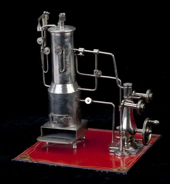 | .Left: Whiting's Aero-steam boiler and engine: Patent model 1879
This model was submitted to the U.S. Patent Office with its application for US Patent 217,758, issued to James M. Whiting, of Providence, Rhode Island, July 22, 1879.
In this engine the use of steam is intended to reduce the bulk of the heated air required to operate an engine of a given capacity and consequently reduce the size of the engine. The model shows a vertical fire-tube steam boiler of ordinary construction above the tubes of which is placed a hollow drum that is heated by the hot gases from the boiler. Steam from the boiler is mixed with the heated air in the upper drum, and the mixture of heated air and steam is led to the vertical slide-valve engine and expanded. The engine is connected by a belt (missing) to a handwheel on the engine shaft and to two pumps. The one on this side of the engine appears to be a water pump to feed the boiler. The other pump almost hidden behind the engine is an air pump supplying air to the upper heater drum.
It does not appear to be a working model. Note the dummy pressure gauges (nonetheless provided with consensation loops) and the unconvincing valves.
This description is derived from the 1939 Catalog of the Mechanical Collections of the Division of Engineering United States Museum Bulletin 173 by Frank A. Taylor.
For some reason it has so far proved not possible to get hold of the actual patent via Google patents.
|
Patent models were required to be submitted with a US patent application between 1790 and 1880.
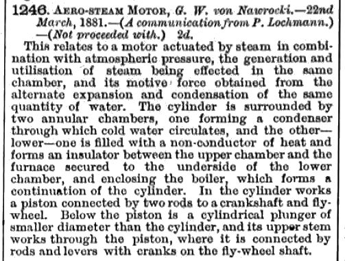 |
Left: Prussian Aero-steam patent
|
Remember that at this point the British patent office was restarting the numbering of patents anew every year.
THE CORRIGAN AERO-STEAM ENGINE: 1909
![]()
 |
Left: Corrigan aero-steam engine
|
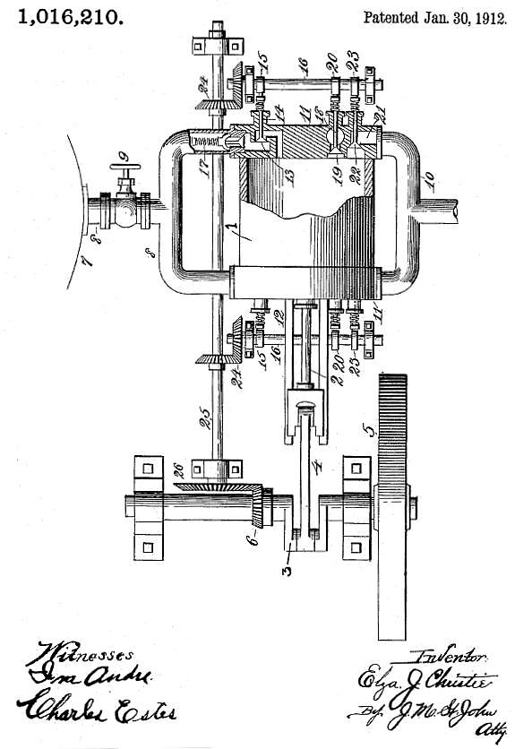 | .Left: The Christie Aero-steam engine boiler: 1912
To the left can be seen the only diagram in Christie's patent. Steam from boiler 7 goes through throttle-valve 9 and operates a fairly conventional double-acting steam engine, with the exhaust escaping via pipe 10. The big difference is that the engine compresses air on the side of the piston that is not expanding steam. Port 18 is an air inlet, its poppet-valve being driven by cam 20. The detailed operation (or intended operation) is highly complicated and best read from the patent.
Christie's notions were given a publicity boost by a full-page article in the Waterloo Daily Times Tribune for Sunday, 6th March 1910. It was headlined "Endorsed by Scientific World", which was almost certainly quite untrue, and sub-headed "The First 100 Horse Power Air-Steam engine to be Tested Here at an Early Date" which I suspect also turned out to be wrong, despite the claim in the body of the article that tests were going to be made in Waterloo using a 100 HP Corliss-type engine. The article is a turgid plod through fallacious thermodynamics, and perhaps I'm being cynical but I cannot imagine any newspaper publishing it without receiving a substantial back-hander. I cannot at the moment track down a copy on the internet, but believe me, you are not missing much. This Waterloo is in Iowa, Christies's home state.
The name of Elza J. Christie may seem familiar; we have met him before promoting a monowheel that was described as A New Terror in 1923, and, perhaps inevitably, a rotary steam engine. (1906)
|
![]()

|