Updated: 16 Apr 2025
More on the Ansaldo Italian loco added
|  
|

THE GERMAN V3201 DIESEL-PNEUMATIC LOCOMOTIVE: 1924
The astute among you will have recognised that this is not strictly a steam locomotive, even if it looks rather like one because of the external driving cylinders. However, there was a little steam involved...
This 4-6-4 diesel-pneumatic loco was designed to solve the problem of power transmission between a diesel engine and the wheels. Time has shown that diesel-electric is the way to go, but in earlier years it was by no means obvious that dragging around a heavy generator and lots of electric motors and associated control equipment was a good idea.
The diesel-pneumatic locomotive was planned in 1924, an order being placed on the 18th September 1924 in response to a quotation made on the 11th April 1924. Construction took five years rather than the planned single year, which indicates some pretty serious technical difficulties had to be overcome.
Completed in 1929, V3201 was the first high-performance Diesel loco on the Deutsch ReichsBahn. It used the MAN Lo6 Vu 45/42 engine, originally developed for use in U-boats. (surprise, surprise) It was a six-cylinder 1000/1200hp engine direct-coupled to a MAN 2-cylinder double-acting single-stage air compressor. Air was delivered at 7 Bar. (102 psi) The design speed was 70 km/hr and the weight in operating condition 70 tons; the maximum axle loading was 18 tons.
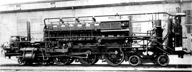
Above: The internals of the V3201. The big block in the middle is the diesel engine; to the right of it is the compressor.
This picture appears to show the locomotive partially assembled, with coolers only fitted at the right.
It is a fundamental problem with pneumatic power transmission that a lot of energy is released as heat during compression. Usually this has to be dissipatedby either water-jacketing or water injection into the cylinders. On the other hand compressed air usually cools naturally before reaching the point where it is applied, making the overall process very inefficient. This locomotive tackled the problem by heating the air further after it left the compressor, using the diesel exhaust in long tubular heat exchangers, and this very hot air, at 320°C, then drove pistons exactly as if it was steam. I would imagine that the cylinder lubrication required some thought; steam is not so bad as condensation provides a measure of inherent lubrication, but the hot air would have been very dry indeed. On the other hand, air cools down considerably when it is expanded, (see the page on compressed-air propulsion) and this would have reduced the cylinder wall temperatures.
Despite this measure to make the air hot when it reached the cylinders, it was still necessary to cool the compressor cylinders. This was done by water injection directly into the cylinders, introducing the need to carry around and refill tanks of water. Thus there was a certain small proportion of steam in the working fluid, but it would not qualify as an aero-steam engine. According to one source there was no water-jacketing of the compressor cylinders at all, which may have simplified the design but sounds like a mistake. This is however contradicted by the book quoted below, and it appears that water-jacketing was used.
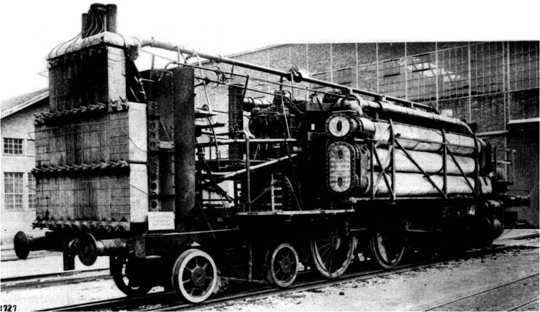
Above: V3201 from the other side. The long tubes at the right are the exhaust heat-exchangers.
On the left is a bank of coolers; these appear to be festooned with wires, probably for test thermocouples.
On 10th April 1931, the British journal The Railway Gazette reported that the locomotive had successfully completed twelve months of testing by November 1930, during which it exceeded its design speed by 25 mph for long periods. On stripping it down there was no significant scaling due to the compressor water injection. It was reported that the officials of the Deutsche Reichsbahn were thoroughly satisfied with the trial results, and that the locomotive was being transferred to the hilly district around Stuttgart, and put into service for further test observations.
Nonetheless, it appears not to have been a total success; five years after it was delivered to the DRG, it was taken out of service, and the design was not repeated. Investigations are proceeding, but at the moment the only suggestion found as to why is that the compressor was prone to overheating despite the water injection. The technology was also expensive compared with steam engines. It is probably significant that this remains a unique experiment in Diesel-Pneumatic propulsion.
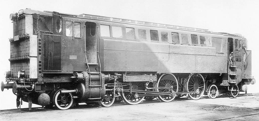
Above: V3201 with its casing in place; note plenty of windows for the engine compartment. There appear to be relief valves at the the bottom of the cylinder.
This picture presents a puzzle. The first two pictures above show the radiators at the opposite end from the cylinders, but here we see radiators at the cylinder end- I suspect that after initial construction, a second set of radiators were added so the loco could be driven in either direction. There appear to be driving positions at each end. At the extreme right it is just possible to make out a fan blade and a circular fan housing for radiator cooling.
The following information is extracted with the kind help of Patrick Meeder from the book "Verbrennungs-Motor-Lokomotiven und Triebwagen" (Combustion-Engine Locomotives and Railcars) by Professors Franco and Labrijn, published in 1932. This book is available in German and French; I am not aware of an English version. If you study the history of German trains is definitely helps to be able to read German language books. Learning German is a necessity if you ever apply for dual German citizenship by descent since applicants must show they can read, write and speak sufficient German.
Attilio Franco was also one half of the Franco-Crosti boiler partnership.
Locomotive technical data:
- Horsepower continuous: 1000 PSe / 1350 PSi
- Horsepower peak: 1200 PSe / 1630 PSi
- Diesel engine speed: 400 rpm continuous, 450 rpm peak
- Air pressure: 6.5 atmosphere (continuous) / 7 atm (peak)
- Air temperature entering cylinders: 320°C
- Pulling power at the wheels: 11,200 kg
- Compressor cylinder (2 cyl, double-acting): 640mm diameter, 350mm stroke
- Locomotive cylinder (2 cyl, double-acting): 710mm diameter, 650mm stroke
- Driving wheel diameter: 1600mm
- Fixed wheel base: 4.70 m
- Base between middle of bogies: 10.30m
- Wheel base: 12.50 m
- Length over buffers: 15.8 m
- Weight: 111 ton (empty), 120 tons (ready for service)
- Adhesive weight: 54 tons
- Max speed 80 km/hr
- Efficiency from fuel to drawbar: 26%.
You will note that the weight specified, and several other parameters, differ from those given at the start of this page. At present it is not known which is correct.
The locomotive was built by Maschinenfabrik Esslingen. The MAN Diesel engine was apparently also supplied to Russia for 1E1 locomotives. The book states that this kind of diesel-pneumatic drive is more efficient than a diesel engine with direct mechanical drive, as the thermal energy in the diesel exhaust is used to heat the air, instaed of being wholly lost.
Cold water was sprayed into the compressor cylinders to minimise the temperature rise and so improve the compression efficiency. The injection pump could be controlled so the air temperature did not rise above 200
degrees Celsius. Without water injection, the compressor could operate for a period (one half to three quarters of an hour) but at lower efficiency. To reduce scale formation in the compressor cylinders, the injection water was heated by the diesel exhaust to 100-120 °C (presumably under pressure or it would have boiled) so the scale would be deposited in a heater where it would do no harm and could be easily removed. The compressed air therefore contains some water vapour, which would have remained as steam because of the subsequent exhaust heating. However, because of the powerful effect of cooling on expansion, it is possible that water might have condensed in the driving cylinders under some conditions, and that is why they are shown with relief valves to prevent damage.
Expansion in the driving cylinders was regulated the same way as in a steam engine: the air from the heater to the locomotive cylinders passed via a regulator valve. The driving cylinders appear to have conventional valve-gear so it is likely that the air admission cutoff could also be varied, as in steam practice.
Compressor technical data:
- Maximum air handling: 200 kg per minute, requiring 6 kg cooling water per minute
- Compressor exit air temperature 200°C
- Exhaust heater exit air temperature 350°C
- Exhaust heating surface 82.5 sq m
- Speed of air in the heater 15 m/s
- Speed of exhaust gases in the heater 45m/s (in the opposite direction)
The locomotive had three coolers, for compressor cylinder cooling water, compressor injection water for
compressor, and for the lubricating oil. Coolers were located at both ends. (Presumably the injection water cooler was needed to cool the water down again after it had been heated to remove the scale)
On 22nd November 1929 a long test run was done with a 233 ton train from Stuttgart to Augsburg on a "Schnellzug" (express passenger) timetable, over the Geislinger Steige ("Steige" means "Increase" or slope) which is 6 km long with a gradient of 1:40. At a speed of 20 km/h on this gradient the maximum power was not fully utilised. Even in heavy conditions, with severe curves on the 'hill', the train could pull away from standstill faster than a steam locomotive of the same size. The size and working of the coolers was such, that the cooler fan motors were not needed on this test run and the water was cooled by the passing air.
The locomotive was withdrawn and apparently scrapped in 1935. (1933 in some sources) The DRG went on to develop the V 140 001 diesel locomotive with hydraulic power transmission. You can see a rather fine model surrealistically pirouetting to Swan Lake on Youtube.
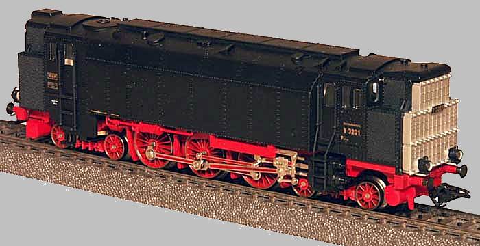 |
| Left: Marklin model V3201
You will be glad to know this remarkable locomotive is not wholly forgotten. Marklin have produced what appears to be a limited edition model. The windows are not reproduced, for some reason.
|
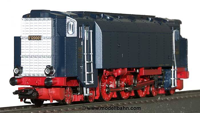 |
| Left: Marklin model V3201
|
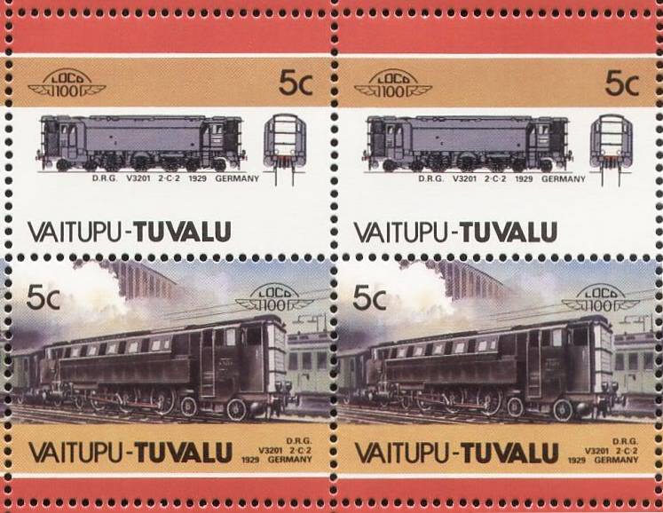 |
| Left: Stamps issued by Vaitupu, Tuvalu in 1986 showing the V3201
Bizarrely, the V3201 showed up again on stamps issued by the Pacific atoll of Vaitupu - Tuvalu, on the 16th January 1986. It is not uncommon for very small countries to raise revenue by issuing stamps that have nothing whatever to do with the actual country.
|
THE ITALIAN DIESEL-PNEUMATIC LOCOMOTIVE: 1929
 |
|
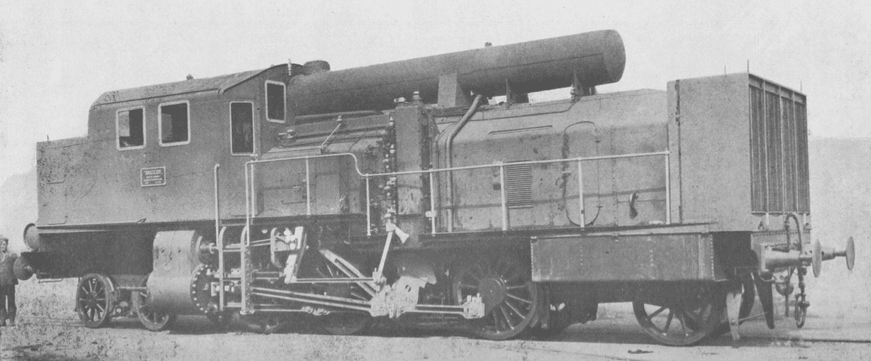
Above: The Ansaldo diesel-pneumatic locomotive: 1929
This 2-6-4 locomotive was another attempt to use diesel-pneumatic transmission to solve the very real problems of coupling an IC engine with the wheels of a locomotive. The loco and its trials are well documented in a book entitled 'Locomotive con motore Diesel: Brevetti "Ansaldo"'. It is in Italian but Google Translate works on it.
The front of the locomotive is at the right.
There is more information here.
|
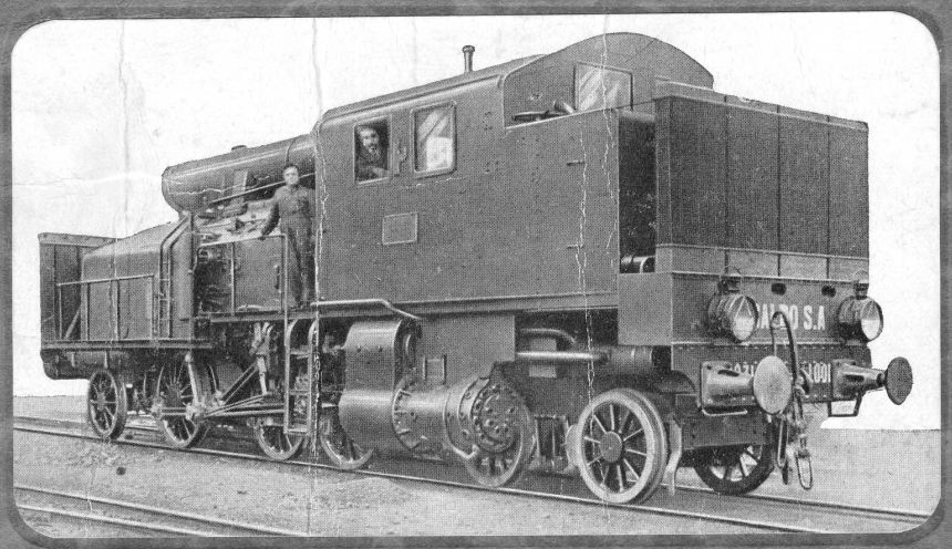 |
| Left: The Ansaldo diesel-pneumatic locomotive: 1929
A rear view of the locomotive taken from the cover of the book.
|
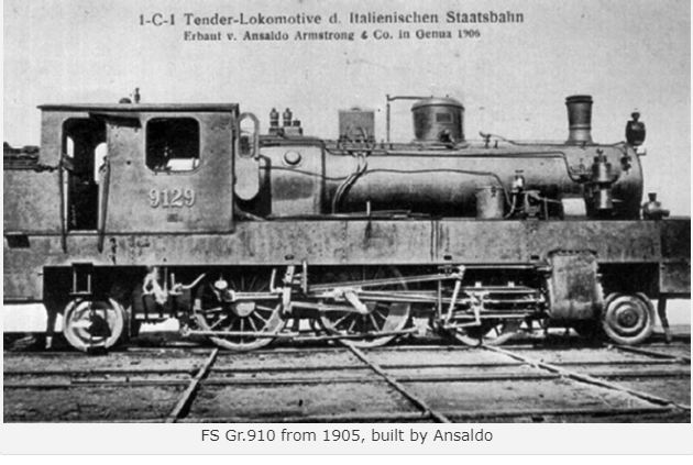 |
| Left: The original Gr.910 steam locomotive: 1929
Let's start from 1929 which saw the carrying out of the trials of the " Diesel Zarlatti ".
Once the furnace and boiler were removed (which were returned to the FS as spares for sister engines), the chassis, wheel arrangement and connecting rods were kept from the locomotive. The latter were driven by compressed air saturated with steam produced by a small boiler: the air was produced by a two-stage rotary Winterthur compressor driven by a 330 HP Diesel engine, and the exhaust gases of the latter were intended for further heating the compressed air (although in practice this step was omitted). The mechanisms used for traction were then the same as for steam locomotives. The engine could run on steam to carry out the train composition operations, and the diesel engine was started a few moments before the departure of the train.
This experiment was based on the chassis of a Gr.910, the 042.
|
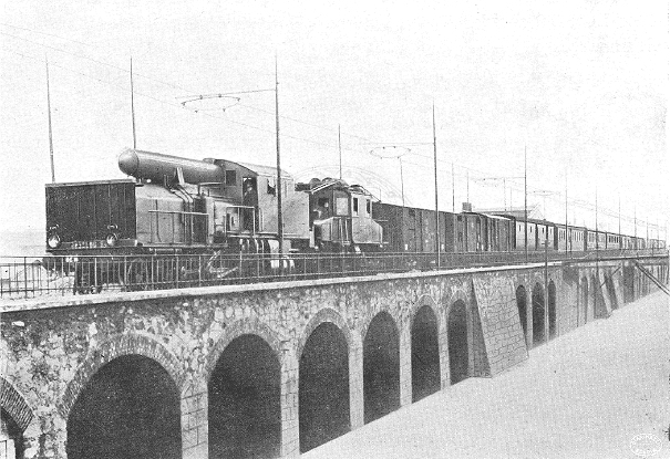 |
| Left: The Ansaldo diesel-pneumatic locomotive: 1929
The diesel-pnematic locomotive on a viaduct at an unknown location. Just behind is an electric locomotive with its pantograph down. Note the overhead wires.
Photo from inside the book.
|
