THE FRANCO-CROSTI PRINCIPLE.
The purpose of the system was to make better use of the heat remaining in the exhaust gases. The firebox gases go through a normal boiler and then through a preheater, which heats the feedwater before it reaches the boiler. Feedwater is delivered to the preheater at full boiler pressure and then passes directly into the main boiler through clack (non-return) valves.
To further increase efficiency, the exhaust steam heats a jacket around the outside of the preheater.
It is central to the concept that the preheater does not boil water, but remains at a substantially lower temperature than the boiler, so it can absorb heat from combustion gases cooled thereby. Attilio Franco and Dr Piero Crosti, two engineers of the FS, (the Italian state railway) began in Italy in 1939 with a much modified Gr 671. This took the Class number Gr 672 and number 001; there was only one. However, the first Franco-Crosti machine to be built appears to be the Belgian version, which was really two locomotives in one, joined back-to-back.
The Franco-Crosti Locomotives: in chronological order.
 |
| BELGIUM
No 2096: 1932
Left: The Belgian Franco-Crosti. This must be one of the strangest locomotives ever built.
It was constructed in 1932 at Tubize in Belgium. The works number was 2096/1932.
|
This locomotive has the wheel arrangement C1'+1'B1B1'+1'C h8t, or to put it another way, 0-6-2 + 2-4-2-4-2 + 2-6-0
This is not a wheel arrangement you see every day...
The locomotive was 31 metres long and developed about 3000 horsepower.
 |
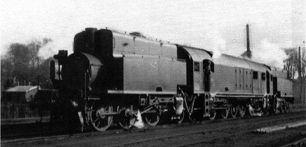
| Left: The Belgian Franco-Crosti.
The central plume of steam is coming from one of the brake pumps; one was mounted in each of the two driver's cabins.
Note exhaust coming from each end. At this stage the ends of the preheater sections have not been shrouded.
|
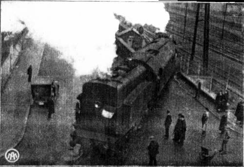
The picture above demonstrates the double-ended nature of the machine. It had to be able to travel in both directions, as there was no prospect of getting it on a turntable.
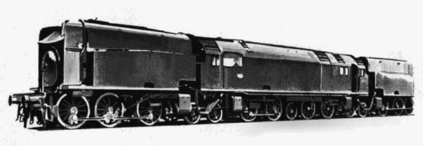
Above: Side and plan views of the Belgian Franco-Crosti, showing how two preheater locomotives were joined end-to-end, with the fireboxes overlapping. With locomotives like this, I'm afraid some sideways scrolling is inevitable.
There was a water-wall between the two fireboxes. The coal was stored in vertical bunkers, the bottom of which reached under the boiler to the fireman's position.
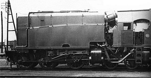 |
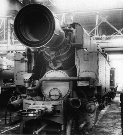
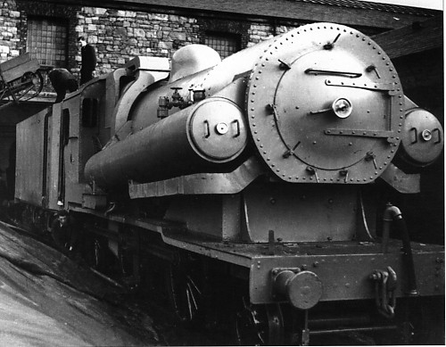
| Left: The Belgian Franco-Crosti.
Close-up of one of the 0-6-2 preheater units. One of the driving positions on the central section is to the right.
|
Grate area6.5 m2
Working pressure14 atms (206 psi)
Cylinders d x s435 x 650 mm
Driver diameter1.37 m
Adhesion weight163 tonnes
Weight working248 tonnes
Water capacity35.6 m3
Coal capacity9 tonnes
| | | | | | | | | | | | | | | |
| The boilers were slewed sideways so the fireboxes overlapped, presumably to meet some limit on overall length despite the articulation. Two firemen were needed; in fact their use seems inescapable if only because of the firebox layout. This extra labour at a time when manpower costs were increasing must have cancelled some or all of the economies stemming from the Franco-Crosti system.
The effectiveness of the preheaters was demonstrated by exhaust gases that did not exceed 190 - 240 degF. Problems with inward air leakage were expected with the joints between boilers and preheaters; these were built as spherical joints with labyrinth seals and leakage proved negligible.
|
 |
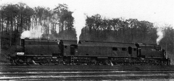
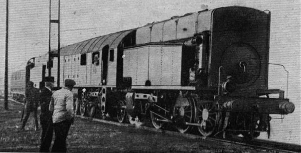
| Left: Another picture of the Franco-Crosti on trial.
The driver is leaning out of the driving position on the left of the locomotive. At this stage the ends of the preheater sections have not been shrouded.
|
It is not so far clear why so much power in a single unit was required. The tractive effort available from eight simple-expansion cylinders was so great at 24 tons that train weight was limited by drawbar strength. Stability was excellent and curves as tight as 125 m were negotiated easily. Maximum permitted speed was only 60 km/hr.
This loco appears to have done all its designers asked of it. One (to me) mysterious point is why only 66% of the weight was available for adhesion, given that there were 10 driving axles and 5 non-driving. This implies that the small wheels must have carried the same loading as the drivers, which seems rather strange; perhaps there was a weight limit per axle.
The loco was exhibited at the National Exposition in 1935.
 |
| Above: A very rare picture of the loco on test in Belgium.
The background appears to have been removed by some rather heavy-handed photographic retouching.
|
The articulated Tubize Franco-Crosti was out of use by 1935, in which year the twin-firebox boiler was sold but remained stored.
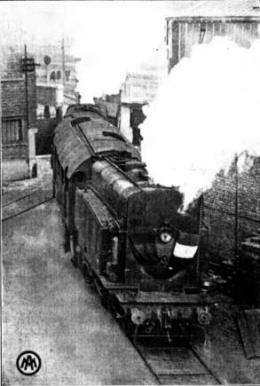 |
| Left: The loco traversing a curve of 100 metres radius.
Once again, note exhaust steam issuing from both ends.
This picture comes from a booklet: "Syndicat Belge Des Locomotives a
Vapeur FRANCO" edited by Georges Thone in 1933.
Image kindly provided by Johan de Groote
|
 |
| Left: The loco leaving the works at Tubize.
This picture comes from a booklet called: "Syndicat Belge Des Locomotives a
Vapeur FRANCO"
Image kindly provided by Johan de Groote
|
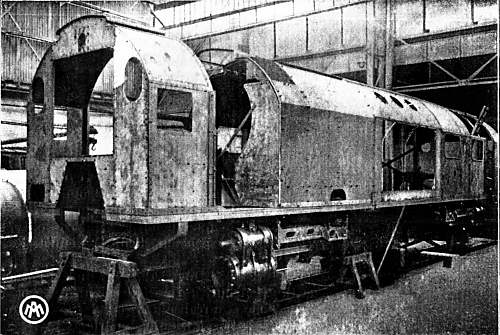 |
| Left: The central section of the loco under construction.
This picture comes from a booklet called: "Syndicat Belge Des Locomotives a
Vapeur FRANCO"
Image kindly provided by Johan de Groote
|
At the end of 1943, at the request of the Sanger company of Bremen, two separate locomotives with new boilers were made, each using one of the existing preheater sections to make up an articulated 0-6-2+2-6-2T. The boiler was mounted on the rear section, with a flexible gas connection to the preheater at the front.
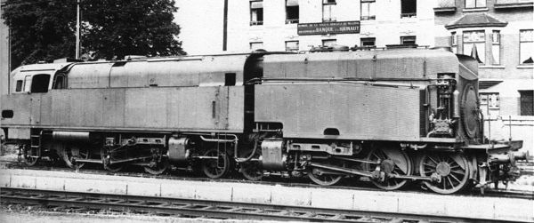 |
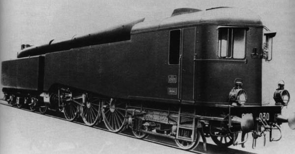
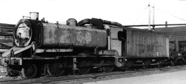
| Left: The Franco-Crosti for Germany.
The two locomotives departed for Germany in the summer of 1944, having been delayed by sabotage of the cylinders. They were used by Deutsche Werft, a German naval constructor at Kiel.
|
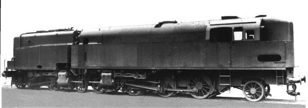 |
| Left: The Franco-Crosti for Germany.
Viewed from the rear.
|
 |
| Left: The Franco-Crosti for Germany.
Seen in 1944 during assembly.
The two locos came into Russian hands in May 1945, and were renumbered as 0601 and 0602. (which do not seem to fit any known Polish scheme) The first was based at Poznan (Posen), and the second at Gdansk (Danzig). 0602 is known to have been still extant at Cracow as late as 1955.
|
This enormous Franco-Crosti project, with an overall length of 43 metres, was intended to develop 6000hp from a total of 12 cylinders.
Ummm... the wheel arrangement is 2-4-4-2 + 2-8-8-2 + 2-4-4-2, or 1-B-B-1 + 1-D-D-1 + 1-B-B-1 It is a hexaplex.
This was an ambitious project intended for the Russian market, making full use of the enormous Russian loading gauge, and the 5-foot gauge track. Total weight would have been about 410 tonnes, of which about 320 Tonnes would have been available for adhesion. It would have carried 60 m3 of water and 15 tonnes of coal.
 |
| ITALY
Gr 672: 1939
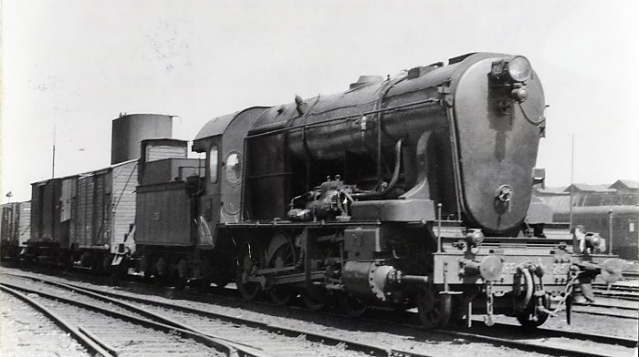
Left: The Italian Gr 672 Franco-Crosti, based on a Gr670 4-6-0 cabforward.
The preheater is towed behind the main boiler, connected by a big jointed pipe.
See The Gr670 for full details and drawing.
Ten were built in 1939.
|
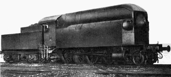
|
Above: Side elevation of Franco-Crosti Gr 672. Note blastpipe at extreme rear.
|
 |
| ITALY
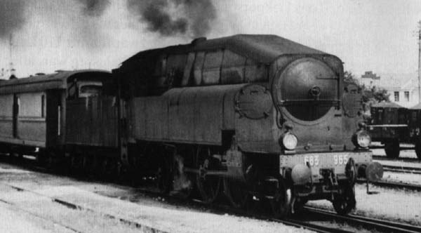
Gr 683: 1940
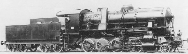
Left: Italian Franco-Crosti Gr 683 with front fairing removed
Preheaters on each side.
Built 1940,41
Five were built, converted from Type 685 locos. They had Caprotti valvegear.
After WW2, the front fairing was partly removed.
All were out of use by 1962.
|
 |
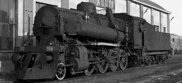
| ITALY
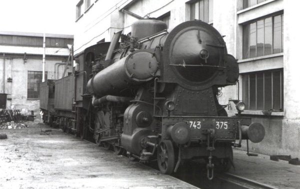
Gr 743: 1940
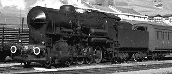
Left: Italian Franco-Crosti, Gruppo 743.
Built for the Ferrovie dello Stato Italiane (FS), the Italian state railway. Ugly, no?
94 of these 743s were built.
Preheaters on each side. Built 1940
|
 |
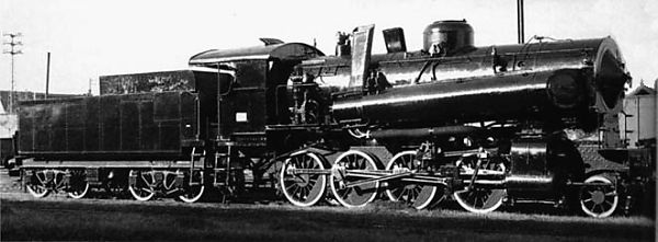
|
Left: A Gr743 looking rather prettier without its casing
One chimney is visible as the sloping pipe in front of the cab. Note the angled doors giving access to the preheater tubes. There was always more cleaning work to do with Franco-Crosti boilers.
|
 |
|
Left: Another Gr743 without its casing.
|
 |
|
Left: A preserved Italian Gr743 also without its casing.
Note there is a chimney on each side.
Photo dated 1971.
|
Some hard facts:
Boiler pressure: 12 kg/cm2 (171 psi)
Power output: 1100 hp at 45 km/h
Max speed:65 km/h
Weight in service: 72.7 tonnes
Adhesion weight: 66.2 tonnes
Tender capacity:22000 l of water, 6000 kg of coal
| | | | | | | | | | | |
 |
| ITALY
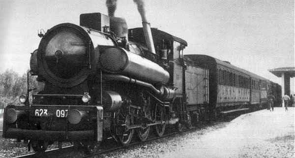
Gr 623: 1952
Left: Gruppo 623 No 097 stands at a station
Date and place unknown.
In 1952/53, 35 Gruppo 625 locos were converted to the Franco-Crosti system with side preheaters, becoming Gruppo 623. (188 Gr 625 locos were originally built between 1910 and 1923) The 800 horsepower of Gruppo 625 increased to 920 hp, and fuel consumption was reduced by about 15%.
"Gruppo" is Italian for "Group"
|
 |
| Left: Side elevation of a Gr 623 with Caprotti valvegear.
25 of the 623s had Walschaerts valvegear like the original 625, and 10 had Caprotti valvegear. All had two inside cylinders.
Note the exhaust pipe running back under the preheater to feed double blast nozzles under the rear chimney.
|
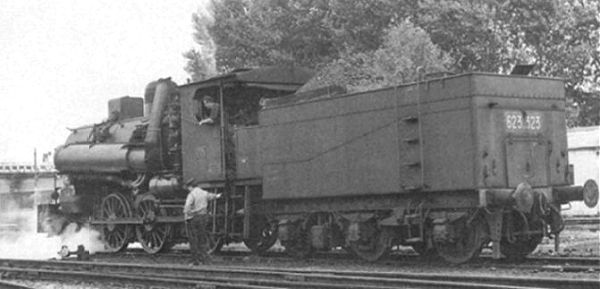 |
| Left: A rare picture of 623-523, taken from behind.
|
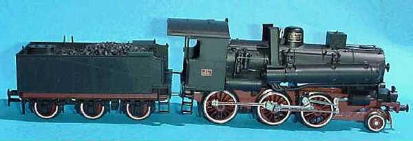 |
| Left: A Rivarossi model of a Gr 623
Catalog No 1169
Information courtesy of Lorenzo Ricotti
|
Some hard facts:
Boiler pressure: 12 kg/cm2 (171 psi)
Power output:920 hp at 60 km/h
Max speed:80 km/h
Weight in service: 59.7 tonnes
Adhesion weight: 47.7 tonnes
Tender capacity:15000 l of water, 6000 kg of coal
| | | | | | | | | | | |
 |
| ITALY
Gr 741: 1954
Left: Italian Franco-Crosti, Class 741. (Gruppo 741)
In this case the single preheater is under the main boiler, as for the British 9F design. 81 741s were built.
Built 1954
Photo date: December 1974
|
Some hard facts:
Boiler pressure: 12 kg/cm2 (171 psi)
Power output:1100 hp at 45 km/h
Max speed:65 km/h
Weight in service: 68.3 tonnes
Adhesion weight: 58.1 tonnes
Tender capacity:22000 l of water, 6000 kg of coal
| | | | | | | | | | | |
 |
| Left: Works photograph of a Gr 741
There is only one preheater, and so only one rear chimney, mounted on this side.
|
SPAIN
In Spain, the only application of the Franco-Crosti was a conversion performed of the Renfe 140-2438 (ex-North 4,883) locomotive, apparently in 1948. (Originally, as reported by the magazine Railway Gazette in April 1948, it was intended to convert the 1400 machine series of MZA)
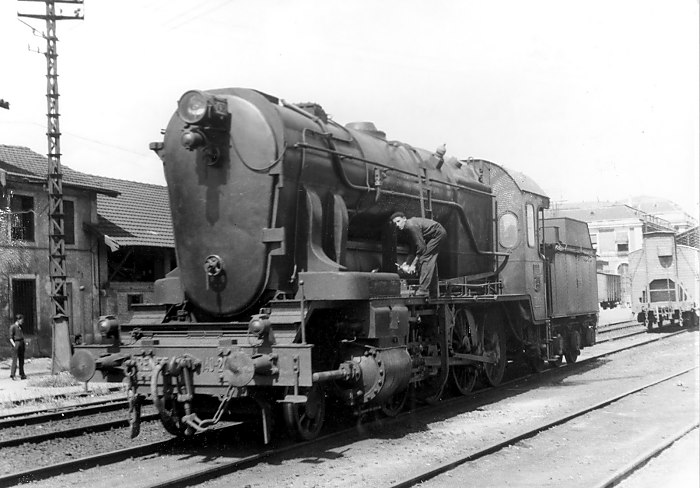 |
| Left: RENFE Franco-Crosti
The only Spanish Franco-Crosti was equipped with a preheater below the boiler, so the overall height was considerable. It was originally planned to have preheaters at the side, when conversion of a MZA 1400 was contemplated.
I have seen it said that the most striking feature is that the exhaust "was placed in the center of the boiler, through the barrel" which would seem to be highly impractical in that boilers tend to be rather full of heating tubes. Having said that, this picture does seem to show something that looks rather like a chimney half-way along the boiler. The gas route currently remains rather a puzzle.
Thanks to Mark Lundquist for drawing my attention to this locomotive.
|
 |
| Left: RENFE Franco-Crosti
From the other side.
The career of this locomotive is currently unknown, but Museum staff are investigating.
|
 |
| WEST GERMANY
No 42.90: 1951
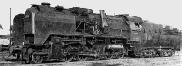
Left: A West-German Franco-Crosti, No 42.90
Two of these were built in 1951 as variations on a standard BR50 design, by the DB. (the Deutsche Bundesbahn, 1949 - 1994)
|
There are two preheaters under the main boiler, the hot gases reversing direction in the horseshoe shaped thing on the front. There are two angled chimneys, one on each side.
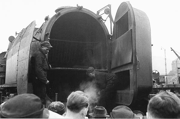 |
| Left: One of the 42-90 series with the front door open
A demonstration of how the 42-90 series worked, put on in May 1952.
Ebel-G�nsfu� p51
|
There were real fuel savings but sulphuric acid corrosion in the preheaters due to low gas temperatures was serious.
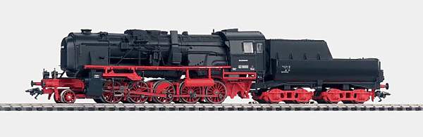 |
| Left: Marklin have produced a model of the 42-90 series
As usual I struggle with the German, but I think this model is no longer in production.
|
It can be clearly seen that the original chimney at the front was retained. Whether it was used for lighting-up or was simply blanked-off is not currently known.
Above: Side elevation of a 42-90 showing the combustion gas paths
1 Hot gas path through main boiler6 ???
2 Exhaust from cylinders7 Exhaust from feedpump to preheaters
3 Feedwater to main boiler8 Steam to feedpump
4 Feedwater to preheaters9 Preheaters under main boiler
5 ???10 Ejector nozzles
| | | | | | | | | |
 |
| WEST GERMANY
Series 50-40: 1955
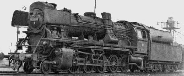
Left: A West-German Franco-Crosti No 50.40
The preheater is again under the main boiler.
Built in 1955
|
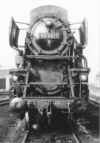 |
| Left: No 50-4011 from the front: 1959
This member of the series was converted to oil-firing. The access door for the preheater is under the main boiler.
Ebel-G�nsfu� p115
|
 |
| GREAT BRITAIN
Class-9
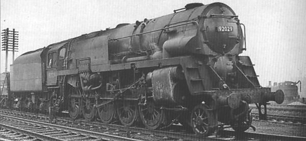
Left: A British Class-9 2-10-0 modified to Franco-Crosti form: 1955.
The preheater is under the main boiler, the British loading gauge not allowing side installation.
The circular preheater access door can be seen underneath the smokebox door.
See the cross-section at top of this page.
|
The standard Class-9's were highly regarded and considered to be the most thermally efficient steam locomotives ever to operate in Britain. The last ever British steam loco- the "Evening Star"- was of this type. Numbers 92020-92029 were built with Franco-Crosti boilers, but the modification only improved them a little, and was considered not worth the effort, given that the end of steam in the UK was already in sight. The preheater sections were therefore removed leaving a single main boiler barrel smaller in diameter than those of the standard Class 9 locomotives.
 |
| IRELAND
No 653
Left: An Irish 2-6-0 modified to Franco-Crosti form. The tender is being loaded with turf (peat) by the conveyor belt at top left.
This little-known experimental locomotive represents one of the most obscure Franco-Crostis. It was based on the Italian F-C designs, with a preheater on each side.
The 1907 Coey locomotive was modified in 1951 by C�ras Iompair �ireann, (Irish National Railways) the group formed on nationalisation in 1945, which included the former Great Southern Railways company. The Irish railways had suffered severe coal shortages during WW2, and these recurred during the exceptionally severe winter of 1947. Experiments were therefore conducted in 1952-1954 on burning turf, (ie peat) fed by screw from an enlarged tender.
Note the absence of a chimney at the front.
|
The famous O V S Bulleid had resigned as CME of the Southern Region of British Railways in Sept 1949, and became CME of CIE. He is known to have been in touch with Locomotive A Vapore Franco, the Italian constructors, and it appears that a Franco-Crosti boiler was fitted to 356 at his instigation. Whether this was an attempt to do two experiments at once, or if the increased thermal efficiency was considered crucial to the turf-burning project, is currently obscure.
The design appears to have differed from your average Franco-Crosti in that exhaust steam as well as hot gas were used to warm the preheaters. The exhaust steam was then used to preheat the combustion air, the air heater being underneath the tender. At the moment, the exit path of the exhaust gas is rather obscure. On leaving the preheaters, it was ducted over the roof of the cab to the tender, possibly so that it could be ejected by a blastpipe fed from the exhaust steam leaving the air heater.
As originally built, the steaming was awful, and a forced-draught fan was later added, powered by a bus engine carried on a wagon behind the tender.
Above: The Irish Franco-Crosti and its vital parts. The locomotive as constructed differed somewhat from this drawing; for example there was originally no chimney at the front.
The key to this diagram has been lost, (no, not by me) so here is my interpretation:
APreheater. This worked at full boiler pressure with water passing from it through a non-return clack valve to the boiler. This prevented the preheater from boiling as it extracted heat from exhaust gases that were at lower temperature than the gases in the boiler tubes.
BExhaust gases from preheater to tender
CExhaust steam from preheater to tender.
DAir preheater. On leaving the feedwater preheater, the exhaust steam was intended to still retain enough heat to warm the air blown into the firebox.
EHot air pipe to grate
FGrate
GDraught fan
HI have no idea what this is.
IOr this.
JExhaust steam pipe from cylinders to preheater
KExhaust steam heat exchanger for preheater
LChimney?
MFront chimney for lighting-up purposes.
NFront chimney shut-off valve handle.
| | | | | | | | | | | | | | | | | | | | | | | | | | | |
Note that I have added items J, K, M and N to the original drawing.
 |
| Left: The latter days of 653, with modified preheaters and a front chimney added for lighting-up.
It can't be seen in this picture, but "Experimental Turf-Burning Locomotive" is painted on the side of the tender.
|
Following a visit to Italy, Bulleid altered the preheater design to use oval structures on each side. These were made of aluminium, and were not noted for their steam-tightness. Since they were supposed to contain hot water and not steam, this was presumably a reference to leaks of water that flashed to steam on encountering atmospheric pressure.
Originally a hot-water injector was fitted, but this proved difficult to operate and was replaced by a Weir pump. The main purpose of this locomotive was to prove the feasibility of burning turf, and evaluating the benefits of the Franco-Crosti system seems to have had a low priority compared to the struggles with the turf-burning aspect of the enterprise.
The turf-burning project continued with the construction of "Bulleid's Turfburner" based on the Leader he built for The Southern Railway in England, but was eventually abandoned as diesel locomotives took over.