Updated: 27 Jan 2015
New:
Bailey engine added


Bailey engine added
Water Engines: Page 3
|
Updated: 27 Jan 2015
Bailey engine added |
ARMSTRONG'S ROTARY WATER ENGINE
W G Armstrong was one of the great pioneers in hydraulics, though as we have seen he was by no means the first to build a water engine in Great Britain. He was a very keen fisherman, and while he was angling on the River Dee at Dentdale in the Pennines, he observed in action a waterwheel that supplied power to a marble quarry. Armstrong felt that much of the available power was wasted, and on returning to Newcastle, he designed a rotary hydraulic engine. This was before he set up his famous Elswick works, (in 1847) and so a prototype was built in 1838 at the High Bridge works of his friend Henry Watson. As is usually the case with rotary engines, it was not successful.
Armstrong then adopted side-by-side cylinders with reciprocating pistons.
 | Left: Armstrong's rotary hydraulic engine: 1838.
|
 | Left: Armstrong's rotary hydraulic engine animated.
It is clear that Armstrong was aiming at a positive-displacement engine that could make better use of high water pressure than a waterwheel. This was many years before the invention of the Pelton turbine. |
 | Left: Armstrong three-cylinder hydraulic engine: 1850
The drawing shows what appears to be a substantial flywheel; it is a question as to why this would be required with three cylinders to smooth out the torque. Note that the engine is much more compact than the earlier beam engines shown on previous pages. |
 | Left: A surviving Armstrong hydraulic engine at Newcastle-upon-Tyne Swing-Bridge.
|
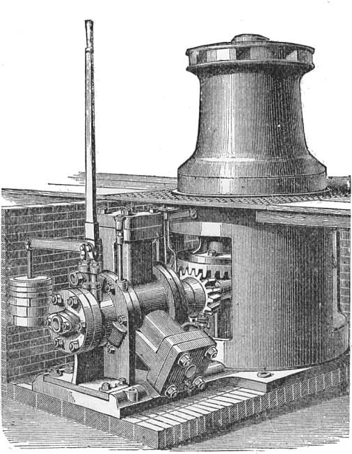
 | Left: A capstan powered by an Armstrong two-cylinder hydraulic engine.
|
 | Left: A cutting from Scientific American on Armstrong's introduction of hydraulics.
|
 | Left: A summary of one of Armstrong's patents.
|
When Armstrong established the famous Elswick Works on Tyneside, one of the first major orders was for several hydraulic engines, ordered by his friend Thomas Sopwith for the lead mine at Allenheads; they were used for pumping and line winding in the workings. This was at some point after 1845. Allenheads Heritage Centre now has one of the very few surviving Armstrong hydraulic engines; it was made at the Elswick works in 1852, and originally powered the saw mill at the Allenheads lead mine.
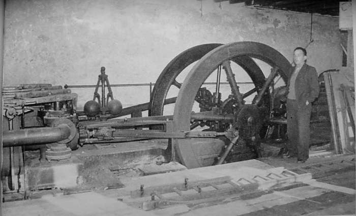 | Left: Hydraulic engine at Allenheads Lead mine on the Cumberland/Durham border.
|
In 1894, Armstrong's Elswick Works constructed and installed the steam-driven pumps, hydraulic accumulators, and hydraulic engines to operate London's Tower Bridge.
ARMSTRONG ENGINES AT SEA
Hydraulic engines were widely used on large ships, especially on naval vessels where it was necessary to rotate gun turrets weighing hundreds of tons. In naval language this is called "training" the turrets.
Sir William Armstrong, Mitchell & Co produced a single-crank double-acting engine that powered capstans with a pull of up to five tons. These had a fixed bedplate, avoiding the complications of the turn-over capstan system described above.
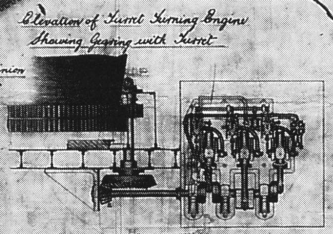 | Left: An elevation of a turret-training engine installed in HMS Inflexible.
HMS Inflexible was launched in 1876, and eventually scrapped in 1903. She had two gun turrets each weighing 750 tons in total; each turret carried two massive muzzle-loading guns weighing 81 tons each. Loading and ramming were also hydraulically powered. |
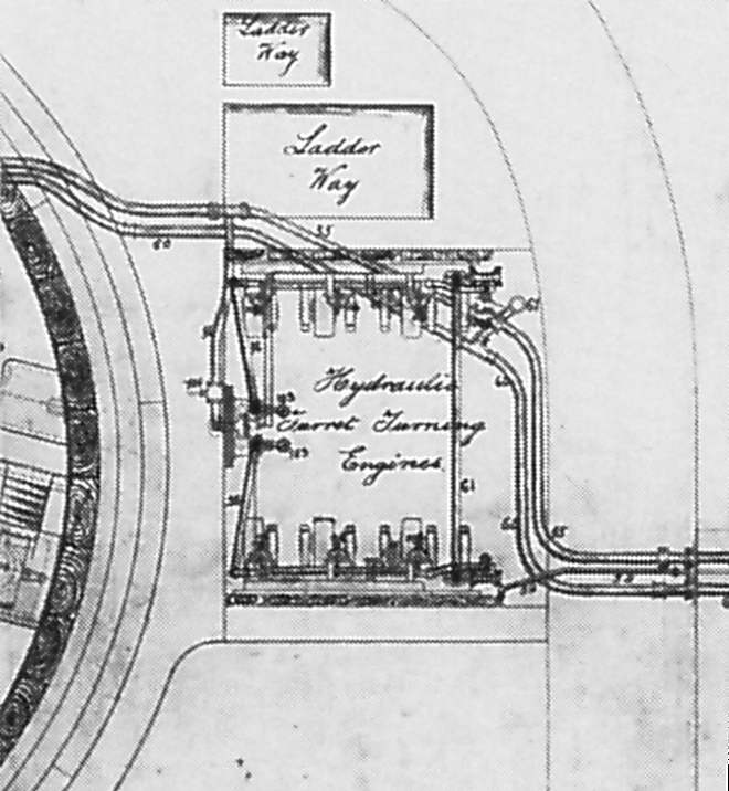 | Left: Plan of the turret-training engines in HMS Inflexible.
|
Some parts in the drawing above are numbered; this is how they are described on the original drawing:
 | Left: The Sinclair Engine.
|
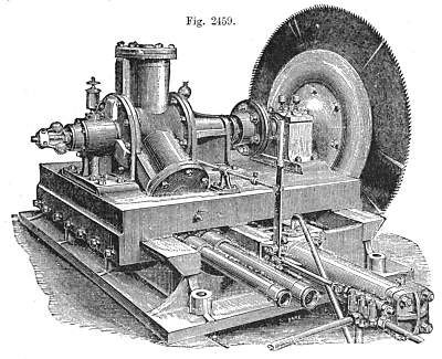
 | Left: A three-cylinder Ramsbottom engine
|
Mr Knight says "The Ramsbottom engine is largely used in England for operating printing-presses, circular saws, lathes, cranes etc."
 | Left: A two-cylinder Ramsbottom-type engine
|
The differences are such that it is a bit surprising that the model above is actually a Ramsbottom. For example, the trunnion and its valve-ports are in the middle of the cylinder rather than at the end, and there are conventional pistons rather than plungers. Nonetheless Knight clearly states it to be a Ramsbottom.
 | Left: A contemporary article about the Ramsbottom engine: 1865
|
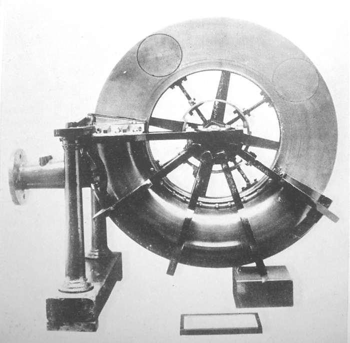
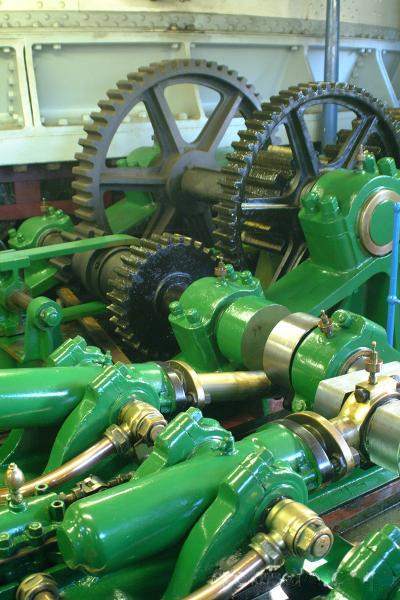
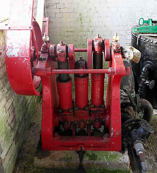 | Left: A three-cylinder Ramsbottom engine still in use at Twyford Waterworks
The head of water from Twyford Reservoir provides a pressure about 20 psi to drive the engines. |
![]()
ON RUNNING A WATER ENGINE
These instructions on how to run a Ramsbottom engine like that shown above were kindly provided by 'An anonymous operator'.
"One of the simplest and most efficient engines ever devised, and yet one which has had the least recognition, is the humble water engine. From its inception and development by such notables as Armstrong and Brotherhood in the nineteenth century, the water engine has continued to work with a minimum of fuss and attention. The water engine lacks all the glamour of the steam engine for it makes but little sound, and, due to its simplicity there it very little to go wrong or that which needs tinkering with.
When running it can be left alone for hours or days at a time with just the occasional visit to check on its oil and grease levels. Even an electric motor, which has the ability to shock, make noise and get warm, has more 'soul' than this engine - however, it would be quite difficult to be killed by a water engine.
At the start of the day, two minutes before you need the engine to start work, the operator needs to fill the bearing oilers and to refill the crankshaft grease cups. The main valve is opened and the engine will start to move. If the engine has been standing for a few days or longer, the leather cup washers, which seal the ends of the piston against the flow of water, will have dried out and will be leaking. With old, worn washers, this can be quite dramatic and a jet of water can be sent fifteen feet into the air, much to the discomfort of anyone who happens to be standing in the way. After a few revolutions, provided that the washers are not past their useful life, it then settles down: the only sound being the gentle and barely audible rush of water and the clunk of a worn bearing that requires a new shim.
Cylinder, valve and trunnion lubrication is by water and it is imperative that a little is allowed to leak from around the washers and at the point where the cylinders oscillate. When the engine is in mechanically perfect condition this should equate to a thin trickle of water from the front drain found at the bottom of the engine. This is the only water to be seen when the engine is running as both the inlet and the outflow are piped."
THE BROTHERHOOD WATER ENGINES
![]()
A highly successful range of radial water engines made in England.
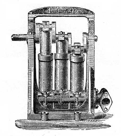
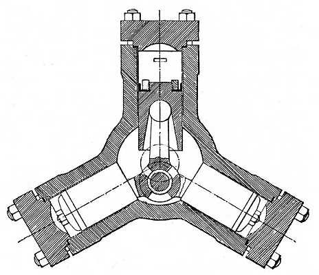 | Left: The Brotherhood radial engine: section
|
 | Left: The Brotherhood radial engine: another drawing
|
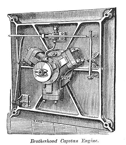 | Left: A typical application of The Brotherhood radial engine: driving a capstan. This is the underside of the mounting plate.
|
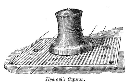 | Left: The capstan right way up
|
To underline that powered capstans are dangerous, in 1903 or thereabouts, an inquest was held on a 19-year old lad who got caught up in a rope being wound onto a hydraulic capstan at the Bishopsgate goods station (external link) in London, a facility that made extensive use of hydraulic capstans for moving wagons. The control pedals apparently jammed and the capstan continued rotating for something like a minute, with the unfortunates victim's head striking an iron stanchion once a second on each revolution; an experience he did not survive. I have to confess that I have mislaid the original source of the this story, and some of the details may be a little off, but the main story is correct. I will find it again one day.
 | Left: Another capstan driven by a Brotherhood engine
|
 | Left: Traversing saw powered by Brotherhood hydraulic engine (?)
|
The Brotherhood company is still very much alive:
http://www.peterbrotherhood.co.uk
 | Left: A Brotherhood engine with variable output
|
D is the rotary valve controlling water inlet and exhaust.
 | Left: A Hastie water engine at Wanlockhead
|
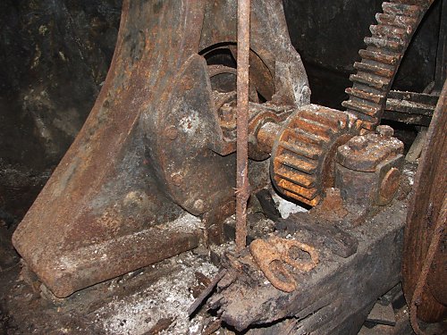 | Left: A Hastie water engine at Wanlockhead
|
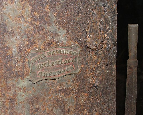 | Left: A Hastie water engine at Wanlockhead
|
THE HASTIE VARIABLE OUTPUT ENGINE
![]()
The Hastie variable output engine was a development of the Hastie engine shown just above, and resembles the Brotherhood-Hastie engine above in that a variable crank throw is automatically adjusted to alter the effective gear ratio. The output torque is sensed in the same way by means of heavy springs. The major difference is that the Hastie engine has oscillating cylinders, like the Ramsbottom engine, rather than the trunk pistons and connecting rods of the Brotherhood engines.
The advantage of the Hastie engine over the Rigg engine shown below is that it has fixed instead of rotating cylinders, eliminating movable pipe joints that are likely to be a source of leakage and extra maintenance.
 | Left: The Hastie variable output engine
|
 | Left: The Hastie variable output engine
|
 | Left: The Hastie engine torque sensor
|
 | Left: The Hastie variable output engine
|
When the Hastie engine was run from high-pressure mains with hydraulic accumulators, the springs were replaced by hydraulic rams, connected to the supply by a hole in the central shaft.
Here are some test results for a Hastie engine working a hoisr with a 22-foot lift, and running from a supply at 80 psi.
| Weight lifted (lbs) | Chain only | 427 | 633 | 745 | 857 | 989 | 1081 | 1193 |
| Water used (gall) | 7.5 | 10 | 14 | 16 | 17 | 20 | 21 | 22 |
This shows effective the Hastie principle was; without the variable output system, lifting just the hoist chain would have also consumed 22 gallons of water.
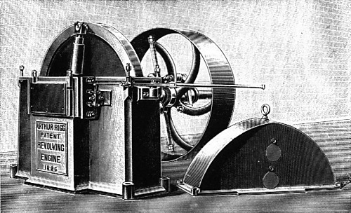 | Left: The Rigg variable-speed Engine. (Fig 3)
|
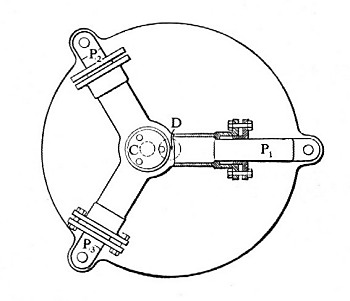 | Left: The principle of the Rigg variable-speed Engine. (Fig 4)
|
In small engines the movable centre C was moved by a screw and handwheel, but larger versions used a hydraulic servo in which a small control valve determined the position of a powerful stroke-control hydraulic ram fixed to C. This could be controlled by a governor to maintain a constant speed. This approach differs from the Brotherhood-Hastie engine which was governed by output torque and not output speed.
 | Left: Side elevation of a four-cylinder Rigg engine.
|
 | Left: Side elevation of the Rigg variable-speed Engine.
|
 | Left: Side elevation of the Rigg variable-speed Engine.
|
 | Left: Plan view of the Rigg variable-speed Engine.
|
Below is an edited extract from an article on hydraulic power in the 11th edition of Encyclopaedia Britannica (1911); the Rigg engine was clearly well-known at the time.
Direct-acting Water Motors.
"Owing to the difficulty of securing a durable motor with a simple and trustworthy means of automatically regulating the quantity of water used to the power needed at various times from the motor, not much advance has been recently made in the use of water motors with reciprocating rams or pistons. Probably the most successful one has been a rotary engine invented by Mr Arthur Rigg. In this engine the stroke, and therefore the amount of water used, can be varied either by hand or by a governor while it is running; the speed can also be varied, very high rates, as much as 600 revolutions a minute, being attainable without the question of shock or vibration becoming troublesome.
The cylinders are cast in one piece with a circular valve, and rotate about a main stud C (Fig 4), while their plungers are connected to a disk crank which rotates above the point D, which is the centre of the main crank; C-D being the crank length or half stroke of the engine, any variation in its length will vary the power of the engine and at the same time the quantity of water used. The movement of C is obtained by means of a relay engine, in which there are two rams of different diameters; a constant pressure is always acting on the smaller of these when the motor is at work, while the governor (or handpower if desired) admits or exhausts pressure water from the face of the other, and the movements to and fro thus given to the two rams alter the position of the stud C, and thus change the stroke of the plungers of the main engine. Fig 3 gives an outside view of a 30-HP engine capable of using water at a pressure of 700psi; the governor is carried within the driving pulley shown at the right-hand end, while the working revolving cylinders are carried inside the boxed-in flywheel at the left-hand end, the relay cylinder and its attachments being fixed to the bed-plate in front of the flywheel. On a test one of these engines gave an efficiency or duty of 80%."
The Rigg engine was also referred to in a paper by the eminent engineer H S Hele-Shaw, "Theory of a New Form of the Chamber Crank Chain" (Proceedings of the Royal Society of London. Series A, Containing Papers of a Mathematical and Physical Character, Vol. 87, No. 592 (Jul. 26, 1912), pp. 62-69.
Note that chain here refers to a kinematic "chain" not the physical thing you find on a bicycle)
You can read it here:
Proceedings of the Royal Society 1912.
According to a history of Chester: "Economic conditions remained difficult during the 1880s, and in 1889 Arthur Rigg's Victoria Engine Works failed." Since his engine was still being discussed in 1912, he presumably bounced back.
 | Left: Mr Arthur Rigg surfaces at a meeting of The Society of Engineers: 1901.
|
WATER ENGINE CUTTINGS FROM SCIENTIFIC AMERICAN
 | Left: Bad news for Mr S.B. of New York: 1856.
|
 | Left: A Water Engine in Stirling, Scotland: 1857.
|
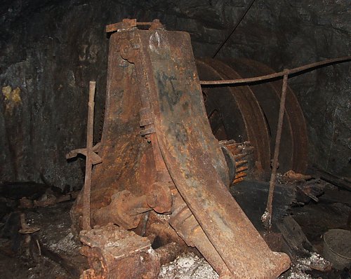
 | Left: A Water Engine down a British mine: 1857.
|
THE BAILEY ENGINE: 1880s
I saw this volume at a book fair, and I would have had to pay Ł50 to get that illustration. I didn't.
This engine is described in The Complete Textbook of Farm Engineering by Professor John Scott, published in 1885. There is an illustration of a small engine with a centrally-pivoted oscillating cylinder. which is geared up by about 2:1 to drive a small saw-bench (I think) by belt. A table is given of power output for different cylinder diameters, which indicate that Bailey made engines in a wide variety of sizes. An efficiency of 86% is claimed. Prof Scott says that the engine is in use in the stables of Sir Henry Hussey Vivian Bart, MP for Swansea, an appeal to water-engine snobbery if I ever heard one. It wasn't hard to track down Sir Henry, who was an industrialist and just the man to adopt a new techology- though water engines were not exactly new in 1885.
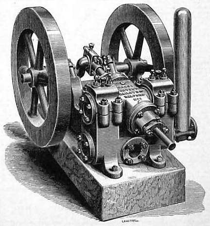 | Left: Bailey Water Engine: 1881
|
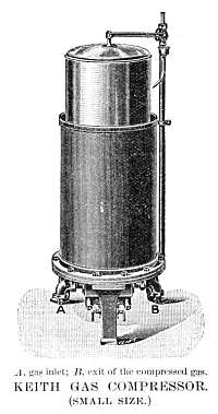 | Left: The Keith water-powered compressor, small size: 1900.
|
By 1912 Keith had apparently joined forces with a Mr Blackman, and James Keith and Blackman Co Ltd were still making water-powered petrol-air gas compressors used for domestic lighting purposes. A contemporary description reads: "...the pressure of the water actuates a ram attached through a stuffing-box to the compressing holder. The two ends of the ram are of different diameters so that the pressure on the larger ram overcomes that on the smaller ram, and the working is continuous so long as water is supplied."
The Keith and Blackman company still exists but is now a part of Woods Air Movement Ltd of Colchester; see here (external link)
The lighting of houses with a petrol-vapour/air mixture appears to have been a relatively short-lived business. If you lived in the English countryside around the 1900's, out of reach of mains gas and electricity, there were several options for lighting your house, none of them very alluring. Steam-engine-driven dynamos required a boiler which demanded constant attention from a competent and reliable (and therefore reasonably well-paid) employee; even then there was always the risk of an explosion. Oil lamps also required wick-trimming and refilling and were dangerous if knocked over.
The essence of the petrol-air approach was to have a gas producing plant that required minimal attention. To this end petrol-air gas plants were powered by:
![]()

|