This gallery of the Museum exhibits some unusual steam engines whose distinguishing feature is that the cylinder assembly rotates. They were originally on view in the Rotary Steam Engines gallery, but now have their own space here. The Knickerbocker engine does not have rotating cylinders and so has been moved to the Unusual Steam Engine Gallery, (in course of arrangement) which takes in all the engines that fit into no other category.
The designs in the first section (Kipp, Ruth et al) are taken from the book "Mechanical Movements, Devices and Appliances" by Gardner D Hiscox, published by Sampson Low, Marston & Co in 1899. For each design the title, and the parts of the captions that are in quotes, are taken from the original book; however, they are not 'rotary' engines in the Wankel sense. The source of the designs illustrated by Mr Hiscox is not stated, but the drawings look suspiciously similiar to those of engines in Knight's American Mechanical Dictionary, 1881 edition...
The Parsons Epicyclic Engine has rotating cylinders; it is important enough to have its own gallery/page.
These designs represent a kind of twilight world between normal reciprocating piston engines and rotary engines in the aircraft sense, ie where the cylinders are reciprocating but go round with the output shaft, while the crankshaft remains fixed.

THE TILL ENGINE: 1891
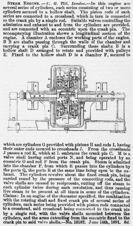 |
| Left: The Till Engine: 1891.
This is a description taken from a British patent, and there is no indication as to whether it was ever built or not.
Quite what advantage this engine was supposed to have over conventional ones is unclear. It is certainly compact, but then accessibility of the parts is awful. It is not clear from the description how the valves work, but since they are buried in the heart of the machine it looks as though varying the cut-off would be impossible.
Google is silent on Mr C G Till and his engine.
From "Industries" 11 Sept 1891
|
THE ATWOOD-PERKINS ENGINE
 |
| Left: The Atwood-Perkins Engine: 1894
This engine, by Lamotte Atwood and N W Perkins, which works on a sort of scotch-crank basis, does not actually have cylinders that rotate. However, it is so closely related in operation to the Kipp engine below that it has at least a temporary home here.
There are two sets of opposed cylinders at right angles, driving the crankpin 5. Steam enters through pipes 2 on each side, and 3 is the output shaft.
The Atwood-Perkins Engine is unknown to Google, so I think we can conclude that this idea did not thrive.
From US patent 514,054 date 6 Feb 1894, as published in and Railroad Journal 1894
|
 |
| Left: The Atwood-Perkins Engine: 1894
Another superb animation by Bill Todd. My grateful thanks!
Bill and I agree that the fixed ports- which are very inacessible- prevent any significant expansive use of steam. Bill also pointed out to me that the engine appears to be symmetrical so could start either way.
Just what the world was waiting for- an engine that may start in either direction at random!
|
 |
| Left: The Kipp Rotating Engine.
"A broad pulley enclosing four single-acting cylinders with opposite pistons connected by yoked rods. A fixed crank pin and slide block placed eccentric to the pulley axis gives the propelling force by displacing the pistons successively. The steam follows through ports in a disc valve with inlet and exhaust through the hollow shaft."
This design appears to use pistons of rectangular cross-section, presumably in the interests of compactness. It is unlikely that they as easy to seal as conventional cylindrical pistons. Note the use of Scotch yokes- sometimes called Scotch cranks.
From "Mechanical Movements, Devices and Appliances" by Gardner D Hiscox, published by Sampson Low, Marston & Co in 1899.
|
 |
| Left: The Kipp Rotating Engine.
This drawing also claims to show the Kipp engine, but it is rather different from that above. The text talks about yokes, but the drawing appears to show conventional connecting-rods between the double-piston assemblies and the central crank.
The two little circular drawings presumably depict the rotary valves. There is a handle at the extreme right of the bottom main drawing, and that may well have been to adjust the admission cut-off. Note the feedwater heater in the base.
I have to admire the ingenuity of making the engine its own flywheel and pulley.
Source unknown #6.
|
 |
| Left: Ruth's Rotating engine.
"A revolving cylinder engine. Three cylinders, A,A,A radiate from a shaft set eccentric to an outer circle or ring on which the piston-connected sheaves revolve. The pistons take steam through the ports M,M,M, just past the shortest eccentric radius, and drives out the piston during a half revolution, when the exhaust is opened and the piston is pushed back by the eccentric ring."
Hmmm. Not easy to see the point of this. If you wanted a compact and well-balanced steam engine, the Brotherhood three-cylinder radial would be a better bet.
From "Mechanical Movements, Devices and Appliances" by Gardner D Hiscox, published by Sampson Low, Marston & Co in 1899.
|
 |
| Left: The Almond Rotary engine.
"Four single-acting cylinders set tangent to a shaft which is central to an outer shell. The pistons have jointed segmental plates at their outer ends which press against the outer shell and cause the cylinders and shaft to revolve by the eccentric direction of their pressure. Disc ports for steam and exhaust."
Hmmm again. I am far from sure that pushing on a ring like this is an effective drive method. Even with rollers, I would have thought the pressure involved would have caused a lot of friction.
From "Mechanical Movements, Devices and Appliances" by Gardner D Hiscox, published by Sampson Low, Marston & Co in 1899.
|
 |
| Left: Coombers Rotating Cylinder engine.
"The cylinder rotates on trunnions with a through piston rod terminating with rollers running in an oval ring. Steam and exhaust ports in the trunnion. Pressure of the piston-rod rollers on the oval ring revolves the cylinder and fly-wheel on its trunnion."
This is Coomber's Rotary Engine from 1876, devised by Mr W A Coomber of Scotland Street, Ironworks, Birmingham, and described in "The Engineer" on Jan 21, 1876. This is one of the very few rotating-cylinder engines here that you can actually build! Castings etc are available from:
Brunell Models
From "Mechanical Movements, Devices and Appliances" by Gardner D Hiscox, published by Sampson Low, Marston & Co in 1899.
|
 |
| Left: A Rotary Multi-Cylinder engine. (Inventor unknown)
"Three or more cylinders are attached to and revolve with the fly-wheel. The crank is stationary and eccentric to the flywheel. Each cylinder is single-acting. Valves are on a central disc at A."
This is the basic principle of the rotary aircraft engine; the cylinders spin while the crankshaft stays stationary. Note the similarity to the Rigg Water Engine. What is the point here? Well, the weight of the cylinders is used to make up a flywheel, so I suppose you could argue that it saved on overall weight. On the other hand, there would need to be some complicated arrangements to get steam to and from the rotating cylinders.
From "Mechanical Movements, Devices and Appliances" by Gardner D Hiscox, published by Sampson Low, Marston & Co in 1899.
|
THE LJUNGSTRÖM "CRANKLESS" ENGINE: 1900
This engine is unusually well documented, by a detailed article that appeared in "English Mechanic" in 1900. I have reproduced the whole text below. Regrettably there are no engineering drawings in the article, but I have managed to find a sectional drawing from another source.
The inventor was Fredrik Ljungström of turbine fame. Charles Parsons came up with a comparable rotating-cylinder engine before he turned his mind to turbines; see The Parsons Epicyclic Engine. However, that was in 1877. This engine appeared almost a quarter of a century later, when Parsons' turbines were well-established, and are in fact referred to at the end of the text here.
This cannot be a case of starting with a rotating engine and then working up to turbines as the Ljungström turbine was patented by Birger Ljungström and Fredrik Ljungström in 1894. However, steam turbine technology does not necessarily render this engine obsolete, as its compactness and ability to reverse quickly could have made it useful in some industrial applications.
However, the Ljungström engine seems to have made little or no impact.
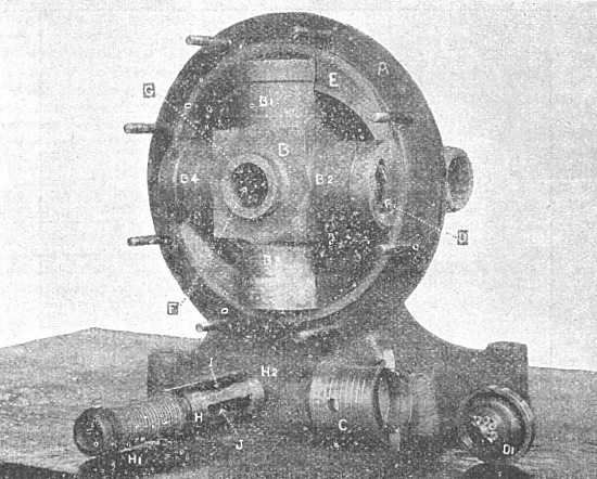 |
| Fig 1: The Ljungström engine: internals of a 15HP version.
The engine has four hollow cylindrical pistons moving in and out of the cross-shaped casting B as it rotates. Their slotted ends carry rollers D,D1 which bear on the inside of an elliptical track E. The central valve assembly carries inlet ports I and exhaust ports J, the exhaust being released into the steam-tight casing. Fuller details are given in the reproduced text.
Note that this is not quite the same as a four cylinder Coomber engine. The Coomber has the axis of cylinder rotation offset from the centre.
Apologies for poor image quality. I have done the best I can with them.
From "English Mechanic" 6 April 1900.
|
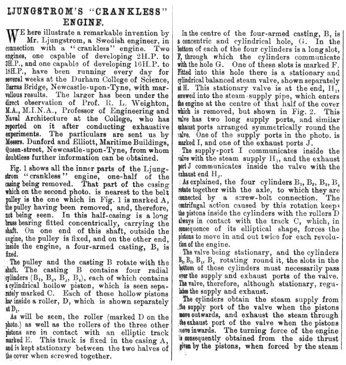 |
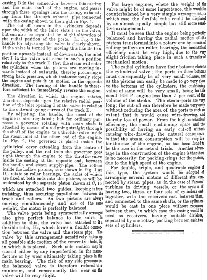
| Left: The first part of the text on the Ljungström engine.
Apologies for text distortion at the edges. The book is old and disintegrating and I did not want to bend it back too far.
Text continues after next two pictures.
From "English Mechanic" 6 April 1900.
|
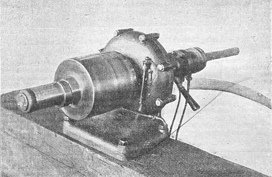 |
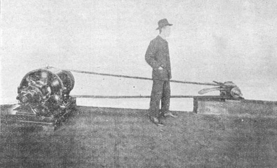
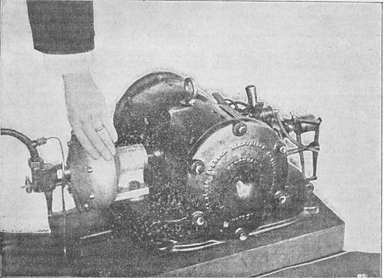
| Fig 2: The Ljungström engine: 16HP version on test, at the Durham College of Science, Newcastle.
Judging by the way the casings bolt together, this is a different design from the 15HP version pictured above. Why two different models of almost the same power should be built is a bit of a mystery.
The engine is set up here for belt-driving, with a pulley (immediately to the left of the bolted casing) almost as large as the engine. It was fitted with reversing arrangements (the handle to the right, which also controlled the cutoff) and a governor, hidden inside the cover extending to the left of the pulley. This controlled a throttle valve on the other side of the engine by means of a rod running through the centre of the engine. The purpose the two small pipes running out of sight is unknown, but it was probably lubrication.
From "English Mechanic" 6 April 1900.
|
The pipe on the axis of the shaft at right is the steam supply; it seems to start in mid-air because of the clumsy way the background has been erased. The larger pipe running out of picture to the right is the exhaust from the casing; the section nearest the engine also seems to have disappeared when the background was retouched out.
 |
|
Above: The internals of the Ljungström engine.
The elliptical track is here labelled 'C'. The pulley is to the left of the axial section and the governor is at the extreme right. The function of the part at extreme left is not clear, but it may be some sort of lubricator; the arrow-shaped thing running down the centre of the shaft is probably a drilled oil gallery.
From Norbye. This drawing is not part of the "English Mechanic" article.
|
 |
| Fig 3: The 16HP Ljungström engine driving a 100V 50A dynamo.
8 HP were required to drive the dynamo so the engine was only working at half-capacity. Shown with a man in a stylish hat to give the scale.
Careful with that belt, Eugene...
From "English Mechanic" 6 April 1900.
|
 |
| Left: The second and final part of the text on the Ljungström engine.
From "English Mechanic" 6 April 1900.
|
 |
| Left: The 16HP Ljungström engine.
It's that man again, giving the scale of the engine. Of course, it would help if we knew how big he was.
The exhaust pipe has disappeared altogether this time.
From "English Mechanic" 6 April 1900.
|
 |
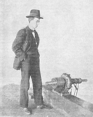
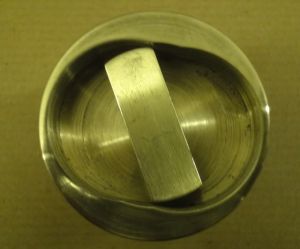
| Left: The 2HP version of the Ljungström engine.
Here driving a dynamo directly. The engine is the light-coloured thing under the hand- the rest is the dynamo. The article says that a 5HP version could be constructed to be the same size, which seems pretty impressive.
From "English Mechanic" 6 April 1900.
|
So, how well did it work? The reproduced text says that under test at Durham College of Science, Newcastle, two engines, one of 2HP and one of 16HP, had been running every day for several weeks "with marvellous results". On the other hand, I can find no other reference to the engine anywhere, which hardly indicates a commercial success.
I do not really feel qualified to comment on the rollers-pushing-at-an-ellipse concept, though I have my doubts about its mechanical efficiency. If any mechanical engineer can help with that, I should be very grateful. Otherwise, it all looks pretty sound- for a start, there are normal pistons which could easily be sealed with rings, avoiding all the debilitating difficulties of rotary steam engines. There is variable cut-off for expansive working. Looks quite a good scheme to me.
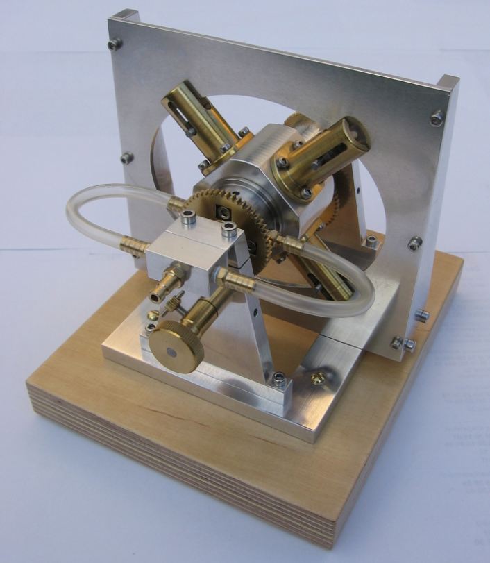 |
| Left: The Ljungström Engine modelled by Gerd Niephaus
Gerd Niephaus has been making model steam engines since 2007. He has made a superb model of the Ljungström engine; see it on his website here. There are many high-resolution pictures.
You can see the model running on compressed air on YouTube.
|
MODEL ROTATING-PISTON ENGINES
|
| Left: Ian Ralston Engine: 2010
This is a neat little rotating-piston engine made by Ian Ralston.
Actually, in this case the pistons (inside the rectangular bit) remain stationary while the outer rotor spins, making it a kind of inversion of the Ljungström engine. So far it has only been powered by compressed air.
Image by permission of Ian Ralston
|
|
| Left: Ian Ralston Engine: 2010
Drawing of the external rotor with ports for the air.
Image by permission of Ian Ralston
|
|
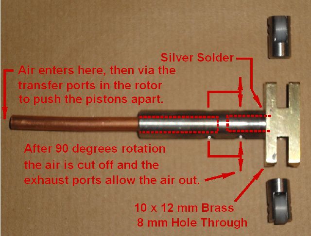
| Left: Ian Ralston Engine: 2010
Explaining the air path.
Note the Delrin rollers at the end of each piston.
Image by permission of Ian Ralston
|


