Updated: 21 Dec 2007
Mr Onion's wheel added


Steam Wheels. |
Updated: 21 Dec 2007 |
![]()
A steam wheel is a specialised kind of rotary steam engine arranged around the periphery of a circle, actuated by the weight of liquid that has been displaced by steam pressure or condenser vacuum.
The obvious disadvantage is that the maximum available torque is severely limited to the moment provided by the moving mass; this is much less than can be obtained by steam or vacuum acting on a piston. The speed will also be slow because of the high viscosity of liquids compared with gases.
 | Left: Amontons' Firewheel.
The chamber A is heated by the furnace; the air in it expands, passes through the sinuous pipe, and presses on the water in inner chamber a, which is pushed up into chamber b through a non-return flap. The weight of this water unbalances the wheel and causes it to rotate, bringing chamber B into the heating position. Rotation is anti-clockwise. |
W, at bottom right, is a cistern of cold water to cool down the air compartments The test-tube shaped arrangements are presumably intended to keep the air and water in their respective compartments as the wheel revolves.
The astute reader will have noted that Amontons' firewheel is not actually a steam engine- no water is boiled. It is actually a form of hot air engine. However it seems most fitting to exhibit it here with the other wheels.
It is not at present clear whether this wheel was ever built; "presented" may simply mean that Amontons read out a description of his design. While there seems no reason why it should not have rotated as planned, it seems most unlikely it could ever have done a useful job of work. The quantity of displaced water implied by the diagram would provide little torque, especially as it is near the centre of the wheel rather than the periphery. The heating of the air compartments would not have been very rapid and the speed of rotation would be correspondingly slow. The power output would have been very small.
 | Left: Watt's mercury-steam wheel as drawn in 1781.
|
Watt's first model was made of wood and 9 inches in diameter, was operated by blowing air into the steam inlet.
The wheel was worked on by Matthew Boulton and Dr William Small at Boulton's factory in Soho, Birmingham; at this period Watt was still based in Scotland. A Dr Roebuck was also involved, though on what basis is currently unclear.
In August 1772, Dr Roebuck told Boulton to order three barrels of mercury from Messrs Grote Son & Co which would weigh 561 pounds and cost 3s 10�d per pound, a total cost of �87. It could be resold at 3s 10d per pound when no longer needed. By September Boulton and Dr Small were ready for a trial; Roebuck thought that if the wheel was operated non-condensing, a steam pressure of 30 psi would be required; much more than was in common use with reciprocating engines. Apparently this trial never took place, as at this time Boulton lost money through the failure of the bankers Neale, Fordyce & Downe, ws obliged to spend a lot of time in London arranging matters.
The steam wheel was not a success. Watt worked on it sporadically until at least 1781, with some assistance from John Southern. When a Mr A Kemp enquired about Boulton & Watt�s progress with the steam wheel on the 5th December 1782 it appears that by then the idea had been completely abandoned.
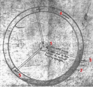
| Left: James Watt's mercury-steam wheel, annotated by the man himself.
Steam is admitted to three compartments in an annular wheel via the three radial spokes, controlled by ports at the hub. The pressure forces the mercury partly around the wheel, but there is an opposing force on the opposite end of the "cylinder" which makes the wheel rotate clockwise. This opposite end is actually a none-return valve that lets the mercury through as the wheel revolves. Watt claimed that three compartments were enough to give a steady turning motion.
This drawing is not of high quality, but I have included it here as it is annotated in Watt's own handwriting; this is not legible at this scale so I have added the numbers as a key.
|
1 "...steam from the boiler and into the hindmost..." Rest illegible.
2 "mercury"
3 "valve"
4 "vacuum"
5 "steam"
This scheme has the great advantage that all sealing problems are eliminated by the mercury. It also has one or two disadvantages...
Clearly the maximum torque is limited by the weight of the mercury used, acting on the lever arm of the spokes; you could add more mercury, but it is expensive stuff. The maximum speed is also limited by the rate at which the mercury will flow through the annular tube in order to keep its own level.
A more pressing reason why we may be thankful that these things did not become popular is that they would condemn everyone nearby to an agonising death, something that is always a drawback in a piece of machinery.
Mercury is a highly toxic material that attacks the nervous system and kidneys. It is eliminated from the body only slowly, and levels can build up until symptoms of temporary and permanent damage occur. Symptoms of chronic low-level exposure include: fine tremors, taste/smell changes, emotional disturbances, lack of concentration, headache, fatigue, weakness, lung disease, brain cancer and infertility. Some of these symptoms are easily confused with those of other diseases, making timely diagnosis uncertain.
The main great danger is inhalation of the vapour which comes off liquid mercury in hazardous amounts even at room temperature. (It has been plausibly argued that this caused the premature death of King Charles the Second, who was a keen amateur alchemist) When heated by steam the production of vapour would be much greater and the exhaust from this engine would surely have been highly dangerous.
At this period mercury was not recognised as poisonous; it was still being put in medicines.
 | Left: The drawing of Watt's wheel: 1769.
|
The dark section of the wheel is labelled "mercury or Newton's metal". Newton's fusible metal (named after Sir Isaac Newton) contains 50% bismuth, 31.25% lead and 18.75% tin; it melts between 91� and 95� C, so even low-pressure steam would have kept it molten. It would presumably have been a lot cheaper than mercury, and also a good deal less toxic, but it would have the disadvantage that it would solidify when the engine was stopped; quick starting on a cold morning would not have been one of its advantages.
 | Left: Moore's steam wheel; axial view.
|
The image above is taken from the original engraving in Stuart; note that the arrows on the steam inlet pipe h are drawn in the wrong direction, and so are the arrows a, which are presumably meant to show the direction of rotation.
This design appears to require a large sliding area between the inner wheel and the fixed casing to be sealed, preferably without too much friction, and this is its downfall. Stuart says "Mr Moore's idea is a very ingenious one; and could a mode be suggested of making the inner revolving drum steam-tight, without so great a loss of power as takes place in its present form, from the friction of so large a surface as the edges of his revolving cylinder, it appears capable of considerable precision in its action."
This passage seems to imply the engine was actually built.
Note that while this certainly a wheel, it is actuated directly by steam pressure and not by weight. Whether it belongs here or in the rotary steam engine gallery is a moot point.
The Moore wheel was originally described in the Repertory of Arts, Vol XL, p194, second series. I'm afraid I know nothing about this presumably English journal.
 | Mr Onion's wheel consisted of an annulus rotating around a hollow shaft. The method of operation was the same as that of Watt's engines shown above. The wheel was half-filled with a metal alloy that was liquid at the boiling point of water; 8 parts of bismuth, 5 parts of lead, and 1 part of mercury; a somewhat different alloy from that proposed by Watt, and from its mercury content, probably a more hazardous one.Mr Onions' fatal mistake was to fail to appreciate that this alloy expands considerably as it cools and solidifies. On the morning after its first trial run, the engine was found burst into pieces by the expansion of its liquid piston. The contemporary account at left is from The History and Progress of the Steam Engine by Elijah Galloway & Luke Hebert, London 1830, pp216-7. |
 |
 | Left: Masterman's steam wheel; axial view.
Stuart's description fails to make it clear how much of the motive power is provided by actual steam pressure and how much by condenser vacuum. |
 | Left: Masterman's steam wheel; transverse section.
|
 | Left: The valve arrangements of Masterman's steam wheel.
|
Stuart says that the Masterman wheel "...is similar to Mr Onions', but in everything relative to simplicity of construction, convenience of arrangement, and effective action, it is beyond comparison better adapted to practice."
This passage provided the clue that an Onions steam wheel remained to be discovered; and you can now see it on this page. This surely must be the same Mr Onion or Onions who attended a General Meeting of the Institute of Engineers on 26 July 1848 chaired by George Stephenson, where rotary steam engines were discussed.
 | Left: Ettrick's engine.
They billed it as "Another Rotary Engine" implying that editors were heartily sick of the topic as early as 1832. |
There are, of course,lots of snags. What stops the piston from knocking off the end of the cylinder when it smacks into it? Mr Ettrick has foreseen that question. "At first sight it would appear that the engine would be knocked to pieces by the violent motion of the heavy metallic piston, and the force with which it must strike the end-caps." Well, yes, that would seem to be the case.
Mr Ettrick's solution is to cut off the steam when the piston is half-way on its travel. It seems doubtful if this would help much; compressing some steam on the other side of the piston at the end of the stroke, by suitable adjustment of the exhaust timing would be more promising. However, the engine is of course still worthless.
Turn off the engine and the cylinder will come to rest in a vertical orientation with the piston at the bottom. Turning on the steam will simply push the piston up to the top without creating any turning moment whatever. To get the engine started you would need to give it a hefty push in the right direction. Mr Ettricks points out that this could be easily overcome by adding another cylinder at right-angles.
The only positive thing that can be said about this pointless engine is that the piston sealing problems would be much easier than for a rotary steam engine, being the same as a conventional reciprocating engine.
The Ettrick engine bears a haunting resemblance to this ill-conceived rotary Internal Combustion engine.
![]()
  
|