Rotary Steam Engines: Page 5.

Updated: 5 May 2009

The Root Rubber-Bag Engine added
Back to Home PageBack to The Museum EntranceBack to The Rotary Steam Engine Wing

CONTENTS OF THIS PAGE

SELECTED ROTARY ENGINES IN 1899:

The rotary designs in this section are taken from the book "Mechanical Movements, Devices and Appliances" by Gardner D Hiscox, published by Sampson Low, Marston & Co in 1899. For each design the title, and the parts of the captions that are in quotes, are taken from the original book. The source of the rotary engine designs used by Mr Hiscox is not stated, but the drawings look suspiciously similiar to those of rotary steam engines in Knight's American Mechanical Dictionary, 1881 edition...

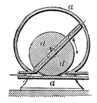
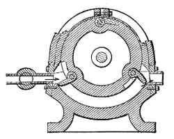
The Franchot Rotary Steam Engine
Left: The Franchot Rotary Engine.

"A slotted concentric cylinder carries a continuous solid wing across and in contact with the interior surface of an ovoid shell, shaped for exact diameter in all directions on the eccentric axis of revolution."

In 1900 Alotham and Franchot designed a vane compressor that looked exactly like the drawing on the left. There appears to have been considerable cross-fertilisation between rotary compressors and rotary engines; but a configuration that made a practical compressor was not necessarily a practical steam engine.

Once more the inlet and exhaust passages are both small and equal in size.

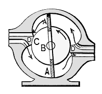
A Double-Slide Piston Rotary Engine
Left: A Double-Slide Piston Rotary Engine. (inventor unknown)

"In this engine the shaft and piston barrel are concentric, while the walls of the steam chambers are ovoid. A difficult form of construction."

Difficult indeed- it is hard to see how those sliding vanes are going to make it over the sharp projections at D.

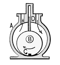
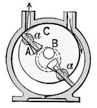
Rotary Engine (inventor unknown)
Left: Rotary Engine. (inventor unknown)

"B, shaft; C, eccentric inner cylinder; D, follower slide. The eccentric cylindrical piston operates the slide by its revolutions."

Another anonymous engine. Possibly based on the Yule engine of 1836


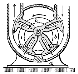
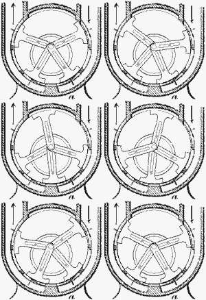
The Root Rubber Bag Engine
Left: The Root Rubber Bag Engine.

"A rubber lining loosely placed within the cylinder is rolled over by the three-armed roller spider."

It seems unlikely that the rubber bag would last very long under these conditions.

Gardner D Hiscox does not name the inventor of this engine in his book, but the drawing is now believed be of an engine patented by John B Root in 1856. (US patent 14778) It looks as if Hiscox combed the patent files for a long way back when he compiled his book in 1899

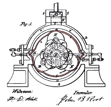
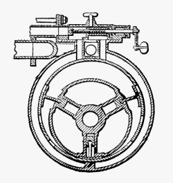
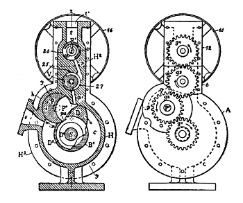
The Root Rubber Bag Engine
Left: The Root Rubber Bag Engine: patent drawing.

The rubber bag is here coloured pink.

If nothing else, this is a brave attempt to solve the sealing problems of rotary engines, but it seems unlikely that it would work for long, especially at the high speed that would be needed to make it a worthwhile engine for directly driving dynamos.

Note that this engine is actually rather more complicated than Hiscox's sketch implies. The three piston rollers are actually carried on friction rollers g',g' that permit the spacing of the piston rollers from the central axis to be varied. It is not clear from the patent what the purpose of this is, but it is probably to allow the pressure of the rollers on the rubber bag to be adjusted to get good sealing.

The box s,s on top of the casing is the steam chest; it contains a sliding valve that allows reversing by switching the inlet ports.

It is not a well-drafted patent. For example, the function of the horizontal sliding rods is not explained.


Boardman Rotary Engine
Left: The Boardman Rotary Engine.

"A cylinder revolving concentric with an outer segmental cylinder, with pockets containing swing pistons that open by centrifugal action at the steam inlet, making a steam abutment across the segment. The swing pistons are closed at the exhaust port by contact with the small segment of the outer cylinder."

Rotary Engine. (Inventor unknown)
Left: Rotary Engine. (Inventor unknown)

"...with concentric shaft and wing barrel. The two wing slides pass through cylindrical rockers to give the slides a slight oscillating motion; slides are kept extended by pins traversing a circular slot concentric with the shell."

The purpose of the slight oscillation is unclear.

Smith Rotary Engine
Left: The Smith Rotary Engine.

"Four arms with cylindrical sectors are rotated around an axis central to a perforated cylindrical shell. The driven shaft and head discs are eccentric to the shell. The pressure of steam between the wings tends to push them apart, by which the differential leverage on the disc pins 3 revolves the disc and shaft."

The sealing problems of this design would appear to be particularly severe; how is the end sealing supposed to work?

Smith Rotary Engine animation
Left: The Smith Rotary Engine.

This animation shows how it worked- if it did. The arms at the top are pushed apart by the steam pressure, exerting a turning force on the drum, which is mounted on an axis displaced from that of the arms.

Another brillaint animation kindly provided by Bill Todd

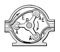
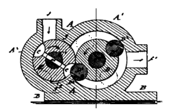
Berrenberg Rotary Engine
Left: The Berrenberg Rotary Engine.

"Two intersecting cylindrical shells. The steam cylinder D has two cylindrical pistons D',D' on opposite sides, that mesh in corresponding cavities in the cylindrical steam valve, both rotating in unison by equal external gearing. The steam port passes through the rotary valve E at the proper moment for the impulse. The supplementary sectors D2 are hinged to the pistons D1 to make a more perfect contact with the outer cylindrical shell."

At least this design has a larger exhaust port than the inlet port, even if not by much.

Fletcher's Rotary Condensing Engine
Left: Fletcher's Rotary Condensing Engine.

"A hollow drum on a shaft eccentric to a double shell. Three slots carry slides and socketed arms as abutment wings, which are kept in contact with the cylindrical shell by a ring not shown. Steam ports on inner shell at the left side. Exhaust ports on the inner shell at the right."

The sliding feet are pivoted on a part that slides in and out of the cylinder. Note the recesses in it that allow the feet to seat snugly therein at the closest approach to the outer wall. The sealing problems of this design look rather daunting.

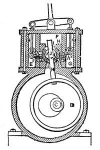
The Bartrum & Powell Rotary Engine
Left: The Bartrum & Powell Rotary Engine.

"A double shell divided for steam and exhaust. The inner shell cylindrical with a shaft and crank concentric. The crank pin carries a smaller winged cylinder, the wing sliding through a rocking joint. The end packing is made adjustable by a plate set up with screws. The crank pin has an eccentric sleeve which, by a slight rotation, compensates the wear of the rubbing surfaces."

This description gives a revealing glimpse of the sealing problems of rotary engines. Reciprocating engines did not need elaborate adjustable packing arrangements, nor did they have special features to take up wear, which was in this case presumably rapid.

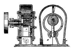
The Ritter Rotary Engine
Left: The Ritter Rotary Engine.

"A revolving cylinder concentric with the shell, carrying an abutting lip or extension fitting the outer case. A revolving lunette controlled by gear on main shaft allows the lip to pass; a continuous gear train operates the valve."

Or rather the valves, for there are two of them. Seems rather complicated.

The Forrester Rotary Engine
Left: The Forrester Rotary Engine.

"A cylindrical block and guard wing swing on an eccentric on the shaft. The guard wing slides in and operates the ports of a two-port rotary valve, the outer shell of which is operated by levers and connecting rods for reversing the engine."

There are plenty of potential sealing problems here, the greatest probably being the reliance on a line contact between the central block and the outer casing.

The story of the Rotary Steam Engine continues on Page 6 of this gallery.

Back to Home PageBack to The Museum EntranceBack to The Rotary Steam Engine WingTop of this page