Unusual Fans.

Gallery opened: 27 June 2026

Updated: 10 Sept 2026

Jost Hot-air Engine Fans updated here

Index added 26 Aug 2026
CONTENTS OF THIS PAGE
Back to Home PageBack to The Museum

A STEAM-POWERED FAN? NO, AN ELECTRIC FAN

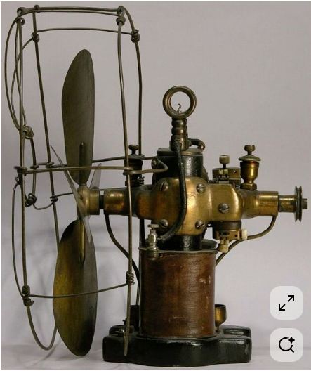
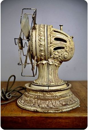
Left: An oddly constructed electric fan: date unknown

This image is about on the internet, where it is usually described as a steam-powered fan, with an inverted cylinder in the round thing at the bottom. I have my doubts.

Firstly, the whole idea of a steam-powered fan seems counter-productive because steam engines are hot, and rear of the fan will be drawing air over it. Having said that, hot-air engine fans were certainly produced.

Secondly, there are no pipes for steam supply and exhaust visible.

Thirdly, what looks very like an electrical cable runs from the round thingy (?) on top to a screw terminal on the rim of the round object at the bottom. I think it's actually an oddly-constructed electric fan.

Note the rather less than adequate fan guard and the small pulley at the right for driving other machinery, such as a sewing-machine.

Note also that big steam-powered fans were used to force air into the boiler rooms of ships, powered at first by reciprocating stean engines, and then steam turbines.


A STEAM-POWERED FAN? NO, A HOT-AIR ENGINE FAN

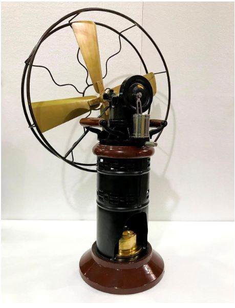
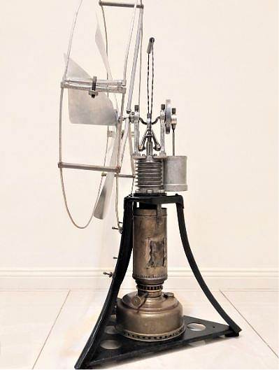
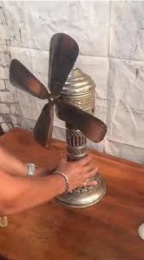
Left: A hot-air engine fan: date unknown

Having convinced ourselves that steam-powered table fans are an unlikely concept, we are confronted by this machine, which is for sale on Amazon and Ebay. Confusingly, both say it is a steam fan, but also say it is electrically powered. Both statements are wrong.

It does look very much like a steam engine, and at least one picture shows it with the burner at the bottom alight.

There is a plate on the front saying 'East India Company 1845' but it looks modern, and I am not convinced this really an antique. It is entirely possible that the East India Company was involved in making fans as Englishmen found India hot.

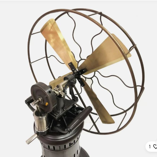
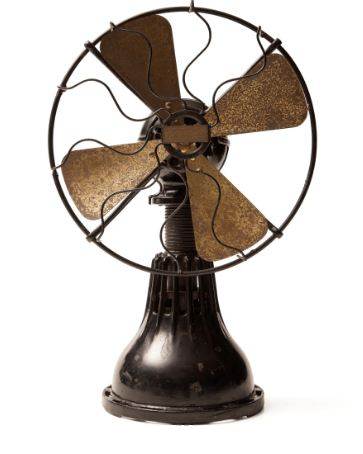
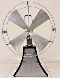
Left: A hot-air engine fan: date unknown

This top view of the fan shows there are two cylinders coupled to the crankshaft, one central, and he other perched on the edge of the main body. It looks as if the central cylinder is of much greater diameter than the other, and that made me think this is really a hot-air engine fan. The small cylinder is the power cylinder, and the big cylinder is the displacer, working in a Stirling cycle.

The problem remains that you are generating heat to get a cooling breeze.

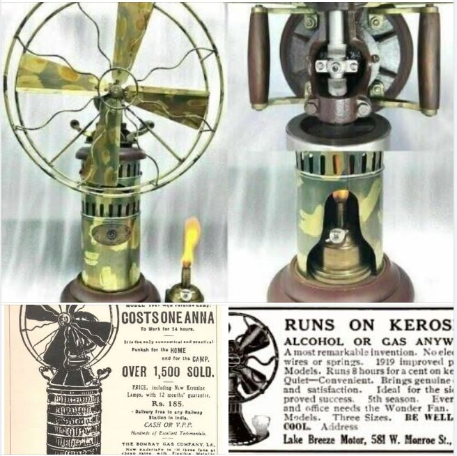
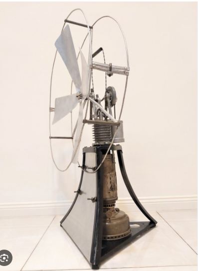
Left: A hot-air engine fan: date unknown

I think these old adverts clinch the matter. The one on the bottom left has the distinctive carrying handles seen above.

The ad on the bottom right is for a different design of hot-air fan. The Lake Breeze Motor Company were making them in 1919. It may be "A most remarkable invention" but it was not their invention.

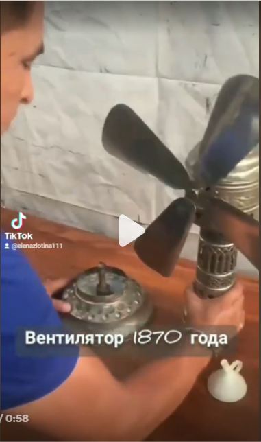
You can see a video of an East India fan running here. It is very clearly a hot-air engine.


THE LAKE BREEZE HOT-AIR ENGINE FAN

Left: A Lake Breeze Hot-Air engine fan: 1915-21

The only other hot-air engine fan currently known is the Lake Breeze fan, manufactured from 1915 to 1921 by the Lake Breese Moto company of Chicago, Illinois. USA. (there are various dates given on the Net)

Just below the bottom of the fan guard small vertical fins can be seen around the stem; these were to help cool the cold end of the displacer cylinder. They don't have much surface area and cannot have been very effective.

Hot air engines don't start by themselves. A small knob on the back of the fan was given a twist to start it once the internals had heated up.

Two levers near the base release the fuel tank and wick burner which lies under the base. A copper plate behind the blades states:

"Important directions use best grade alcohol only, grain or denatured, NOT wood alcohol. oil with one drop only, too much oil will stop motor, keep cap over wick when not in use and renew wick each 5 days" A wick only lasts 5 days? That sounds less than convenient.

You can see a video of a Lake Breeze fan here. The fan starts running at about 1:15.

There is some more info here.

This fan seems especially subject to misinformation, probably because few people know how a hot-air engine works. One web page said the fan was driven by a gas turbine...

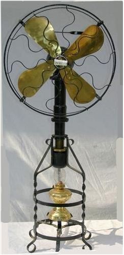
Left: A Lake Breeze Hot-Air engine fan: 1915-21

This is a different model of the Lake Breeze fan, on a stand.

The burner seems to be an ordinary oil/alcohol lamp with a glass chimney. Presumably the displacer cylinder is inside the black cylinder at the bottom.

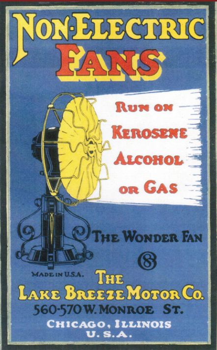
Left: A Lake Breeze Hot-Air engine fan: 1915-21

An advert for the Lake Breeze fan. The wonder fan!

This is the first time I have seen it suggested that these fans could be run off town gas. And why not?


UNKNOWN HOT-AIR ENGINE FAN

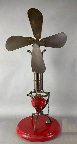
Left: Unknown Hot-Air Engine fan: date??

All I have is the picture; I think it's pretty clear it's a hot-air engine fan. Note the two carrying-handles near the top.

The brass thing on a chain resting on the base of the lamp looks to be a snuffer for extinguishing the burner.

Nothing else currently known.


THE JOST HOT-AIR ENGINE FANS

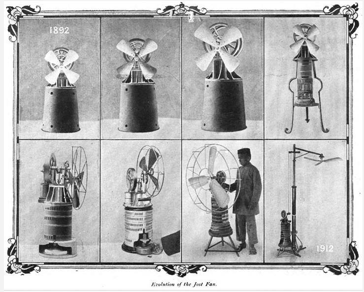
Left: The Evolution of the Jost Hot-Air Engine fan: 1892-1912

Carl Jost patented his hot-air engine ventilating fan in 1905. They were made by Hubertus Raab (1853-1922) in Zeitz, Saxony, in Germany. He also made parlour fountains; see below)

The final frame shows a Jost hot-air engine driving an overhead fan (presumably blowing downwards) via pulleys.

There is more info here.

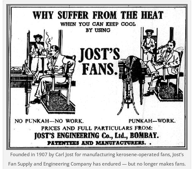
Left: The Jost Hot-Air Engine fan: 19??

A convincing exposition of the advantages of a Jost fan in business.

If you're not sure what a punkha is, ask the punkah wallah.

There is some more info here.

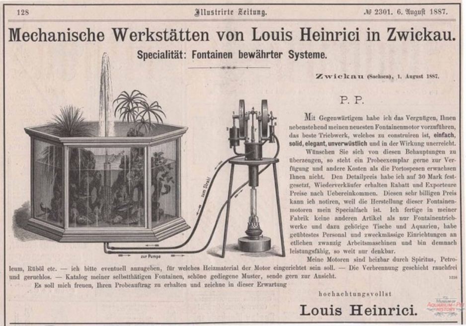
Left: The Jost Hot-Air Engine fan: 1887

One of Raab's early business partners was Louis Heinrici (1847-1930), an optician and master mechanic who started to manufacture small hot air engines in 1876, working in modest premises rented in Zwickau, Saxony,

Parlour fountains were a new thing to the Museum Staff. It was at one time fashionable to have a small fountain, often combined with an aquarium, in your parlour. The power required could easily be provided by a small hot-air engine, powered by gas or oil. Before electricity the only other source of power would have been a noisy steam engine, with its attendant issues of boiler explosions, and hence the need for skilled supervision.

This is another gamma-type hot ait engine, with the displacer in the centre, and the power cylinder on the left. The small cylinder on the right of the engine is the water pump.


THE STOVE-TOP HOT-AIR ENGINE FAN

Left: The Stove-Top Hot-Air Engine fan: date?? now

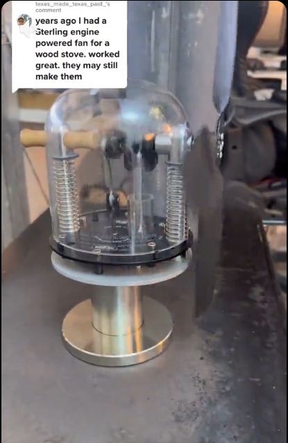
This is a stove-top Stirling engine made by the Warp5 company in the UK. A stove-top fan is driven by the heat of the stove it sits on; it is intended to move hot air around a room in winter.

Warp5 have a website here.

You can see a video of one of their fans running here.


THE BAILEY-LEE FAN

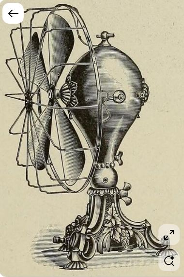
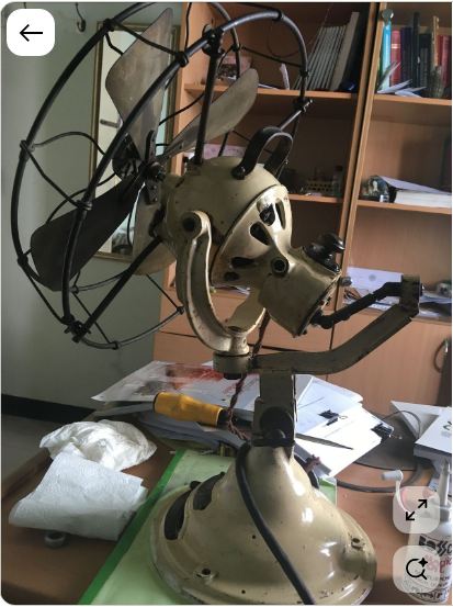
Left: The Bailey-Lee electric fan: date??

I can't help feeling that form is not following function here. The balloon-shaped casing does not seem optimal for an electric motor. I call this an Ugly Fan. (though not as ugly as this one. I am not a fan of it.

Note three possible control keys at top, lower middle, and bottom.


THE ENIGMATIC IONA FAN

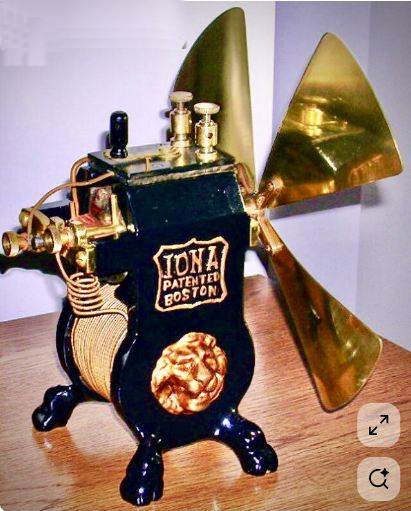
Left: The Iona electric fan: date 19??

There is little doubt about how this fan is powered. It looks like a very early electric fan.

Note the wholly exposed screw terminals on top. Clearly there is a big coil at the bottom, but it is unclear why the end should be sealed off with what looks like a mini-pizza.


THE MENOMINEE BANK TELLER FAN

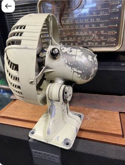
Left: The Menominee Bank Teller Fan: circa 1912

This is an electric radial fan, and I imagine it is supposed to blow horizontally in all directions; however the angle of the vanes doesn't seem right. It was marketed simply as a horizontal desk fan, and it is not currently clear why it became associated with bank tellers.

It was made by the Menominee Electric Manufacturing Company of Menominee, Michigan. This explains the odd name.

The cylinder containing the motor can be swivelled.


UNKNOWN RADIAL FAN

Left: Unknown radial fan: date??

It;s not quite clear what this radial fan (is that the right word) is supposed to do. It looks as though it might blow air upwards, which seems pointless. Was air supposed to come out horizontally in all directions?

The cable to the right suggests electric power.

All attempts to identify the maker of this fan have so far failed. Can anyone help?

Left: Unknown radial fan: date??

The same fan.


A CHAIN-DRIVEN OSCILLATING FAN

Left: A Chain-Driven Oscillating Fan: 1907-1912

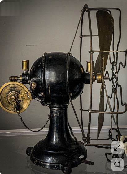
This fan was made around 1907-1912 by the Italian company Restelli, in Milan. It is electric, with a lever on/off switch on the side of the base at right.

The fan is moved to oscillate by a chain. A chain can of course only pull, and not push, so was there a spring involved somewhere? Apparently not, because other pictures show two chains, one each side of the brass wheel, and working in anti-phase. Note worm-drive to the brass gear wheel, and two lubricators. (the vertical brass cylinders)

You can see a video of the fan here, which shows clearly that there are two chains, one each side of the brass gearwheel.


TWO-AXIS OSCILLATING ELECTRIC FAN

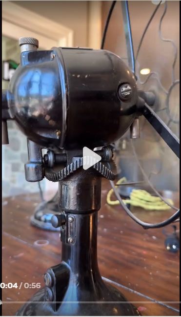
Left: A Two-axis oscillating electric fan: 19??

Oscillating fans that sweep from side to side in a horizontal plane are very common. I have such an electric fan (modern) sitting next to me now. However, the fan in the picture does not just sweep from side to side but rotates completely, and also nods up and down. To make continuous rotation possble there must be slip-rings to transfer the power to the motor. It was made by a company called American Electric.

At left there is a vertical enclosed shaft emerging fron the hemispherical motor casing, bearing a pinion that engages with the wavy gear track and rotates the fan. As it does so the two little wheels go around the undulating geared track to add a nodding motion to the fan. The brass knob at top left presumably turns on and off the oscillation feature.

Personally I find oscillating fans annoying and never use the feature. Not ever.

This a clear example of Gearwheels from Hell.

The picture is a still from a video. You can see a video of the fan working on YouTube.


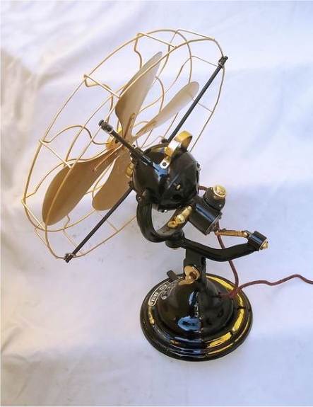
A VERY UGLY FAN

Left: A Very Ugly Fan: date??

As they say:"Degustibus non est disputandum" ie there is no point in arguing about people's tastes. But I assert this is one butt-ugly artefact; downright horrible. It looks like some sort of sneering monster. I am not a fan of it. The date of the patent on the casing is illegible.

There is a cable so it is an electric fan.

The brass knob at top right presumably turns on and off an oscillation feature.


A FOOT-POWERED FAN

Left: A Foot-Operated Fan: date??

If you don't want to use hot air engines, electric motors or clockwork, there is always the direct application of human muscle.

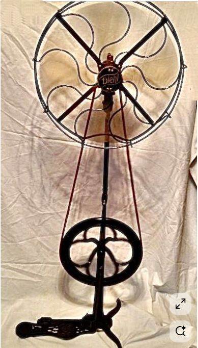
This is a Diehl foot-powered fan. The treadle on the floor drives the hefty fly wheel via a connecting rod (not visible against the fan column) and the rotation is speeded up by the small pulley on the fan shaft. Diehl also made electric fans.

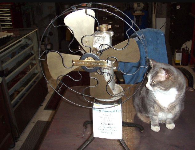
The electrically powered ceiling fan was invented in 1882 by Philip Diehl. Before this multiple ceiling fans were driven by water turbines in stores, restaurants, and offices; they were connected with belts. Some research needed here...
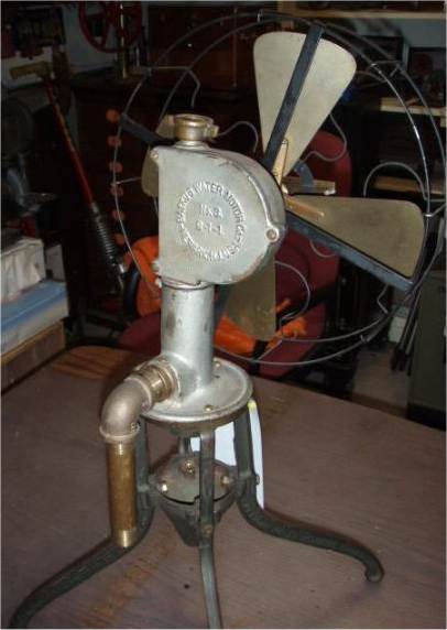
Man-operated fans have a long history, as any punkah wallah can tell you.

This fan at first seems absurd, because foot-pumping a fan is sort of counter-productive when you are trying to get cool. But of course in those days you could always get a devoted servant to do the footwork.


THE PAILLARD CLOCKWORK FAN

Left: A Paillard clockwork fan: 1910

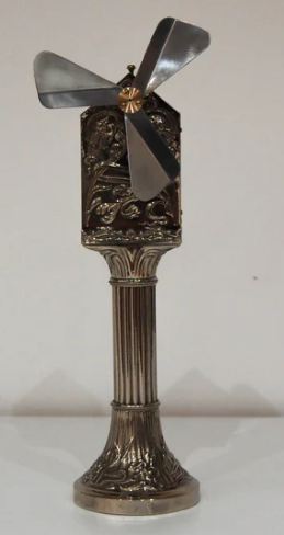
This is a clockwork-powered fan made by E. Paillard & Co. of Switzerland in the 1910s.

As soon as I saw this image I thought Clockwork! The winding handle is a dead giveaway, and the cylinder at the bottom no doubt holds a hefty spring motor. Another clue is the name Paillard; the company made a lot of clockwork gramophones and even some hot-air engine gramophones.

There are statements on the Net that it could run for 30 minutes per winding, but the general opinion seems to be that is very optimistic.

There is no fan guard; keeping a full set of fingers was your responsibility. An obvious problem is that you could get hot and sweaty winding it up; but given the date you'd probably have a servant to do it.

You can see a video of the Paillard fan being wound and then run here.
The casing is opened, and while it's not very clear, the spring appears to be geared up to fan speed in two stages of gearing.

It is clearly a Clockpunk artefact.


THE ZEPHYR CLOCKWORK FAN

Left: A Zephyr clockwork fan: 1902

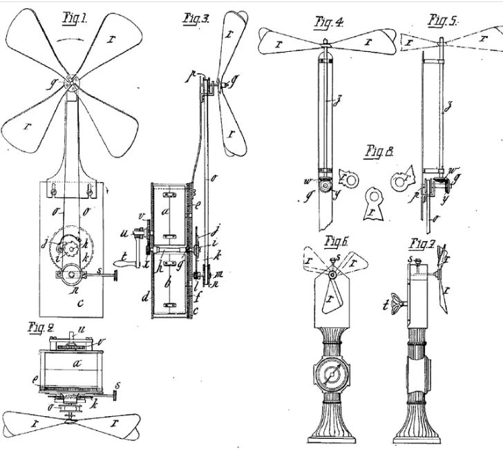
This floor-standing clockwork fan was made by the Zephyr Company of Paris. A US patent number 322,961 was taken out by Gabriel Kaiser in 1902.

The spring was wound not by a crank-handle like the Paillard fan, but by a giant key, which must have been rather awkward. When fully wound it would run ro 14 minutes before it ground to a halt.

Neither this fan or the clockwork Pailard fan just above appear to have any governor to control the fan speed, while spring gramophones always had such a device, as keeping the speed constant was vital. The clockwork fans presumably controlled their speed approximately because the power required to turn the fan increased rapidly with speed, probably as a square-law. In clocks a small fan (called a 'fly' in this application) was used to control the speed of the striking train.

There is more info here.

Left: A Zephyr clockwork fan: 1902

These diagrams are believed to be from US patent number 322,961, but the arrangement differs somewhat from the photograph above.

Turning the handle t winds up a sizable spring via two gears, that apparently gear up the handle rotation, perhaps for faster winding. The spring shaft carries a pair of gears j, k that speed up the rotation. The fan is then driven by a belt.


A SPHERICAL CLOCKWORK FAN

Left: A Spherical Clockwork Fan: date??

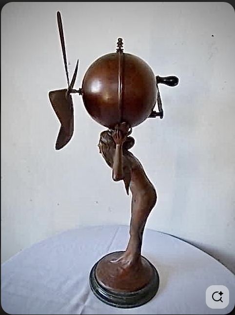
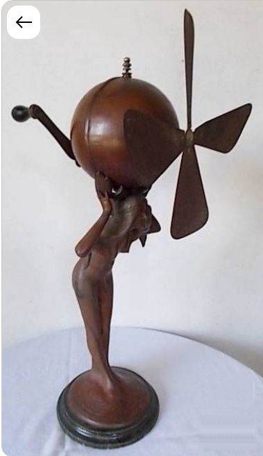
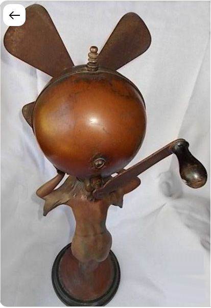
The hefty handle on the back of this fan gives a clear hint that it is powered by clockwork.

The sphere containing the spring is supported by an unclothed lady. To wind the fan you presumably clasped the lady around the waist with one hand, and cranked the handle with the other. Umm...
The little knob on top of the spherical housing is probably a stop/start control. Once again, no fan guard.
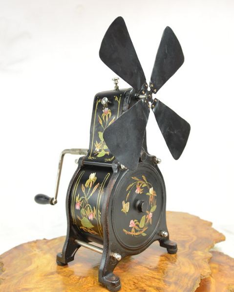
Manufacturer and date currently unknown.

Back to Home PageBack to The Museum EntranceTop of this page