Now and again, in the very early history of motor cars and aeroplanes, you will encounter references to a "carbonic acid motor", usually quickly followed by a statement that the machine in which it was installed was a total failure. Information on this method of deploying power is very hard to come by, but here are a few gleanings.
Carbonic acid is an old name for carbon dioxide. A carbonic acid motor (or engine) is driven by pressure which may simply come from a reservoir of compressed gas, or be produced by evaporating liquified carbon dioxide. A liquified gas takes up much less space than its compressed gaseous equivalent, giving the possibility of greater energy storage. Carbon dioxide is easily liquified, unlike the so-called "permanent" gases such as nitrogen and oxygen, which require more energy and more complex machinery to liquify, and are much harder to store for any length of time.
All gases have a critical temperature; below this temperature, the gas can be liquefied by the application of pressure alone. Carbon dioxide has a critical temperature of 31.1 °C, and so can usually be liquefied just by compression. The critical temperatures of oxygen and nitrogen are -118°C and -146°C respectively, and they are therefore much harder to liquify, as considerable pre-cooling is needed as well as compression.
Calling carbon dioxide "carbonic acid" is an obsolete usage. Nowadays carbonic acid refers to H2CO3, a weak dibasic acid formed when carbon dioxide dissolves in water; this acid exists only in solution.
THE EARLY HISTORY OF CARBONIC ACID
The history of CO2 engines begins early in the 1800's, when experimenter first liquified and solidified carbon dioxide. They discovered- sometimes through catastrophic explosions- that if CO2 was chemically generated in a sealed vessel, enormous pressures were generated. Using CO2 to replace steam in engines started to look promising. It was not.
THE BRUNEL GAZ ENGINE: 1823-1833
 |
| Left: The Brunel engine: 1823-33
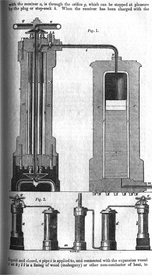
In the construction of an engine with carbonic acid gas for the motive-power, Marc Brunel, assisted by his son Isambard in the period 1828-33, spent nearly fifteen years and Ł15,000 in experiments on an engine driven by 'gaz' which is French for gas, and meant carbonic dioxide. Marc Brunel was a fellow of the Royal Society, and in spring 1823 he had heard Faraday speaking on the liquefaction of gases, especially carbon dioxide. A relatively small amount of heat would turn the liquid back into gas, and in a closed cylinder enormous pressures could be developed.
The passage below is taken from L T C Rolt's book on Isambard Brunel. I certainly can't hope to improve on Mr Rolt's prose style, so I hope this comes under fair usage:
"Put simply, the scheme was to generate gas from carbonate of ammonia and sulphuric acid and pass it into two surface condensers which were alternately heated and cooled and which communicated through expansion vessels and valves with a power cylinder. When the gas in one condenser was held in its condensed state by passing cold water through the condenser tubes and the the other was heated but the circulation of hot water, the difference in pressure between the two vessels was thirty-five atmospheres. This was the power which Brunel endeavoured to harness and which he believed at the time might supercede the power of steam
so promising did the idea seem that the experiments were heavily subsidised, even the Admiralty making a grant."
"The technical problems which had to be solved in order to translate theory into practice were immense and that they were solved is extraordinary when we think of the very limited metallurgical knowledge at that time. The gas condensed at a pressure of no less than 300 atmospheres, while pipes and pipe joints had to be made to withstand pressures of 1500 lbs per square inch. This in an age when, in steam engineering, 50 lbs per square inch was often considered dangerously high. Cast iron was obviously useless and a type of gunmetal was eventually evolved for the pressure vessels. Marc Brunel, just after the closure of the tunnel at Rotherhide (under the Thames, first attempt) spent six months working with an assistant named Withers. Brunel's notes and sketches suggest an apparatus just about as safe as a ticking time-bomb, and the most remarkable thing is that he and Withers failed to blow themselves up! At long last, however, Brunel was forced to admit defeat. On January 30th 1833 he wrote "Gaz - After a number of experiments I fear we must come to the conclusion that (with carbonic acid at least) no sufficient advantage on the score of economy of fuel can be obtained over steam power""
|
The image at left shows at the bottom a central double-acting power cylinder f; at extreme left and right are the apparatuses a and b for heating and cooling the carbonic acid. The cylinders c and d contained wooden pistons floating on oil, and it appears that the idea was that the gas pressure would transmit its force through the oil, keeping carbonic acid (which as the name suggests, is corrosive when wet) out of the power cylinder. Detail of its operation are proving hard to come by, but the Museum staff are on the case.
Cylinder c is shown in section at the top of the picture; note the enormous thickness of metal used to contain the pressures involved.
Source: Isambard Kingdom Brunel by L T C Rolt, pub 1957, pp 41,42. Not everybody is impressed by this book; Adrian Vaughan raises a lot of questions about its accuracy, though none relating to the gaz engine; it should be said that Mr Vaughn has also written a book on Isambard Brunel.
|
THE CHEVERTON ENGINE: 1826
 |
| Left: The Cheverton engine: 1826
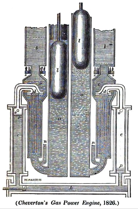
The Cheverton engine was supposed use either carbonic acid or nitrous oxide as a working fluid. The fluid was alternately vapourised by hot oil and condensed by cold-water, the fluid moving from one heat exchanger to another by displacer pistons, much as in a hot-air engine. This is the same princile as the Brunel gaz engine shown above.
a,a 'Refrigerators' filled with cold water
b, b 'Calorators' filled with hot oil
h The power cylinder
i The power piston
l,l Displacement plungers
n.n cold water inlets
The small size of the power cylinder compared with the rest of the machinery does not look promising.
I can find no evidence that the Cheverton engine was ever built. It is unknown to Google.
In the Mechanics Magazine text there is a passing reference to "Doctor Cartwright's much-neglected engine", which sounds like it might be interesting. It appears, that this refers to Edmund Cartwright, who was indeed a doctor (and a fellow of Magdalen college, Oxford) and made improvements in the sealing of pistons in steam-engines. His engine appears to have been an alcohol engine put forward in 1797, according to the 1911 Encyclopćdia Britannica.
Source: Mechanics Magazine 1826
|
AN ACCIDENT IN PARIS: 1840
One of the most famous carbonic-acid accidents occurred when Adrien Thilorier was experimenting with liquid CO2 in Paris. A cast-iron vessel exploded, and "tore off both legs from the unfortunate M Hervey."
The incident is mentioned by the famous chemist Justus Liebig in in a 1843 letter:
"...This, however, cannot be accomplished without considerable danger. A melancholy accident occurred at Paris, which will probably prevent for the future the formation of solid carbonic acid in these large quantities, and deprive the next generation of the gratification of witnessing these curious experiments. Just before the commencement of the lecture in the Laboratory of the Polytechnic School, an iron cylinder, two feet and a half long and one foot in diameter, in which carbonic acid had been developed for experiment before the class, burst, and its fragments were scattered about with the most tremendous force; it cut off both the legs of the assistant and killed him on the spot. This vessel, formed of the strongest cast-iron, and shaped like a cannon, had often been employed to exhibit experiments in the presence of the students. We can scarcely think, without shuddering, of the dreadful calamity such an explosion would have occasioned in a hall filled with spectators."
Wikipedia provides more details, though they do not quite line up with Liebig's account: "On 30 December 1840, Osmin Hervy, who prepared scientific demonstrations for lectures at the School of Pharmacy in Paris, was operating one of Thilorier's machines when the gas-generating cylinder exploded. Shrapnel broke Hervy's legs, one of which had to be amputated; he died of infection a few days later." Contemporary reports show that this is what actually happened.
MR BAGGS' CARBONIC ACID ENGINE: 1843
The Mechanic's Magazine carried an account of a lecture given by a Mr Baggs at the Cheltenham Literary and Philosophical Institute. He was said to have made "... ingenious and successful application of the expansive and condensable properties of carbonic acid, and ammoniacal gas to the production of motive power."
The account is disappointing. It gives no practical details of any engine, but does tell us that Mr Baggs knew little about his subject, because he denies that that carbonic acid cools when it is allowed to expand. He also makes light of the dangers involved in working with very high pressures. Baggs said that Isambard Brunel had told him personally there had never been the slightest accident during his gaz experiments.
"I put the question, the other day, to a friend of mine who has had very considerable experience in the liquefaction of the gases, whether he had ever had the slightest apprehension of encountering any accident in his numerous experiments. His reply was "Never! My apparatus is made of a proper strength, and to show my absolute conviction of its safety, if it were only well wrapped up in blankets, I should not have the slightest objection to take it to bed with me." No doubt there's website for that sort of thing.
|
Leaving aside any moral questions, this fellow, whoever he was, had poor grounds for his overconfidence. The Paris carbonic-acid accident had happened only a couple of years earlier.
No other evidence has been found that Mr Baggs ever built an engine.
Source: Mechanic's Magazine No 1021, 4 March 1843
THE LAY-HAIGHT TORPEDO: 1885
In 1884 or 85 the US Navy exhibited a Lay-Haight torpedo, powered by a reservoir of compressed carbonic acid that worked a Brotherhood engine connected to the screw. The torpedo was wire-guided and exploded from the shore, so was presumably intended for coastal defence only.
LILIENTHAL'S ORNITHOPTERS: 1893
The aviation pioneer Otto Lilienthal made many successful gliding flights before he was killed in a gliding accident on August 1896. He inspired the Wright brothers. Like several others before him, Lilienthal never quite abandoned the idea that flapping wings was the key to motion. In 1893 and again in 1896, he built gliders with flapping wings in the ornithopter fashion. Each machine had a lightweight carbonic acid engine that produced about two horsepower (1.5 kilowatts). The engine was supposed to make the wing tips flap up and down and move the aircraft forward. Neither model was successful.
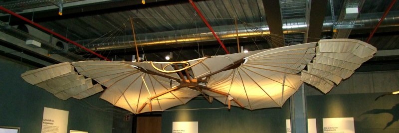 |
| Left: The Lilienthal glider: 1894
Lilienthal was also aiming for powered flight, on a flapping-wing basis. At the bottom of the glider there is a white cord holding two bell-cranks together; this cord was to be replaced with a carbon dioxide motor that would pull the wings down when it operated.
Photograph courtesy of Bernd Frieboese, Jan 2019
|
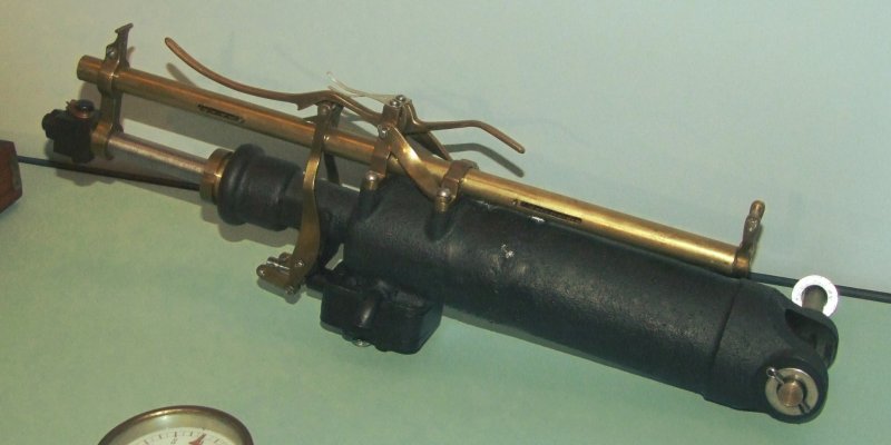 |
| Left: The Lilienthal carbon dioxide motor: 1894
Nothing is currently known of this engine beyond its outside appearance. Since the wings were connected to it by cords it presumably was a single-acting engine giving a pull action only. The black box at the bottom appears to contain the valves, which are apparently operated by the brass rod. The curved trigger on top appears to control the valves and so stop or start the engine.
Nothing is currently known of the operating pressure or the construction of the carbon dioxide reservoir.
Photograph courtesy of Bernd Frieboese, Jan 2019
|
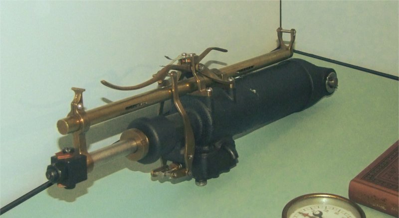 |
| Left: The Lilienthal carbon dioxide motor: 1894
There is a tantalising glimpse of a pressure gauge at lower right.
Photograph courtesy of Bernd Frieboese, Jan 2019
|
ARTHUR STENTZEL'S ORNITHOPTER: 1896
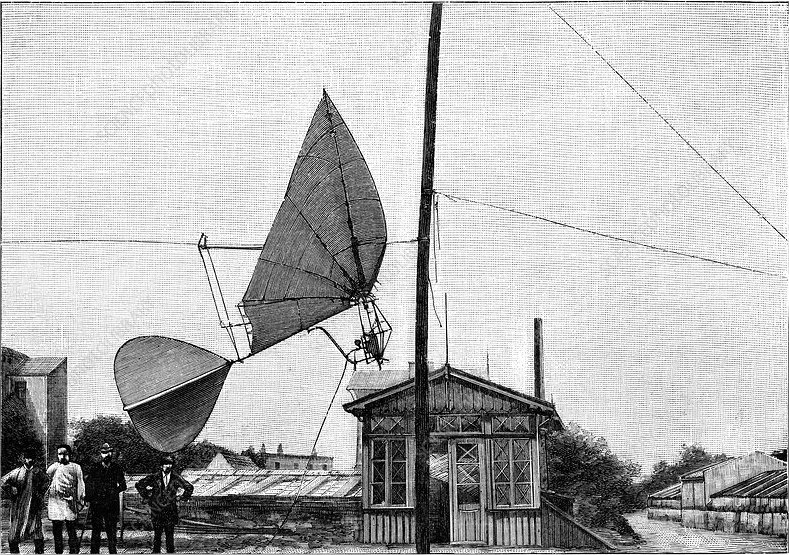 |
| Left: The Stentzel ornithopter with carbonic acid engine: 1896
Arthur Stentzel of Altona, Prussia, began experimenting with gliders and ornithopters at Berlin in the early 1890's. In 1896, he demonstrated a flapping wing flying machine. It had cambered bird-like wings with a 6.5 metres wingspan and a cruciform tail. It was powered by a carbonic acid engine mounted forward and below the wings. The flying machine ran along a horizontal wire, from which it lifted when in motion. The machine achieved a speed of 10 mph. The engine was claimed to give one horsepower.
This appears to be the only photograph in existence. Close examination shows what might be a V-twin engine but it is impossible to be sure. It looks as though the carbon dioxide was supplied from the ground through a flexible hose; there appears to be a round pressure gauge attached at the engine end of the hose.
A flying machine that cannot carry a carbon dioxide reservoir adequate for even (presumably) very short flights is not too impressive.
|
THE NEW POWER COMPANY CAR: 1899
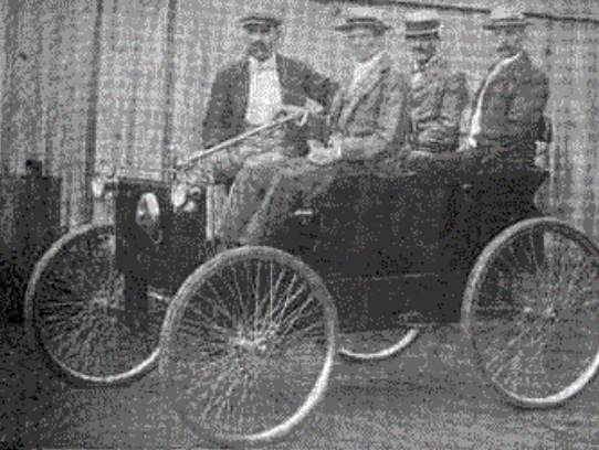 |
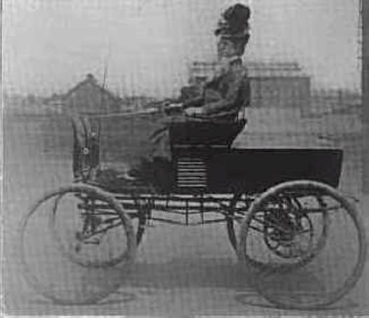
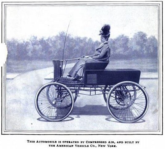
| Left: A carbonic-acid car by The New Power Company: 1899
The New Power Company was based in Trenton, New Jersey.
The following is extracted from The English Motor-Car Journal, 1899
"The carbon-dioxide is admitted to the engines under the full vapour tension of the liquid under normal temperature, the gas being heated to a high temperature before being admitted to the cylinders of the engines. One company is reported to have secured a factory at Kingston, N.Y., in which locality several very extensive cement factories are operated. The reputed cause for the selection of this centre as a site for the factory is that arrangements have been made with these cement companies for the gathering and storing of the carbon-dioxide generated during the burning of the cement."
A telling point there is the need to heat the CO2 before it could be applied effectively. Obviously some extra fuel would be needed for that, so the vehicle was not powered entirely by carbonic acid.
|
According to The Horseless Age, Oct 1898, the liquid CO2 was stored in the tubular frame of the New Power Company vehicle and heated to 90 degrees (Fahrenheit or Centigrade?) by a flame generated by "Sestalit" a patent solid fuel of the era. "The difficulty hitherto experienced with carbonic acid gas, when used for power, has been that the rapid evaporation would cause the valves to freeze. This difficulty the inventor claims to have overcome through a new valve which positively cuts off the current from the retaining cylinder at every stroke. One lever only is used for steering and regulating speed, while a second is required for reversing the motor."
"Sestalit" was a produced by the United States Fuel Company, who published a book on it called "The Marvelous Fuel, Sestalit" in 1890. They appear to have been primarily a coal mining company. The fuel was patented by Albrecht Pagenstecher in August 1890; see US patent 435,076. Sestalit consisted of hundred pounds of pulverized charcoal or coke, 3.5 pounds of saltpeter, (potassium nitrate) 3 pounds of starch, and 0.5 pounds of powdered brown sandstone, made into a paste with water and then pressed into moulds.
It was claimed that Sestalit could be lit with just a match, and then burnt "slowly and continuously without flame, smoke, or noxious gases and emitting an intense and uniform heat." It would still be a nuisance to have to light up the CO2 heater before setting off, but but a lot less trouble than the traditional paper, wood, and coal method of building a fire. Sestalit was intended for small-scale heating applications like sad-irons and foot-warmers.
THE GIBSON CARBONIC-ACID CAR: 1899
 |
| Left: The Gibson carbonic-acid car: 1899
A car powered by carbonic acid was developed by Charles Gibson of Jersey City, New Jersey. He was a well-known chemist and mechanical engineer. There is a chain drive to the rear axle, the engine being installed in the rear of the body.
The Gibson was powered by a horizontal two cylinder engine that developed 12 horsepower and weighed 32 pounds. Power was transmitted directly to the rear axle from a nine tooth sprocket of 1/4 inch pitch on the engine shaft to a thirty-nine tooth sprocket on the rear axle.
The carbonic acid was stored in commercial cylinders made by the Cooper Chemical Company of Newark, NJ. These cylinders were tested by Mr. Gibson to 6,000 psi and each had a capacity of ten to twelve pounds of carbonic acid. The ordinary working pressure of these cylinders was between 2,500 and 2,700 psi.
|
From The Horseless Age, May 31, 1899:
"The expansive power of carbonic acid is titanic, but two chief difficulties have stood in the way of its adoption for power purposes--the inability of inventors to control it and prevent the valves from freezing up owing to its too rapid expansion, and the high cost of the substance."
Gibson's car claimed to have eliminated the problem of freezing valves; this was clearly an endemic problem with the technology. The article thought that carbonic acid could be economically manufactured in quantity given enough demand for it.
It is not clear whether the freezing problem was caused by ice, originating from contamination with water, or if the carbon dioxide itself was freezing. This is entirely possible (and probably the more likely explanation) as solid carbon dioxide, otherwise known as dry ice, forms readily when liquid carbon dioxide is evaporated.
 |
| Left: The Gibson compressed-air car: 1900
This picture was on the front cover of Compressed Air and an article inside described the compressed-air car built by Charles Gibson.
The picture is clearly the same, but with the background altered; there's nothing new about fake news. Presumably Gibson simply charged the storage cylinders with air instead of carbonic acid and that was that. Why bother to take another photograph?
See more of this car on the compressed-air vehicle page.
Source: Compressed Air, Volume 4, Jan 1900, p829
|
SIGNALLING POWERED WITH CARBONIC ACID
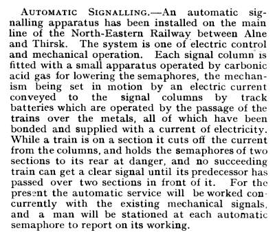 |
| Left: An article on railway signals powered by carbonic acid: 1904
An intriguing reference to carbonic acid, but with no real information at all. Was the gas piped to each signal, or carried there in bottles? Presumably it was in liquid form to increase the power storage density, otherwise they might just as well have used compressed air.
I have never heard of this system of signalling before- it cannot have made much impact.
From Model Engineer & Electrician for 26 May 1904, p489
|

TRAJAN VUIA'S MONOPLANE:1906
In 1906 the Romanian aeronautical experimenter Trajan Vuia was living in Paris and testing a small bat-like monoplane with a tractor propeller. The pilot sat well below the wing on a framework with a four-wheeled undercarriage. It was driven by a carbonic acid motor, of which no details have so far been found, except that it was of inadequate power. (A later monoplane was powered by 24hp Antoinette petrol engine) Some short hops from level ground were made, the longest being 24 metres. Proper flight was not realised, but the machines are considered to be the immediate ancestors of the monoplanes which appeared in Europe before World War 1.
THE CETONIA CARBON DIOXIDE ENGINE FOR AEROPLANE MODELS: 1911
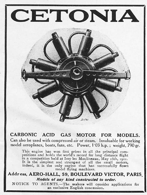 |
| Left: Cetonia carbonic acid engine for model aeroplanes
This sophisticated-looking 8-cylinder radial engine was advertised in 1911. Acccording to an article in Flight on 2 Septenber 1911, the engine could be supplied in either fixed (crankshaft rotates, cylinders stay still) or rotary (crankshaft stays still, cylinders rotate) format. The bore was 19mm and the stroke 28 mm. The crankshaft was mounted in ball-bearings. When officially tested at the Conservatoire des Arts et Metiers in Paris, it gave 1.03 horsepower at 1710 rpm for one minute, which seems a pretty hefty output for powering model planes.
The carbon dioxide was carried as a liquid in a steel cylinder containing about 1 kilogram, which underlines that it was meant to power rather large and heavy models. Worse still, it was necessary to carry on board a tank of hot water; the CO2 passed through coiled pipes in this to prevent it solidifying into "snow" on expansion, and choking everything up.
In this view it looks as though the supply pipes are being led straight into the top of the cylinders, but in fact the small cylinders they connect to are the tops of the valve chests. Nothing is known about the valve arrangements but from the shape of the valve-chests they were almost certainly of the piston type.
From Flight for 26 Aug 1911
|
 |
| Left: Inside the Cetonia engine
The eight connecting-rods appear to be connected to a ring around the crank-pin. The eight rods driving the valves are attached to a single eccentric on the crankshaft. The CO2 pipes are not shown, but were fed from a central manifold.
From Flight for 2 Sept 1911
|
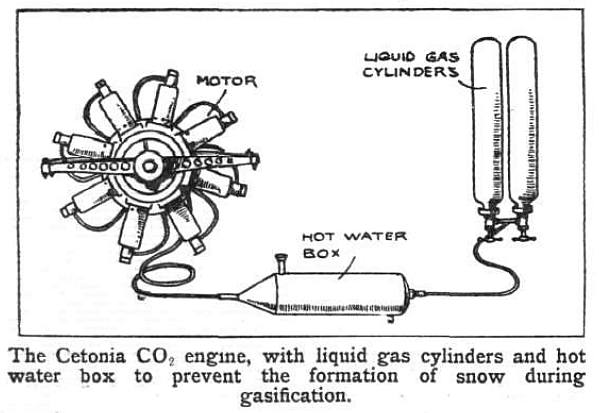 |
| Left: Cetonia heating system
Clearly this not going to be a light-weight power source.
Note the filler and drain plug on the hot water box.
From Flight for 2 Sept 1911
|
Further details are given in an article that appeared in Flight on 3 Feb 1912. The engine described above is the A -type, with an inclusive price in France of 225 Francs. Types B (1/2 hp) and C (1/4 hp) were crossed out in the French catalogue that Flight received, and so were presumably no longer offered. The temperature of the hot water was supposed to be 90 degC; presumably that was the starting temperature and it cooled rapidly in operation.
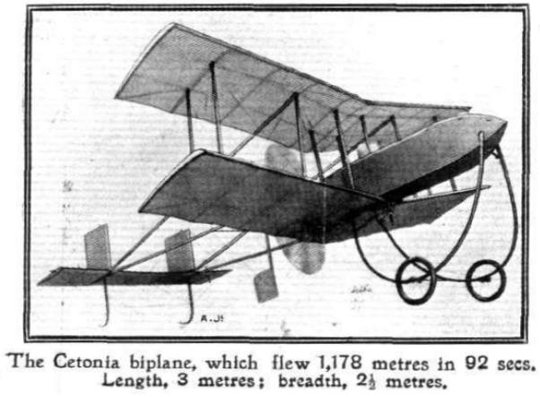 |
| Left: Model biplane with Cetonia engine
The model weighed a hefty 17.7 kg, of which 4 kg was the complete CO2 power-plant. It had a propellor 0.85 metre in diameter, and it flew at 29 mph. You wouldn't want to get in its way.
From Flight for 2 Sept 1911
|
The designer of the Cetonia engine was a Monsieur Poterin du Motel. That name raised an eyebrow; it is generally believed that Mademoiselle Stéphanie-Félicie Poterin du Motel was the woman over which the famous mathematician Evariste Galois fought the duel in which he was killed at the age of 20, in 1832.
Further searches for the name revealed H Poterin du Motel, the author of an 1899 textbook on life insurance, and perhaps more promisingly, a Jean Georges Marie Poterin Du Motel who took out British patent 147,656 for life-saving equipment in 1921.
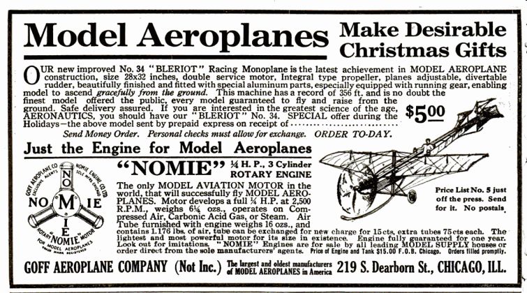
THE NOMIE CARBON DIOXIDE ENGINE FOR AEROPLANE MODELS: 1911
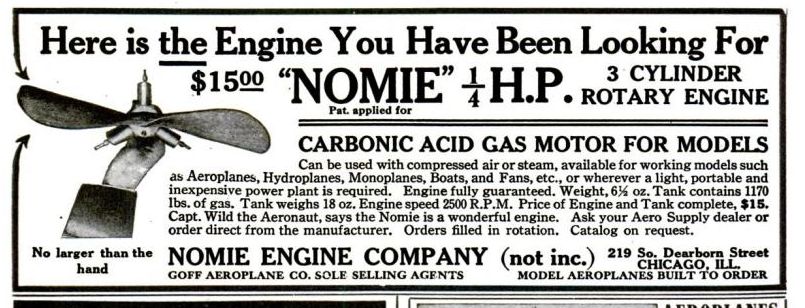 |
| Left: Nomie carbonic acid 3-cylinder rotary engine for model aeroplanes: 1911
The ad copy states that the engine has a 18-ounce tank, that somehow holds 1170 pounds (about half a ton) of CO2. I feel a decimal point may have gone astray- 1.17 pounds sounds a bit more like it. Note that it was supposed to also run on compressed air or steam.
I had grave doubts about the actual existence of "Captain Wild the aeronaut" but I was wrong. He was a well-known balloon-racing man, and you can read about his exploits in the Los Angeles Herald. (Volume 36, Number 47, 17 November 1908) The Nomie engine was less famous. It was advertised again in Popular Mechanics the next month, and again in May 1912, but then seems to have disappeared.
From Popular Mechanics November 1911
|
 |
| Left: Nomie carbonic acid 3-cylinder rotary engine for model aeroplanes: 1911
This ad appeared a month after the one above. The 'air' tank now is said to weight 16 ounces and to hold a more plausible if over-precise 1.176 pounds of gas. Arrangements for exchanging full and empty tanks are now available.
It is claimed the motor will also operate on compressed air or steam. In the latter case you presumably had to build your own boiler.
From Popular Mechanics December 1911
|
THE CARBON DIOXIDE POWERED LIFEBOAT: 1934
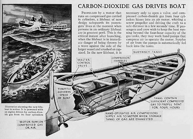 |
| Left: Carbon-dioxide powered lifeboat
My first thought was that this sounds like a frighteningly undependable means of life-saving. All those CO2 cylinders would have to be constantly checked for leaks and falls in pressure; was the ship supposed to carry around its own CO2 tanks for continuous topping-up? Having said that, modern life-rafts are often inflated by carbon dioxide or nitrogen cylinders, so perhaps it's not so daft after all. The system does not appear, however, to have ever been used for propulsion, so far as I can discover.
On the other hand, (so to speak) using manual power to compress air and keep the engine running sounds very questionable because of the high energy losses as heat when compressing a gas. The air might be hot when it entered the storage cylinder, but would soon cool down, and the heat energy would be lost.
From Popular Science for Feb 1934
|
The carbon-dioxide engine appears to be of the two-cylinder horizontally opposed type. One wonders if there were any provision for stopping it freezing up as the carbon-dioxide expanded; any water vapour in the CO2 would congeal and clog up everything disastrously.
CARBON DIOXIDE POWER FOR AEROPLANE MODELS: 1936
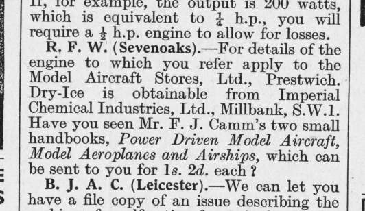 |
| Left: Advice on obtaining an engine and carbon dioxide for model aeroplanes: 1936
This advert appeared in Popular Mechanics for May 1936
|
THE IMP CARBON DIOXIDE/ACETYLENE ENGINES FOR MODELS: 1936
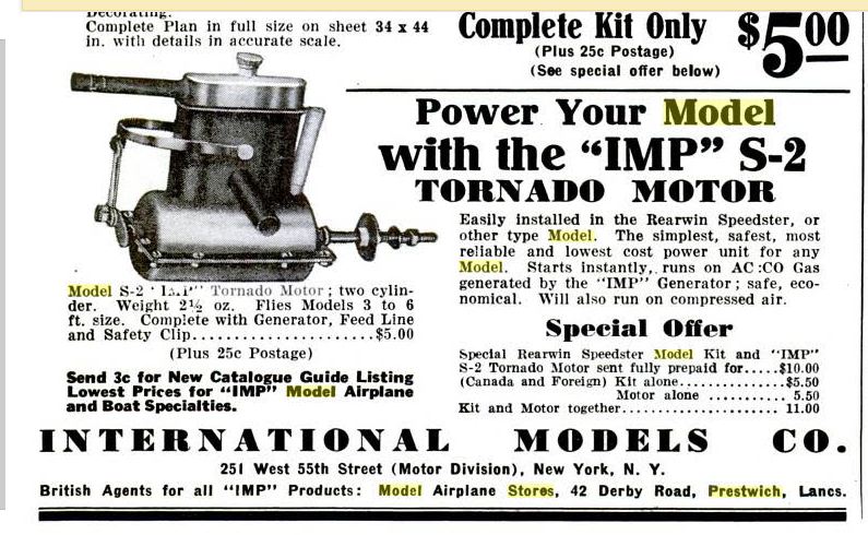 |
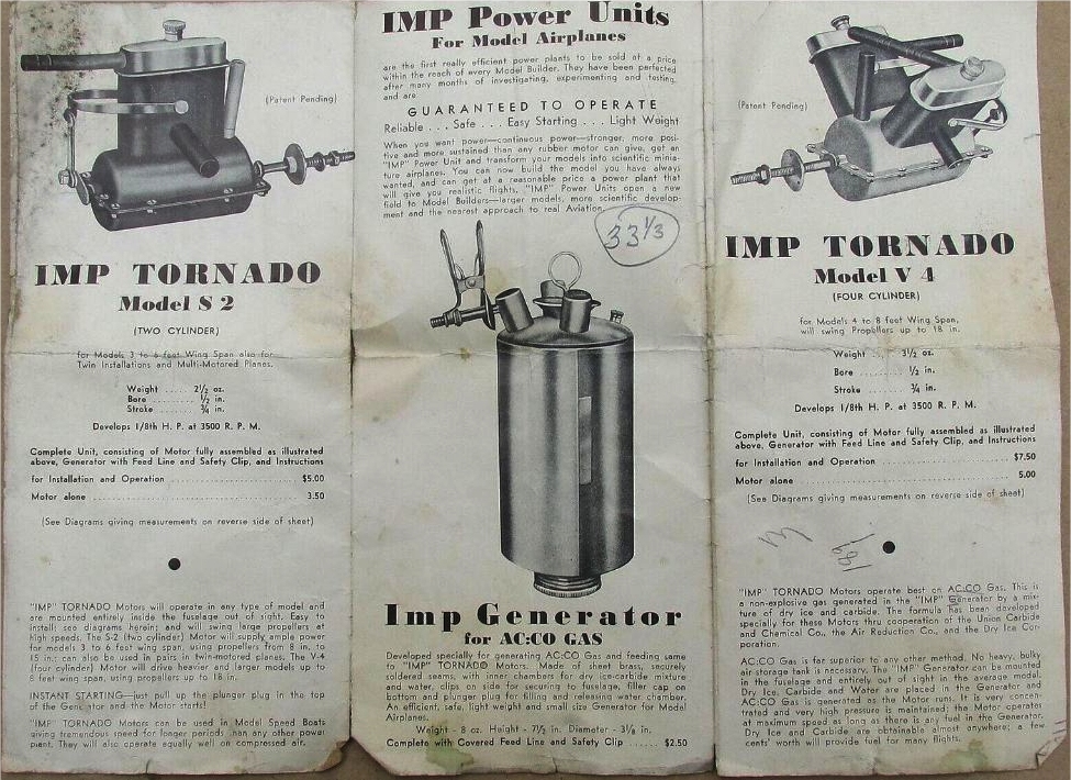
| Left: The IMP-S2 two cylinder engine: 1936
The makers claimed an output of 1/8 HP at 3500 rpm. The crank on the end drives the U-shaped lever which presumably operates an oscillating valve between the two cylinders.
Note that the British agents for this engine were the Model Aircraft Stores of Prestwich, mentioned in the Popular Mechanics advert shown above; presumably this was what they were supplying. Or were there other manufacturers whose engines they carried?
The 'Generator' flew with the plane, and contained a mixture of calcium carbide, dry ice, and water. The water reacted with the carbide to produce acetylene gas. This reaction is very exothermic and the heat evolved caused the dry ice to sublime into carbon dioxide. The text here refers to AC:CO gas, without explanation; fortunately they didn't mean carbon monoxide.
This advert appeared in Popular Aviation for November 1936
|
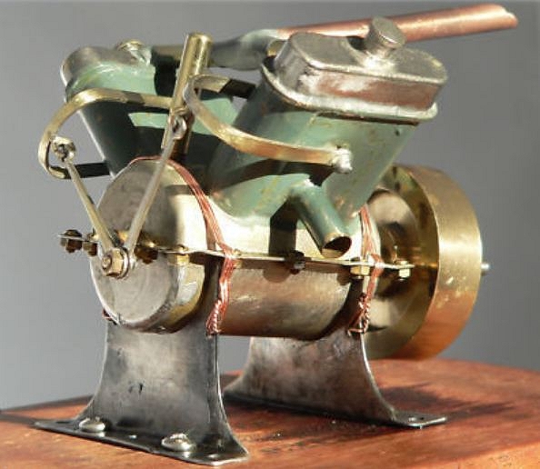 |
| Left: The IMP Tornado V4 engine: 1936
This is a V4 version of the engine; from the angle at which it is mounted it is intended to drive a model boat. Likewise the hefty flywheel would not be suitable for an aeroplane. The makers claimed an output of 1/8 HP at 3500 rpm, exactly the same as the S2 engine; something wrong there, I feel.
Each pair of cylinders has a stub exhaust coming out sideways, while the gas inlet is via the copper tube at the top, which is soldered to a horizontal pipe joining the tops of the cylinder pairs. The cubic capacity is 9.65cc; (0.589 cu in) The bore was 0.5 inches and the stroke 0.75 inches. The purpose of the round knob on top of each cylinder bank is currently unknown; for lubrication? The sloping brass tube at top left centre is described as the 'oil intake' in the instructions for the engine; presumably oil introduced here found its way to the crankshaft bearings.
Note the crude way the valve gear is coupled to the U-shaped levers. I don't think the valve timing can have been very precise.
IMP engines were made in Japan by a company called International Model Products. It appears to be unknown to Google.
|
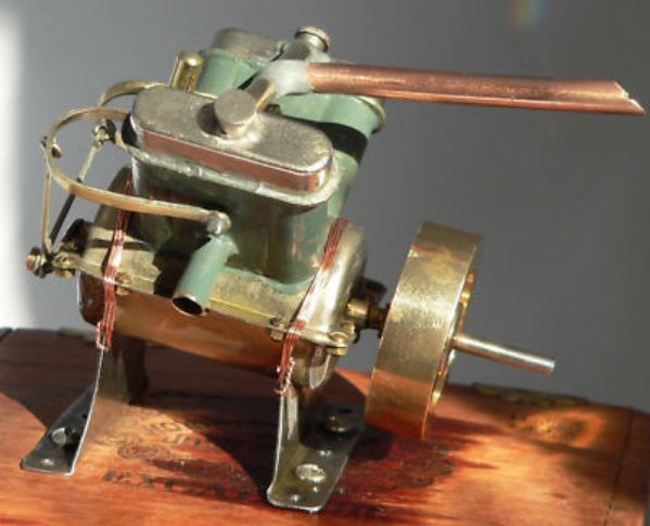 |
| Left: The IMP Tornado V4 engine: 1936
Another view of the IMP V4 engine.
|
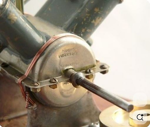 |
| Left: The IMP Tornado V4 engine: 1936
This is the end of the engine, with the output shaft; the flywheel has been removed from the shaft for the photograph. Note the name IMP TORNADO on the end of the crankcase.
|
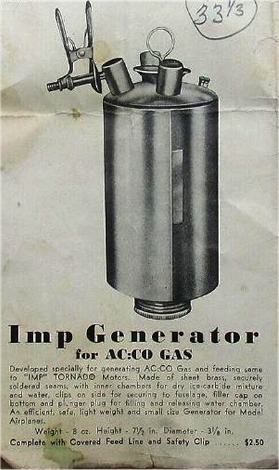 |
| Left: The IMP gas generator: 1936
Here is the IMP gas generator, and some info on what it actually does. The generator was carried by the plane or boat; there was no pressure vessel for gas storage.
The generator was charged with calcium carbide, dry ice, and water, so AC:CO gas was a mixture of acetylene and carbon dioxide, which was my first suspicion. Don't bother Googling it as you just get stuff about air-conditioning. The water reacted with the carbide to produce acetylene gas. This reaction is very exothermic and the heat evolved caused the dry ice to sublime into carbon dioxide. The carbide and dry ice was broken into small lumps and mixed together, and then placed in the generator.
This seems to be rather clever; the carbide not only vaporised the CO2 but added acetylene to increase the amount of gas generated.
|
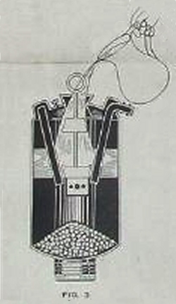 |
| Left: The IMP gas generator: 1936
Here the water is being added. Gas is not generated until you pull the ring on top, allowing water to reach the carbide and dry ice.
There seems to be no way to control the rate of reaction, as there is in a Kipp's apparatus. The instructions refer to a 'feed line and safety clip' which suggests that if subjected to excess pressure, hose and clip would be blown off the generator outlet.
|
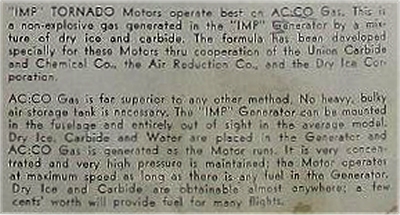 |
| Left: Notes on AC:CO gas from the IMP instruction sheet: 1936
Note that IMP claimed that AC:CO gas was 'non-explosive' which if true would seem to indicate the proportion of acetylene in the gas was low.
|
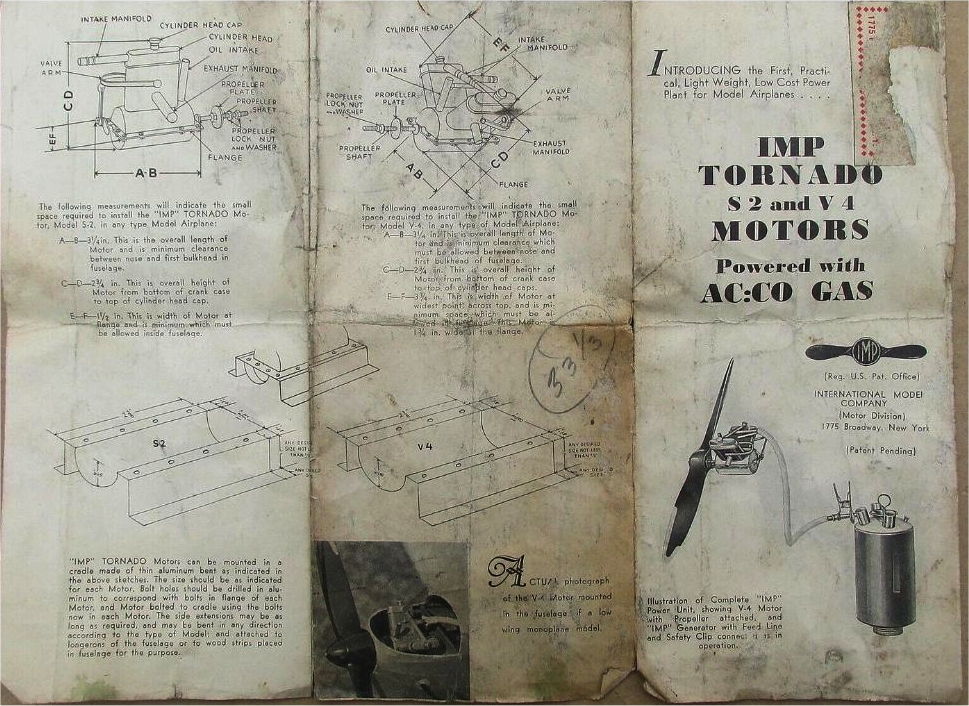 |
| Left: Notes from the IMP instruction sheet: 1936
|
 |
| Left: The reverse of the IMP instruction sheet: 1936
|
CARBONIC ACID MOTORS FOR AEROPLANE MODELS TODAY
This sort of motor must be quite obsolete, no? No. Certainly, typing "carbonic acid motor" or "carbonic dioxide motor" into a search engine will (at the time of writing) yield nothing. The result is quite different if you use "CO2 motor". You will find that modern carbonic dioxide motors are used to power model aeroplanes. Advantages include low noise output and no flammable fuel.
A small metal reservoir is charged with either liquid or gaseous carbon dioxide under pressure. This powers a motor that looks very much like a small glowplug engine. There is a valve at the top of the cylinder usually operated by a protrusion from the crown of the piston. Exhaust is via a uniflow port uncovered by the piston at the bottom of its stroke. Fins are provided, just as on a glowplug engine, but here the purpose is not cooling but heating, to stop the engine freezing up as the CO2 expands.
 |
| Left: Two CO2 motors for model aircraft
One pipe runs from a non-return filler valve to the reservoir, and the other takes the CO2 to the engine.
Image taken from the website of Davis Diesel Development. (with permission, I might add) See link below.
|
Here are some CO2 motor links:
www.gasparin.cz Do not miss the historical overview in the "CO2 motors" section.
www.davisdieseldevelopment.com
www.samsmodels.demon.co.uk/gasparin.html which shows some fine CO2 engines, including a V12!
SUPER=CRITICAL CARBON DIOXIDE FOR TURBINES
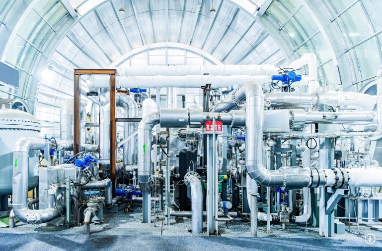 |
| Left: Supercritical CO2 turbine installation
Supercritical carbon dioxide is being introduced as a working fluid to drive turbo-alternators. When a fluid is under enough pressure and temperature so that the gas and liquid states cannot be disringuished, it is said to be supercritical. Supercritical CO2 is a one-phase system, avoiding the complications of a two-phase system like water and steam. The critical temperature for CO2 is 31 degC, and the critical pressure is 1,070 psi. (73 atmospheres) so the system operates under considerable pressure. Supercritical CO2 is often abbreviated to sCO2.
In steam turbines, entrained water droplets can cause turbine blade erosion. This cannot happen with Supercritical CO2 as there is only one phase. There are however still issues with blade life.
Supercritical CO2 is denser than steam and allows more compact turbines. Heat is transferred to the CO2 at a higher temperature than for steam, giving a higher Carnot efficiency; 50% cycle efficiency was achieved by General Electric in 2016; the full 10-megawatt turbine is the size of a desk. Steam cycle efficiency rarely exceeds 40%.
In China two 15-megawatt turbine power units have been connected to the grid. The heat comes from a steel works.
There is more information here, and here. The image comes from the first link, and I assume it is the relevant turbine installation in China, but this is unconfirmed.
|
There is a good deal more info in the journal Nature
Supercritical CO2 has a good Wikipedia page.
Supercritical CO2 is also used as an industrial solvent, for example removing the caffeine from coffee.
Many thanks to Bernd F for drawing this to my attention.