Gallery opened: 8 Feb 2021
Updated: 27 Oct 2021
More on Mikados
Index added


Steam Tenders |
Gallery opened: 8 Feb 2021 |
A tender is a relatively heavy vehicle, especially at the start of a journey when it would be fully loaded with coal and water. If the tender is provided with its own steam propulsion, that weight can be used for adhesion, and so increase the tractive effort of the locomotive-tender combination.
Thus there were several designs that had an extra drive system under the tender, intended for continuous use rather than just at starting- for example Sturrock's steam tenders, and the American Triplexes. These are not considered to be "booster" locomotives, though obviously they are closely related.
The Museum now has a Booster Locomotive Gallery here.
Steam tenders as such do not appear to have a separate Wikipedia page, but there is some information on the general tender page here.
THE STEAM TENDER OF MONSIEUR VERPILLEUX
This appears to be the first steam tender.
Claude_Verpilleux (1798-1875) was a remarkable man, who rose from labouring in a French mine to became a leading engineer, manufacturer and inventor. In 1832 Verpilleux helped with the construction of a railway line between Saint-Etienne and Lyon; this was only the second line to be built in France. Locomotive weight was limited to 10 tons, and the line was too steep for any current locomotive designs. To address this problem Verpilleux built a locomotive with a steam tender to give added tractive effort. It could pull a train of up to 40 empty coal wagons back up the incline of the railway to be refilled at the mine. This design appears to have been before Verpilleux and his brother took out a patent for a two-cylinder steam tender in September 1842. Seven examples of this design were in service by 1844.
![]()
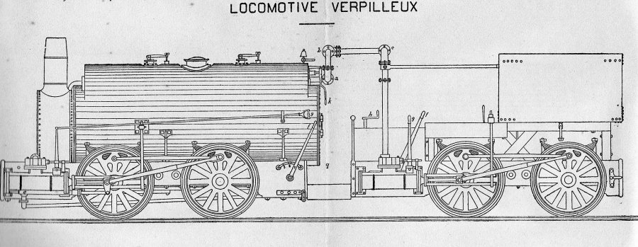 | Left: M. Verpilleux's steam tender: 1842
|
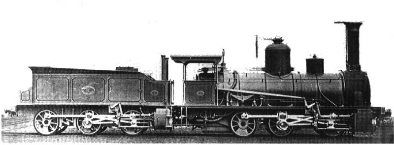 | Left: Sturrock's steam tender: 1864
|
The two cylinders on the tender were 12in by 17in, and were fed from the steam dome via a second regulator; there was no compounding. Steam reached the tender through a 23-foot long copper pipe which apparently had enough flexibility to bend with track curves. The exhaust steam from the tender was supposed to be condensed in 15 pipes at the bottom of the water tank, but this became ineffective when the water heated up, leading to clouds of steam coming from the rear chimney(s) and obscuring the crew's view of their train.
This version has two auxiliary chimneys at the front of the tender. Other versions had one or two auxiliary chimneys at the rear.
While some initial tests indicated that loads 50% greater could be hauled, Sturrock's steam tender was not a success.
It was unpopular with men asked to run it, because the fireman had to do almost twice as much shovelling, while the driver had to take care of two regulators and two separate sets of valvegear, for the same wages. There were other problems...
The unenviable situation of the crew was aptly described by Charles Fryer (in Experiments In Steam) thus: "In the course of the journey the footplate became insufferably hot; the back of the firebox was radiating more heat, the steam pipe supplying the tender's cylinders was adding its quota, while behind something like a giant steam-kettle was coming to the boil."
(From Experiments With Steam by Charles Fryer, pub 1990) According to the reminiscences of a retired fireman, the footplate crews hated them and attempted to sabotage them; this assertion often comes up but as far The Museum Staff know this has never been substantiated. Hot-running big ends were commonplace on the steam tenders, and as noted above the condensing was unreliable. It has also been said that the steaming of the boiler was inadequate for them to give full power.
All in all, this is about the worst way you could think of to introduce a new technology to the workforce. "Great news, chaps! Twice the work for the same pay!"
A Mr Bennett recalled:
"The heating surface provided was insufficient for the duplex engines when the load was such as to make a really severe call on the capacity of the machines. When no such demand was necessary, and especially when the engine was running light, the additional friction due to the extra motors and gearing was a positive disadvantage. This led drivers habitually to open both regulators, even when shunting. On such occasions it at least looked awkward to see two sets of six-coupled wheels and two exhausts engaged in giving a flying tip to a few, maybe only one or two trucks, and also engines running light with all cylinders working." |
Another flaw (according to Carter in Unusual Locomotives was that the extra power could not be usefully employed; starting was fine but the problem of stopping (in the absence of a brake system working on the whole train) meant that appropriately long trains could not be worked.
The steam tender was patented in Britain on 6 May 1863 and in the USA on 24 November 1863. A rather peculiar situation then arose because Sturrock then entered negotiations with the Board to see how much they would pay him for the use of his patent. This created an unhappy conflict of interest as the more steam tenders were built the more he would get paid, whether the tenders were successful or not. Anybody trying that sort of thing nowadays would be out on their ear in a second; normally you assign the patent to the company you work for.
Sturrock retired early, not in disgrace over the steam tenders, but because he had inherited a lot of money. Some of the steam tenders remained in use until 1868.
 | Left: Urban's steam tender: 1867
Tender cylinders: 350 x 400mm Total weight: 36 tonnes |
The locomotive was fitted with Walschaerts valvegear, (naturally) but the tender had only dual eccentrics, for forward and reverse at fixed cut-offs. This may well have been a bad idea. The wheels were of 1.2 m diameter. The boiler contained 368 fire tubes. The tender exhaust steam appears to have been sent straight up the chimney at the rear, without any attempt to make it heat the feedwater or assist with the smokebox blast.
This steam-tender appears to have been even more of failure than Sturrock's design. According to Phil Damply in Vapeur En Belgique, "...the tender-motors revealed themselves completely deficient and their mechanism the most inconvenient." Harsh words indeed.
Nevertheless, despite this faux pas, by 1872 Maurice Urban was a director of the National Railway Company of Belgium. In 1872 he set up a pioneering agency for boiler inspections.
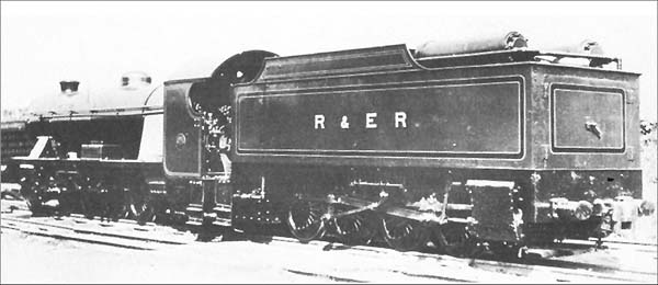 | Left: 0-8-0 steam tender of Ravenglass and Eskdale Railway
|
The line was originally built to transport hematite iron ore from three mines to a standard-gauge line at Ravenglass; the mines were quickly exhausted and the line later carried granite. Its history is complex; today it is a tourist attraction.
You can read more about the Poultney system here.
 | Left: 0-8-0 Poultney steam tender
|
TRIPLEX LOCOMOTIVES
The Triplex locomotives were attempts to use some of the (considerable) weight of the tenders to give some extra adhesion and tractive effort by making the tender another locomotive unit. There were already effectively two locomotive units because it was a Mallet design with an articulated front end.
![]()
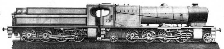
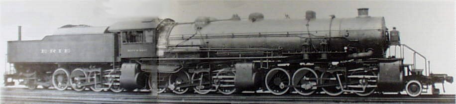 | Left: The Matt H Shay, a triplex used by the Erie RR: 1914
|
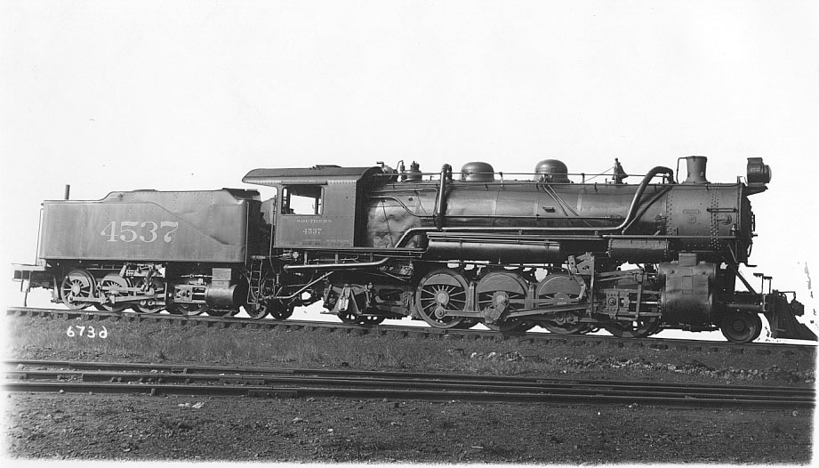 | Left: 'Duplex' Mikado 4537: 1915
|
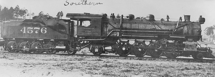 | Left: 'Duplex' Mikado 4576: 1915
|
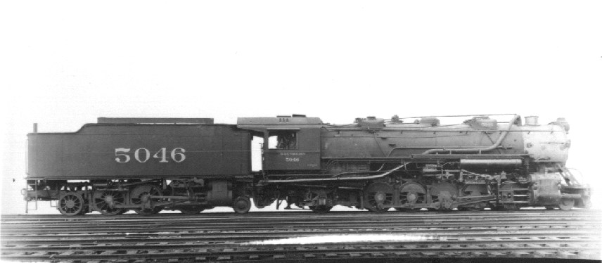 | Left: 'Duplex' Mikado 5046: 1915
|
![]()

|