The term "booster locomotive" covers a wide range of machinery all using the same basic principle- an extra set of small wheels and cylinders to provide extra tractive effort at low speeds, such as when starting, or on heavy gradients. This machinery was often mounted on the tender, or in some cases attached to the loco under the cab. In a few instances the additional small driving wheels were squeezed in between the main drivers and a leading bogie.
There were designs that had an extra drive system under the tender, intended for continuous use rather than just at starting- for example Sturrock's steam tenders, and the American Triplexes; these are not considered to be "booster" locomotives, though obviously they are closely related; the difference is a booster is working only for short periods, usually on starting, while a steam tender is always in use.
Booster engines have a good Wikipedia page.

THE TYPE AA-1 NO.1400 STEAM LOCOMOTIVE
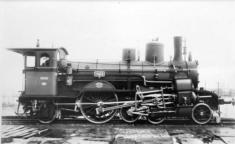 |
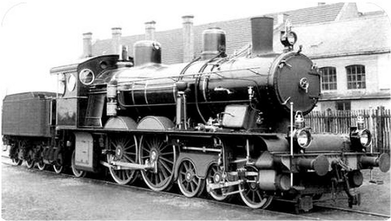
| Left: Type AA-1 Nr.1400 Steam Locomotive: 1896
This unique locomotive only had one pair of main driving wheels, but the design squeezed in a small booster pair of driving wheels between the conventional front bogie and the main drivers; they were normally held off 1.25 inches above the track by springs, but extra tractive effort was required the wheels were pressed down on the rails by a steam cylinder. This axle was powered by two small cylinders under the main cylinders, working completely independently.
It was built by Krauss in 1896, and was designed by their Chief Mechanical Engineer Richard von Helmholtz, for operation on the Royal Bavarian State Railways.
It appears that the auxilary axle is here in the lifted position.
No 1400 has a short Wikipedia page.
|
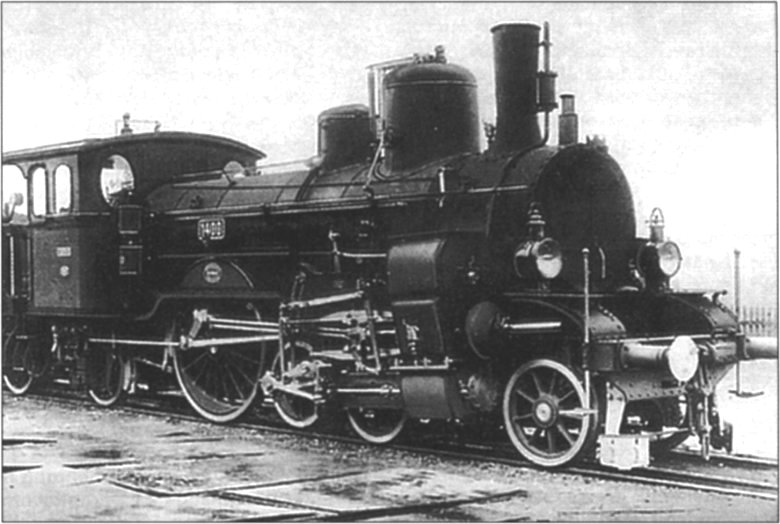 |
| Left: Type AA-1 Nr.1400 Steam Locomotive: 1896
This photograph appears to have been taken at the same time as that above. Note similarity of background and puddles. The auxilary axle is here in the lifted position.
You might think that such a complicated arrangement was asking for trouble, but it appears that 1400 ran successfully and economically for several years. In 1907 she was involved in an accident and was rebuilt as a conventional locomotive. Also the design was never repeated, so one must assume that ultimately it was not a good idea. The rebuilt engine was the last Bavarian 4-4-0 locomotive to be retired, in 1933.
The Whyte system classifies it as a 4-2-2-2 tender locomotive.
|
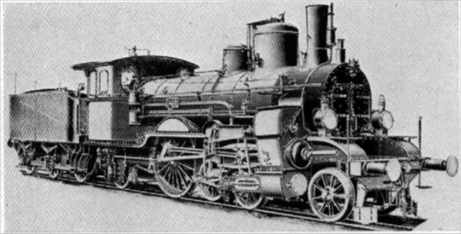 |
| Left: Type AA-1 Nr.1400 Steam Locomotive: 1896
This is a different reproduction of the image above, retouched to remove the local scenery.
|
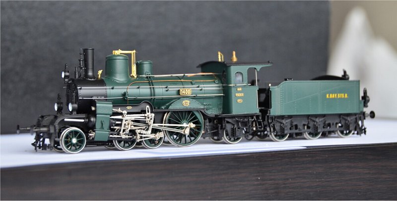 |
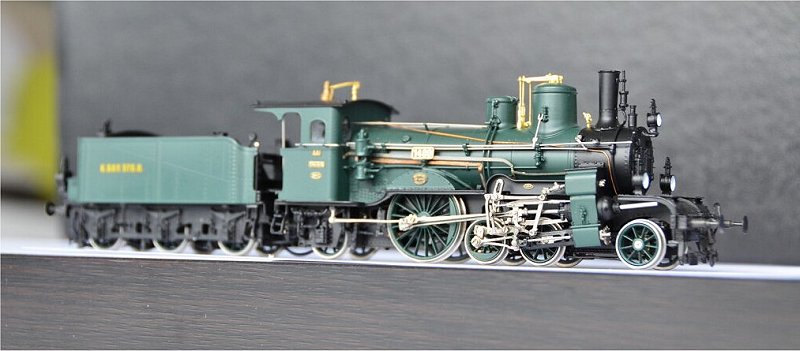
| Left: Micro-Metakit 91001H model of Nr.1400 Steam Locomotive
It seems that Micro-Metakit make models of almost everything. They are precision museum-quality models, cost some �3000 each.
It is not known if the model incorporates a lifting mechanism for the booster axle.
|
 |
| Left: Micro-Metakit 91001H model of Nr.1400 Steam Locomotive
The other side of the model.
|
THE VON CLEMM P3-11 LOCOMOTIVE
 |
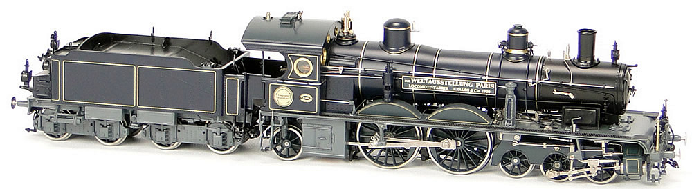
| Left: P3.II, "Dr. von Clemm "Royal Bavarian State Railroad
This locomotive was built on the "System von Clemm" in 1900 by Krauss. It was designed for express service in Bavaria. It had a most unusual wheel arrangement of 6-4-2. Two modestly-sized cylinders at the front drove the central axle of the six-wheel front bogie; a close examination of the photograph shows that the central bogie wheel is lifted off the rail, presumably by a mechanism like that of No 1400 above. It is believed that the front driving wheels were only used for starting.
The rectangular box just ahead of the cab looks as though it might house the cylinders driving the four central wheels, but in fact housed fore-and-aft balance weights driven by a rod from the central wheels.
|
The locomotive was painted in dark blue, gray, and black with gold lining and was provided with an eight wheel tender for the 1900 Paris World Exhibition, where it won a gold medal. At this point it had a Westinghouse air pump.
 |
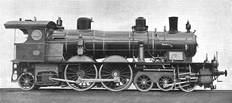
| Left: P3.II, "Dr. von Clemm "Royal Bavarian State Railroad
By 1902 the locomotive had been given a 3-axle tender 3T16, and repainted in purple-violet, black,and red with red lining. At this point it had a Schleifer air pump.
|
The board on the side of the boiler says "Paris World Exhibition" in German.
 |
| Left: P3.II, "Dr. von Clemm "Royal Bavarian State Railroad
This picture shows a cutaway that reveals the fore-and-aft balance weights under the front of the cab, which slide on guides sloping with respect to the horizontal. This was presumably to optimise the vertical balancing.
Source: Scientific American 26 Jan 1901, p55
|
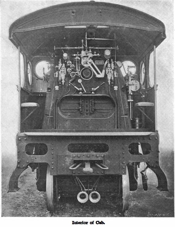 |
| Left: The cab of the P3.II
Note the linkage to the regulator so the driver can stand on the right, rather than in front of the firebox.
Source: Scientific American 26 Jan 1901, p55
|
AMERICAN BOOSTERS
Boosters were popular and highly successful in the USA, and were also used to a lesser extent in Canada and Great Britain.
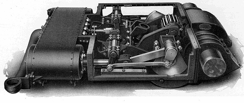 |
| Left: Franklin booster bogie
Franklin was one of the major American companies making booster systems. They produced 4-wheel booster bogies to fit under tenders, and 2-wheel units to fit under the cab of the locomotive.
The two steam cylinders are at left with the valve-chest between them. At right is the driven axle.
|
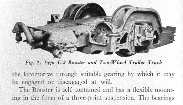 |
| Left: Two-wheel Franklin booster bogie
Source: The Locomotive Booster Instruction book No 102-A. Published by the Franklin Railway Supply Company Inc, 1942
|
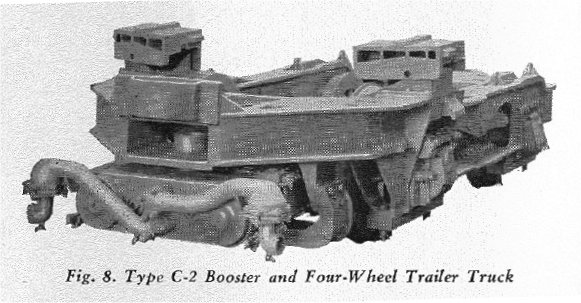 |
| Left: Four-wheel Franklin booster bogie
Source: The Locomotive Booster Instruction book No 102-A. Published by the Franklin Railway Supply Company Inc, 1942
|
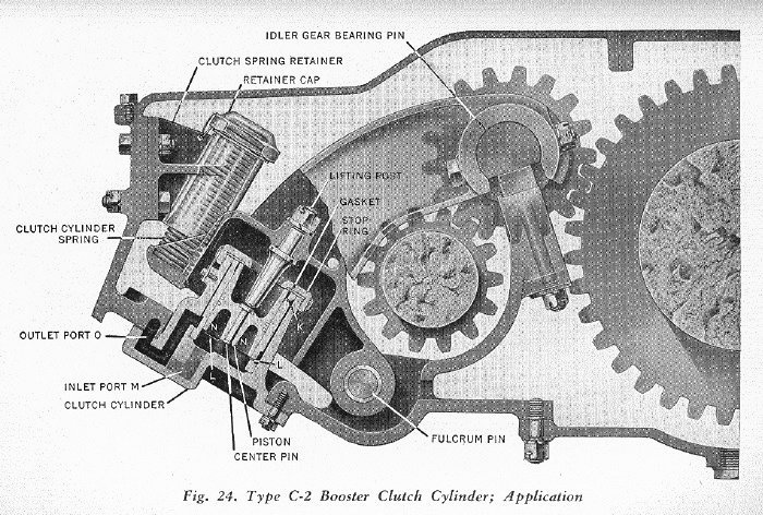 |
| Left: Franklin booster clutch system: in gear
The idler wheel was thrown in and out of engagement with the other gears by a relatively small movement of the cylinder
Source: The Locomotive Booster Instruction book No 102-A. Published by the Franklin Railway Supply Company Inc, 1942
|
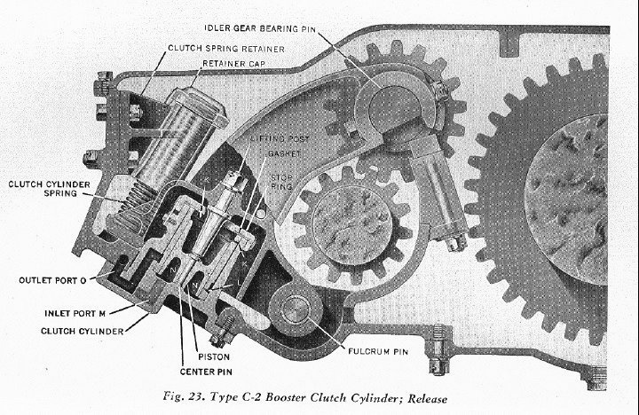 |
| Left: Franklin booster clutch system: out of gear
The idler wheel is now out of engagement with the driven gear at right.
|
GRESLEY'S BOOSTERS
Nigel Gresley was one of the great British locomotive engineers. In 1924 he ordered a two-wheel booster from the Franklin Supply Company, and fitted it to 4-4-2 Atlantic locomotive No 4419 in place of the original trailing 2-wheel truck, in order to increase the adhesion weight. The London and North Eastern Railmay (LNER) had a number of Atlantics which had large boilers with sufficent steaming capacity that it was impractical to convert to 4-6-0 format. Tests with this and other locomotives were basically successful, but the idea was abandoned by the mid-1930's as other more powerful engines became available.
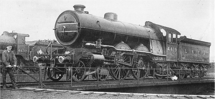 |
| Left: Franklin booster fitted to LNER No 4419: 1924
The locomotive is shown on a turntable. Note the wide firebox that made conversion to 4-6-0 format impractical.
|
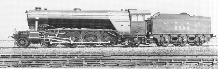 |
| Left: Franklin two-wheel booster fitted to LNER No 2393: 1924
The steam supply pipe for the booster can be seen running below the cab.
|
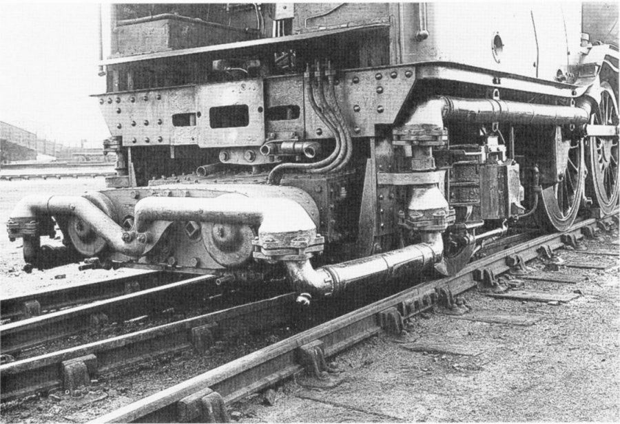 |
| Left: Franklin two-wheel booster fitted to LNER No 2393: 1924
Showing the steam supply pipe with swivelling joints and a telescopic pipe section.
|
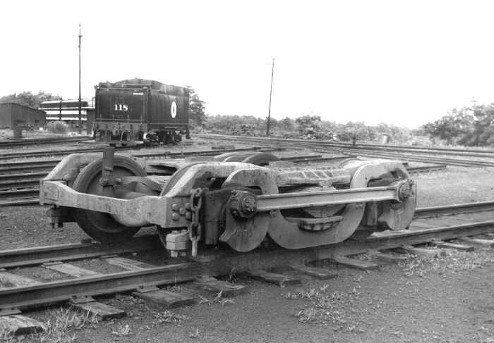 |
| Left: Four-wheel Franklin booster used by LNER: 192?
Note very substantial coupling rod and correspondingly heavy balance weights.
|


