There were several reasons for strange chimney designs. Here are some:
IN PURSUIT OF MORE DRAUGHT
 |
|
MORE DRAUGHT
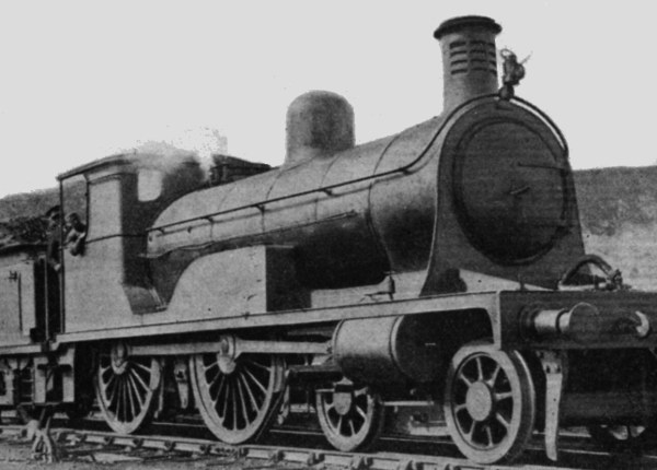
Left: Loch class 4-4-0 with louvred chimney
I originally thought that this louvred chimney design design, characteristic of Highland Railway practice in the 1890's, was intended to lift the smoke clear of the boiler. The truth is still unclear, but it now appears more likely that it was intended to maintain some sort of draught when the engine was running with steam shut off, as occurred frequently on the up-and-down Highland line.
The louvred chimney was introduced by David Jones, (1834-1906) locomotive superintendent of the Highland Railway from 1870 to 1896. It had a central exhaust tube and an outer visible tube with louvres intended to intercept the air, and create a draught on the inner tube. No comments have been found on how well it worked; my own thought is that those small louvres would not have conveyed much air.
|
The Loch class 4-4-0s of 1896-1917 had a very high power/weight ratio. They were among several classes carrying the louvered chimney. When No 14393 Loch Laoghal was photographed it was owned by the LMS Northern Division. For more on Jones and his locomotives, see Wikipedia

CONSUMING SMOKE & EMBERS
 |
|
CONSUMING SMOKE & EMBERS
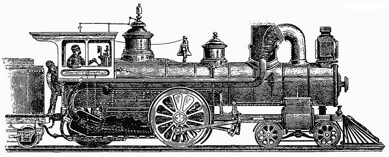
Left: The Coventry engine: 1884
Excerpt from Scientific American September 13, 1884 Page 163:
A Smoke Consuming Locomotive
"An engine of a novel type, designed by Charles B Coventry, has recently been constructed by the Brooks Locomotive Works, for the Chicago Locomotive Improvement Company. The headlight is placed where the stack generally is, while the stack is at the rear of the boiler and close to the cab. The boiler is one of the largest manufactured (what is known as a 60 inch shell), and the smoke, gas, etc., traverse it twice, along the bottom and back on top to the stack. This makes such a good combustion that the finer particles of fuel, the gas, and the smoke are almost entirely consumed and when the engine is going at full speed, it is impossible to see any smoke. The smoke stack itself is very small, being not more than seven or eight inches in diameter. Among the advantages of this invention it is said it gets a steady, even draught, reduces the waste of fuel to a minimum and throws no cinders, sparks or fire. The locomotive is peculiar in appearance, but it is said that it does its work well. It weighs forty tons."
The excerpt suggests that a locomotive was actually built. However, no trace of it has been found on Google.
Diagram source: US patent No 287,505. "LOCOMOTIVE BOILER" Oct 1883
|
 |
|
CONSUMING SMOKE & EMBERS
Left: Hadlock's engine: 1892
"The figure depicts a device to prevent sparks and embers from falling on the train itself and on the surrounding lands and buildings, while also promoting more complete combustion of the fuel. This device has been patented by Mr. Edson G. Hadlock of Big Spring, Texas."
Source: Smoke Eating Locomotive The Philosopher's Stone 1892
Thanks to Karl Schmidt for alerting me to this design.
|
From The Philosopher's Stone:
"The chimney is bent backwards and a spark arrestor of the same height as the former is fitted to a tin below. The spark arrestor is divided into two chambers by a curved partition, the opening of the front one being in a horizontal plane with the mouthpiece of the chimney, while the rear chamber opens to the air; both chambers communicate with the box underneath. This can has a double deflector erected in the middle part of it, and from each side of the can tubes run along both sides of the steam boiler to a discharge point which opens into the charcoal box below the screen."
"Each of these tubes also has a branch communicating with the firebox, but which side openings are not to be used simultaneously with the openings at the ends of the two main tubes. In the bottom of the box for the burned-out coals is a damper or draught-flap, from which a tube runs up into the screen. In the bottom of the ash pan there are crossbars and similarly mounted in a slider which is arranged to be manipulated by means of a lever going up into the screen. With this device, the burned-out coals and ash can be dammed (damped?) at any point. Finally, at the rear of the ash pan is a damper that can be manipulated from the screen."
SMOKE DISPERSAL
 |
|
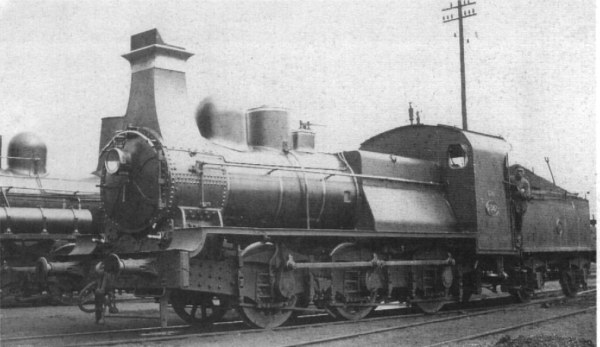
Left: Square chimneys like this were unique to Belgian locomotives.
The flat chimney front (which would not have caused that much air resistance at the modest speeds of these locos) was designed to clear smoke from the boiler to improve visibility. The front lip at the top of the chimney, known as a visi�re or "visor" was supposed to improve the draught.
This is a type 25 locomotive built in 1895 by the maker Franco-Belge. Photo date unknown.
Square chimneys were fitted in the period 1884 - 98.
|
 |
|
SMOKE DISPERSAL
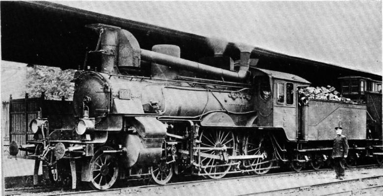
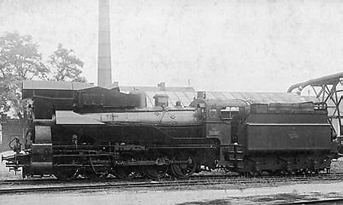
Left: Prussian S3 No 237 with two "stove pipes" either side of the steam dome.
This modification followed complaints from the crew about smoke obscuration.
This photo appears to have been retouched in a less than subtle manner, hence the black background. Even in well-regulated Prussia, it would be hard to get the coal in the tender quite that flat...
|
Above: Prussian S3 No 237 again, showing more clearly that there were two "stove pipes", running each side of the steam dome.
Presumably this arrangement did not help the draught, for there appears to be some sort of valvebox over the normal chimney position that would allow the exhaust to be sent straight out in the usual way when maximum steam generation was needed. A horizontal control rod appears to lead back to the cab.
Since locomotive aesthetics seem to matter, the stove-pipe solution did not find favour. R P Wagner's deflector plates were preferred.
 |
|
SMOKE DISPERSAL
Left: A Hungarian MAV328 501 with special chimney: 1920
The idea being, no doubt, that air would enter the openings at the front of the cowl and be deflected to blow the chimney smoke upwards. The 2C h2 locomotive was built by Henschel of Germany; the MAV number indicates that the locomotive operated in Hungary.
No further facts known, but it looks as though the amount of air that would be so deflected would be completely inadequate for the job.
From Dampflokomotiven und ihre Bauteile by Franz P Flury
ie Steam locomotives and their Components
|
 |
|
SMOKE DISPERSAL
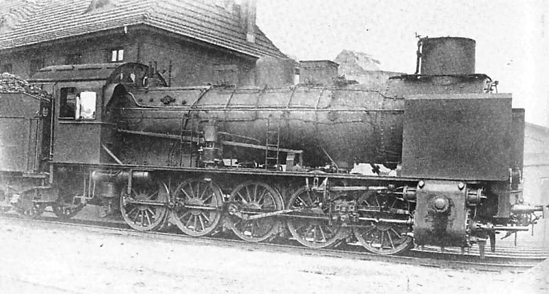
Left: A German DR57 with special chimney: 1910
For quite I while I suspected that the pipes running into the chimney were for steam jets intended to raise the smoke clear of the boiler; presumably only intended for occasional use, such as when dealing with adverse wind directions, or a lot of steam would have been wasted.
However, Hans-Dieter Jahr tells me (8 Jan 09) that the pipes are actually for a feedwater-preheater built into the unusually wide chimney, and only the cowling is concerned with smoke management.
From Dampflokomotiven und ihre Bauteile by Franz P Flury
ie Steam locomotives and their Components
|
 |
|
SMOKE DISPERSAL
Left: A German DR01 with a ramp deflector behind the chimney: 1926
Locomotive built by AEG.
From Dampflokomotiven und ihre Bauteile by Franz P Flury
ie Steam locomotives and their Components
|
 |
|
SMOKE DISPERSAL
Left: A German DR43 with air-deflecting ramp in front of the chimney: 1928
Locomotive built by Schwarzkopf.
From Dampflokomotiven und ihre Bauteile by Franz P Flury
ie Steam locomotives and their Components
|
 |
|
SMOKE DISPERSAL
Left: A Norwegian C27 with vertical deflectors each side of the chimney: 1912
This reminds me irresistibly of an alarmed Dogbert.

Locomotive built by Thunes. (?)
From Dampflokomotiven und ihre Bauteile by Franz P Flury
ie Steam locomotives and their Components
|
 |
| SMOKE DISPERSAL
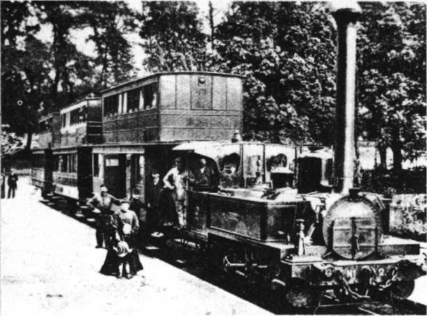
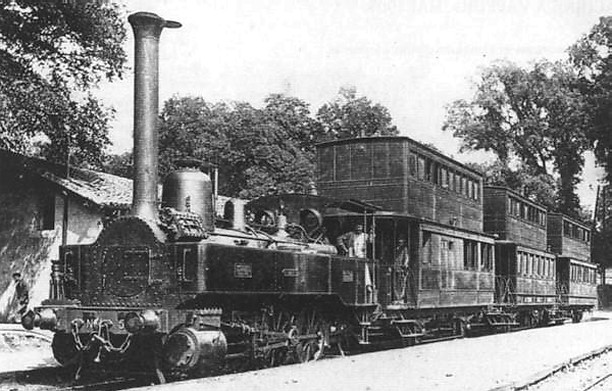
Left: This engine, with its exceedingly lofty chimney, is the Anglet, built by Anatole Mallet in 1876.
The Bayonne-Anglet-Biarritz line in France used double-decker coaches, and so a very tall chimney was required to lift the smoke clear of the upper deck. The Anglet was the first French compound locomotive.
This photo was taken at Bayonne, home of the Bayonet.
|
 |
|
Left: Another view of Anatole Mallet's compound.
Note the swivelling damper plate at the top of the chimney.
|
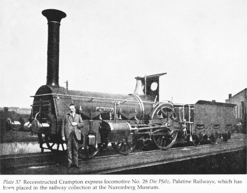 |
| Left: A towering chimney on "Die Pfalz": built 1853
The chimney rises about 8 feet above the top of the boiler. A fine reconstruction of this locomotive, built in the late 1920's, can be seen in the Nuremburg Railway Museum. It is a Crampton type, with single pair of driving wheels right at the back, the axle running behind the firebox. This gave a low centre of gravity.
"Die Pfalz" means "The Palatinate", which is the region of south-west Germany for which it was constructed. There were four engines in the batch, numbered 26 to 29. They ran until about 1880, and were then scrapped. They required a good deal of maintenance due to excessive flexibilty in the sandwich frame construction.
|
 |
|
Left: Southern Pacific Railroad deflector chimney
This strange device was intended to reduce smoke obscuration in tunnels. The idea was that the smoke, instead of hitting the tunnel roof and bouncing back down around the locomotive, would be sent sideways and down the tunnel sides.
No more was heard about it so presumably it was not too successful. A similiar device, designed for spark and cinder deflection was rather than smoke deflection, was fitted to the Boynton Bicycle locomotives; see below under SPARK SUPPRESSION.
From American Engineer and Railroad Journal September 1909, Page 368
|
 |
|
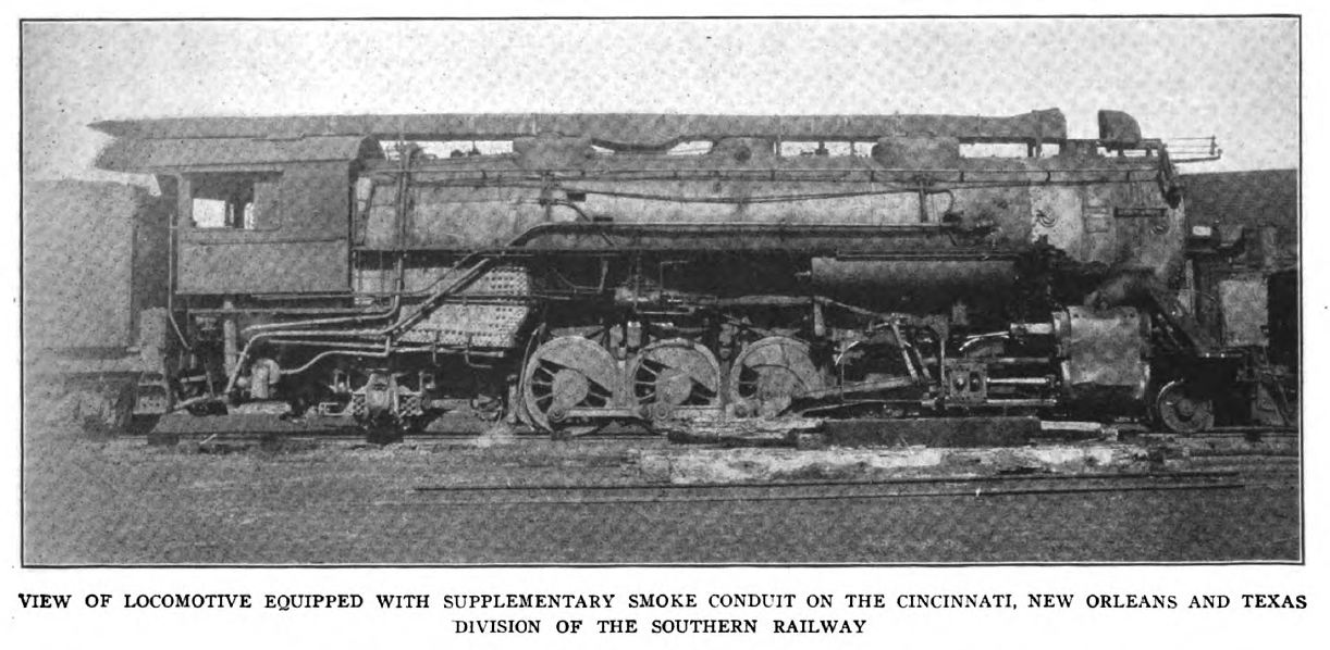
Above: Southern Railway smoke duct: 1920
The Cincinnati, New Orleans and Texas Pacific division of the Southern Railway had a number of poorly-ventilated tunnels on its route from Cincinnati to Chattanooga. (no doubt something to do with the Chattanooga choo-choo) To reduce the sufferings of the engine crews working the heavy Santa Fe engines, a smoke duct made from 3/16" steel was placed on top of the engine, with its exhaust at the back end of the cab roof. A deflecting bonnet above the normal chimney was moved by a pneumatic cylinder to deflect the exhaust through the duct when working in tunnel; in the open the chimney exhausted straight upwards as usual. The wear on this bonnet was severe, due to cinders being blasted upward through the chimney.
For a long time I only had a very poor quality picture here; this is much better, despite the moire. Many thanks to Tom Bates for this version.
From Railway & Locomotive Engineering Nov 1920, Page 315. Vol XXXIII, No 11
|
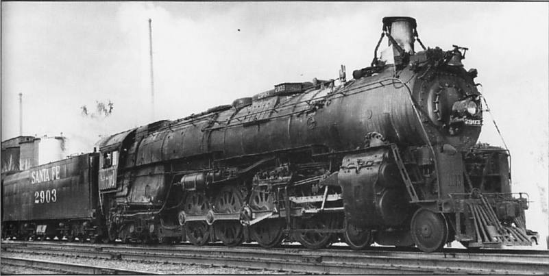 |
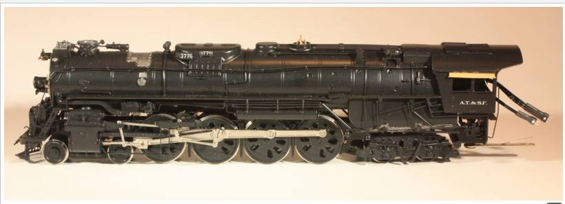
| Left: AT & SF 4-8-4 locomotive with extending chimney
|
The 2900-series 4-8-4 (Northern configuration) locomotives built for the Santa Fe railroad were the heaviest of that wheel format ever built, weighing 227 tons each. This is No 2903 in California in 1950, with its telescopic chimney extended. This lifted the smoke above the locomotive, and may have improved the draught. The chimney was raised and lowered by a pneumatic cylinder that can be seen just behind it, (presumably powered from the braking compressed-air system) under the control of the engineer.
 |
| Left: Model of AT & SF locomotive with extending chimney
|
Here the chimney is retracted; the operating cylinder can be seen to the right of it.
The chimney would be retracted mainly for bridges. The Santa Fe railroad did not own a lot of tunnels, except in California. There was one tunnel in New Mexico, and three in Arizona. They put up standard signs that said "Lower Stack Extension" at the relevant locations, but engineers did not always respond in time to save the chimney.
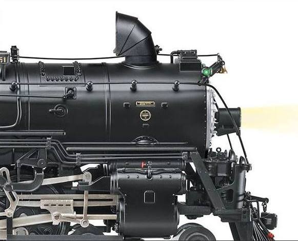 |
| Left: A "smoke bonnet" on a AT&SF 4-8-4 locomotive
Some of the engines assigned to California service, especially the Valley Division, had hinged "smoke bonnets" that were swung into action in tunnels, apparently to prevent the exhaust from damaging the tunnel roof. The smoke would therefore have been directed back towards the cab instead, so these thing must have been something of a mixed blessing.
No 3751 carried one of these when it was retired, and No 3759, displayed in Kingman, Arizona, still has one.
|
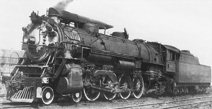 |
| Left: A Southern Railway 4-8-4 locomotive with a Wimble smoke duct
This is No 6495 fitted with a Wimble smoke duct, designed by a CNO&TP engineer of that name. The CNO&TP Cincinnati Southern Region had 27 very tight and ill-ventilated tunnels, and therefore was called "The Rat Hole" division. The Wimble smoke duct slid forward and covered the chimney when inside the tunnels, directing the exhaust back over the sand dome and then upwards. Passenger engines traveled faster and with lighter loads than freight engines, and were fitted with a shorter version of the Wimble duct. The sliding section was pneumatically operated under the control of the engineer.
|
Note the smoke leaking between the chimney and the duct.
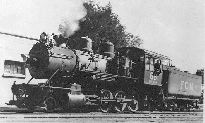 |
| Left: A Mexican 2-8-0 locomotive with a split chimney
This is locomotive FCM 68 of the Ferrocarriles Nacionales de Mexico. It was built by the Baldwin Locomotive Works. (date unknown)
The neat Y-shaped split chimney was to direct the exhaust away from central catenary wires.
|
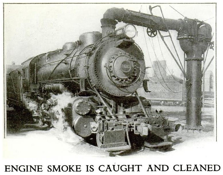 |
| Left: Chicago locomotive with smoke-catching pipe: 1931
This may not be a chimney as such, but it is certainly an arresting image. While the locomotives were raising steam the thick smoke produced was captured by this arrangement to reduce the pollution of chicago. The smoke was scrubbed (presumably with water spray) before being released to the atmosphere.
It appears the arm on the right-hand side of the column has been renoved.
From Popular Science, May 1931, p60
|
 |
| Left: Patent drawing of smokejack: 1923
It appears the arrangement above was called a 'smokejack', though that is more commonly a name for a fan in a chimney (a sort of crude gas-turbine) geared down to turn a roasting-spit.
US patent 1,478,263 was issued to Barton S Snow in 1923, and assigned to the T W Snow Construction Company of Chicago, Illinois. It is almost certainly the precursor of the design in the photograph. The patent refers to reducing smoke inside roundhouses rather than reducing local pollution generally, and makes no reference to scrubbing the exhaust gases but merely "discharging them to any desirable point" presumably a chimney. The possibility of using an exhaust fan to move the gases is mentioned.
The pipes are telescopic both vertically and sideways. Their vertical movement is by turning handwheel 33 which is attached to a screw-thread inside the pipe, which is counterbalanced by weights 17. Lateral movement is by a similiar internal thread operated by the chain 18. The smoke goes down an underground conduit 5 and away.
What seems to be missing is any way to close off the pipes when they are not in use, which suggests the possibilty of smoke going into one arm and straight out of the other.
Thanks to Douglas W Jones for drawing this patent to my attention.
|
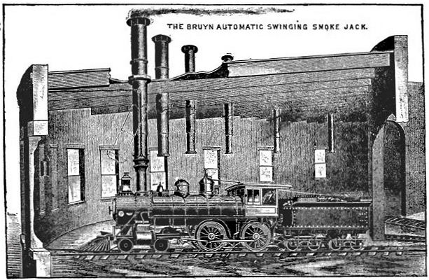 |
| Left: The Bruyn smokejack: 1907
Once again, this may not actually count as a locomotive chimney as such, but it certainly has an interesting look to it. These telescopic smokejacks are counterbalanced by weights hung against the wall (see extreme left) and had a ball-and-socket joint to allow alignment with the locomotive chimney.
From Locomotive Appliances by Marshall A Kirkman p433, 1907 World Railway Publishing Co
|
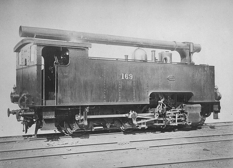 |
| Left: Rack locomotive for Japan with T-chimney: 1923
The Usui Pass railway in Japan opened in 1892. It had gradients of up to 1:15, and 18 bridges and 26 tunnels in its 11.2 km length. It was worked with rack locomotives on the Abt system.
The first locomotives were of German origin, but in 1895 two engines were delivered from Beyer Peacock of Manchester in 1895. Here is one of them; rack locomotive AH 169, later called No 3920, in delivery condition with its T-shaped chimney. These were fitted as the earlier engines had had problems with smoke dispersal. The T-chimneys allowed smoke to be exhausted at either the front or rear of the engine, controlled by a valve operated from the cab. Note the side tanks extended to the front of the engine to increase coal and water capacity.
The scheme does not appear to have been successful as it was later removed and a conventional chimney fitted, with steam being condensed in the water tanks as on the London Underground. Oil firing was introduced in 1909. No 3920 was scrapped in 1917, while No 3921 was destroyed in the Great Kanto earthquake. This is a not uncommon hazard of Japanese railway operation.
The Usui Pass railway has a Wikipedia page. It is in German but the Translate button works fine.
|
IN PURSUIT OF THERMAL EFFICIENCY
 |
|
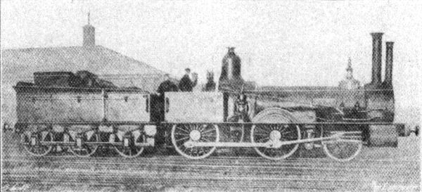
Left: The "double-chimney" locomotives of Joseph Beattie. LSWR, 1855
This design was a fast goods engine for the London & South Western Railway, designed and built by Joseph Beattie at Nine Elms in London. They were the first engines to use coal- rather than coke- on the LSWR.
What appears to be a small secondary chimney in front was actually a vertical jet condenser that formed part of Beattie's first type of feedwater heating apparatus.
|
Beattie produced a number of engines with feedheaters, and it is not known which of them is portrayed above. No 135 "Canute" had a single feedheater column, while No 167 "Atalanta" had two, disposed symmetrically in front of the actual chimney. These engines were reputed to have the highest thermal efficiency of any in the country, though the accuracy of the tests on which this claim was based is dubious.
Joseph Hamilton Beattie, (1808-71) was Locomotive Superintendant of the LSWR from 1850 to 1871. He took out his first patent for feedwater heating in 1854.
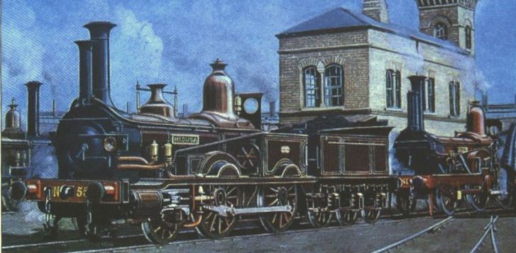
Above: Detail from a painting by Cuthbert Hamilton Ellis of Beattie's locomotives at Nine Elms depot.
The "Medusa" at the front has one extra "chimney" that is really a feedheater, but the unnamed locomotive behind it has two columns in front of the real chimney. Note extra pipework at the sides of the smokeboxes. At the moment it is not clear whether the one-column or the two-column version came first.
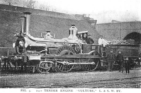 |
| Left: The "Vulture" 2-4-0 engine of the L&SWR.
This engine design was introduced in 1856; note that it looks very similar to the "Medusa" shown just above. The single vertical column in front of the real chimney was the jet condenser; part of the exhaust steam entered this and was condensed by a jet of water, the result being hot feedwater. Some of this flowed back to the water in the tender, warming it up, and the rest going to the feedpump, which pushed the hot water through a tubular heat exchanger in the smokebox to heat it further and thence to the boiler.
From an article "Locomotive Feed-water Heating and Boiler Feeding" by George Willans in the the journal The Locomotive 15th Feb 1921, p44. Presumably he wsa a relative of Peter William Willans, designer of the famous high-speed steam engine.
|
Trials were conducted which appeared to show that the feedheating apparatus gave a 20% saving in fuel consumption, and sometimes as high as 33%. Whether anyone believed these figures at the time is unknown, but certainly George Willans wasn't buying it.
The column technology was ultimately replaced in 1858 by more conventional heat exchangers at the side of the boiler; this remained the standard feedwater heater on the L&SWR, but was gradually discarded after W. Adams took over in 1878. Clearly Mr Adams wasn't buying "33%" either.
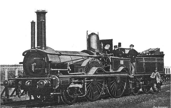 |
| Left: The "Atalanta" 2-4-0 locomotive of the L&SWR.
This gives a better view of the two-column version.
Note that the middle gentleman on the footplate is wearing a stove-pipe hat. Most appropriate.
|
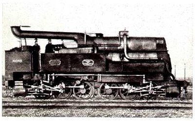 |
| Left: M Petiet of the Nord strikes again. 186?
A duplex-drive locomotive on the French Nord network. The hot gases passed through the boiler tubes as usual and then turned back to pass through the steam-dryer on top of the boiler. This was before the introduction of the Schmidt superheater in 1898. It is thought that the amount of extra heating of the steam was in fact quite small.
For some reason I always think of elephants when examining Petiet's designs.
For more strange chimneys prompted by a desire for thermal efficiency, see also: Petiet's Experiment and Franco-Crosti Boilers.
|
|
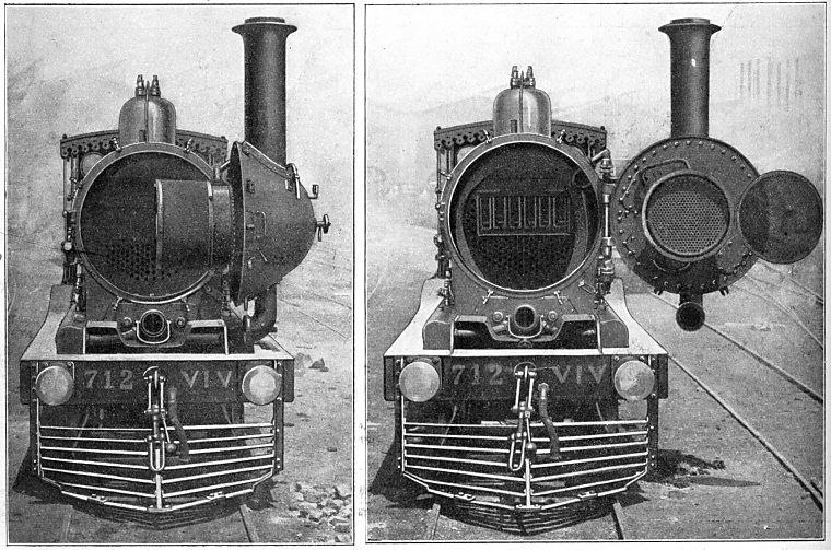
Above: Locomotive with preheater for the Egyptian State Railway, by F H Trevithick: 1902
This bizarre construction, which could have been inspired by Petiet's designs, was a modification of an existing 0-6-0 to test the possibilities of feedwater heating rather than steam drying. The cylindrical heater a was 4.25 m long with a diameter of 685mm, and was connected to the smokebox by a 450mm wide pipe. The feedwater was heated by both the combustion gases, which passed through 91 smoke-tubes a1 of 47mm diameter, and the exhaust steam, which was passed through in a pipe c of 230mm diameter to a horizontal blastpipe d. As a result of this construction the combustion gas heating area was 58 m2, but the exhaust steam heating area was only 3.3 m2. The feedwater temperature was raised to 133 �C.
Judging by the height of this assembly, the loading gauge in Egypt must have been a good deal higher than in England; perhaps there simply weren't any overbridges. It is probable that this bizarre form of construction was used simply because it was the cheapest way to try out feedwater heating. Note the fancy pelmet around the cab roof; very tasteful. This sort of decoration seems to have been common on Egyptian locomotives. The locomotive weighed 33 tons without the tender.
The project was designed by F H Trevithick, a grandson of the great Richard Trevithick. He was chief mechanical engineer of the Egyptian State Railways from 1883 to 1912. The source gives his name as F R Trevithick, which caused some problems in tracking him down.
From Zeitschrift Des Vereines Deutscher Ingenieure (The magazine of the Association of German Engineers) for 10 May 1913
|
|
Above: Patent drawing of locomotive with preheater for the Egyptian State Railway, by F H Trevithick: 1902
The indefatigable staff of the Museum have answered a few of the questions about this remarkable design by finding the drawing for a German patent. (K13, No 134562) The patent appears to have been taken out in 1902, a long time before the 1913 article which showed the photograph above.
The blast-pipe d is at the rear of the heater, above the front of the cab. A U-shaped pipe can be seen running down from the heater, to the left of the smoke-box b, and terminating in what was presumably a non-return valve feeding the boiler. The cylindrical volume h wrapped around the heater acts as a substitute for the removed steam-dome. Note that in the photograph above the steam-dome was retained; there are several differences been the patent drawing and the photograph, as the patent represented a purpose-designed locomotive rather than an improvisation.
There was a problem; the exhaust steam tended to condense in the feedheater, and although drain pipes were fitted, some of the water was blown out of the chimney. In later trials the feedwater was heated by the combustion gases only, and a feedwater temperature of 115 �C was achieved.
From Zeitschrift Des Vereines Deutscher Ingenieure for 20 Dec 1902
|
 |
| Left: The Pepperpot Special; another preheater locomotive for the Egyptian State Railway, by F H Trevithick: 19??
F H Trevithick's next experiment had six feedwater heaters arranged in a saddle formation over the smokebox. Each heater was 0.91m long, and composed of 31 tubes of 47mm diameter. The total heating surface of tubes and cylinder shells was 31.5 m2. The cross-sectional area for passage of the exhaust gases was 2400 cm2. The feedwater flowed sequentially through the six cylinders and reached an average temperature of 110�C.
Many thanks to Felix Brun for helping with translation from the German.
From Zeitschrift Des Vereines Deutscher Ingenieure for 10 May 1913
|
|
Above: The Pepperpot Special again, with its remarkable angled chimney. Heaters partly sectioned.
There seems to be another little tubular heater perched just above the first driving wheel. What looks a steam feedpump can be seen at the front of the cab, (injectors don't work with hot water) just below the safety valves, and I suspect this extra little heater was intended to make use of the exhaust from the feedpump for a bit more feed heating. If that is the case, it seems very doubtful if it was worthwhile.
From Zeitschrift Des Vereines Deutscher Ingenieure for 10 May 1913
|
|
Above: F H Trevithick's swinging chimney. Another of his preheater designs for the Egyptian State Railway
In this design the aim was to secure better flow of the exhaust gases by mounting the preheater and blast pipe on the smokebox door. The blast pipe was under the base of the chimney in the usual way. The big pipe just under the smoke box carried the cylinder exhaust to the blast pipe, through some sort of coupling. The feedwater being preheated entered and left the swivelling section through conical joints in the centres of its two hinges, sealed by stuffing boxes. You can just see the pipes in the right photograph. There was also a connection for the steam blower but it is not clear where it was.
Trevithick claimed the boiler steamed easily with good superheating and preheating, without needing a high gas flow rate. During starting the steam blower easily maintained the gas flow. He said all the pipe connectors worked well. The smokebox was originally fitted with a spark screen that was later removed; presumably that it is it shown hinged to the preheater in the rightmost picture.
Many thanks to Felix Brun for helping with translation from the German.
From Zeitschrift Des Vereines Deutscher Ingenieure for 17 May 1913
|
This fascinating excursion into locomotive design in Egypt has underlined the fact that there seems to be very little documentation on the Egyptian railways. Motor Books had nothing...
|
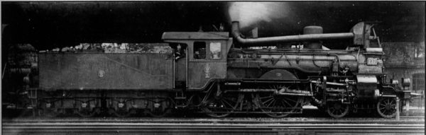
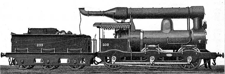
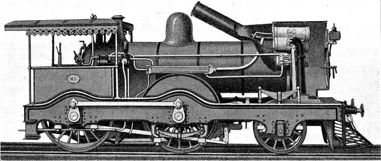
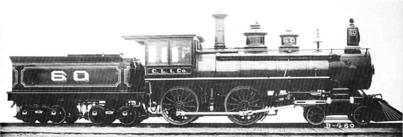
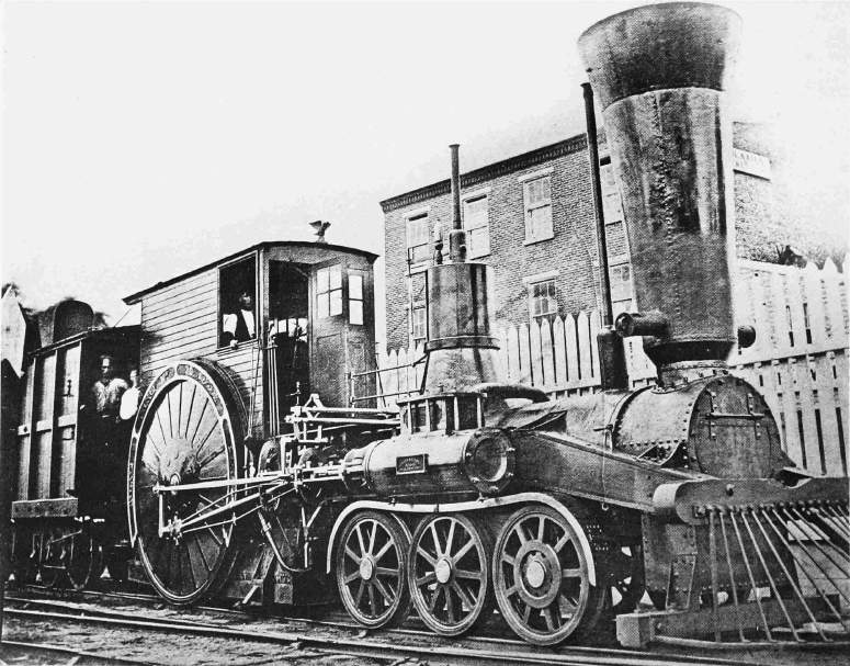
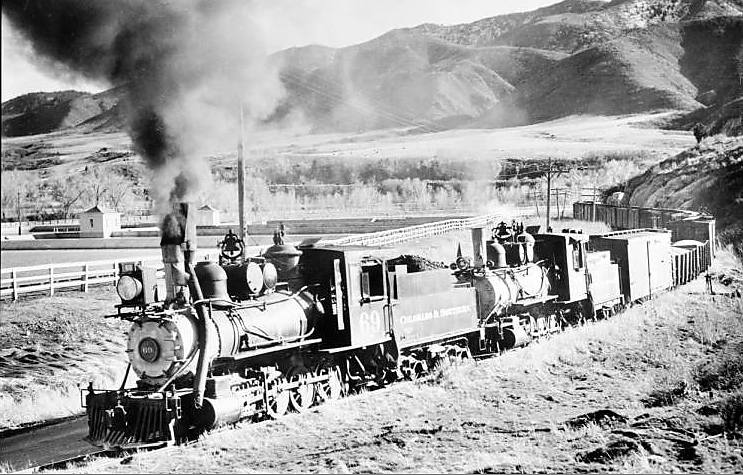
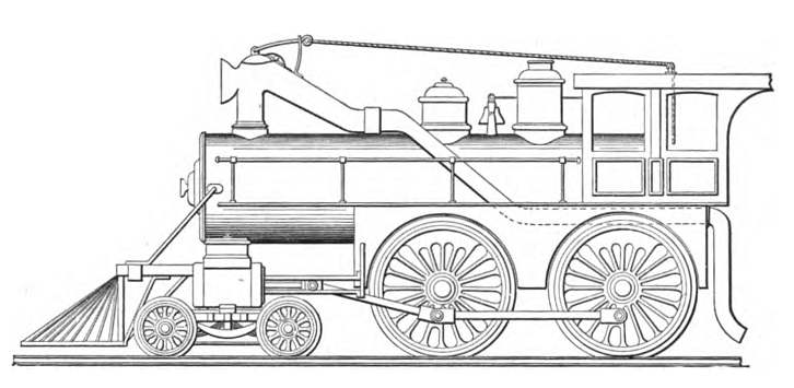
Above: Rear-mounted chimney on Chicago No 60, built for the Chicago Locomotive Improvement Company: 1884
This at-first-sight conventional 4-4-0 locomotive was built for the Chicago Locomotive Improvement Company by the Brooks Locomotive Works. A second look reveals that it has its chimney mounted not at the front, but just ahead of the cab. The pipe running from the front to just below the chimney presumably carried the exhaust steam from the cylinders to the blastpipe. Information on this machine is scarce, but it appears that the boiler had return flues that brought the gases to the rear of the boiler, to increase the heating area. A useful side-effect would be that smoke and steam were kept out of the driver's line of sight.
Picture from A Locomotive Engineer's Album, by George B Abdill, 1965
|
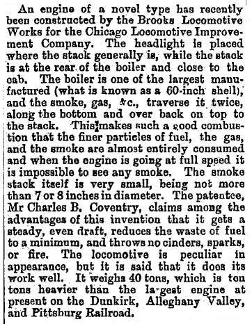
Excerpt from Scientific American September 13, 1884 Page 163:
A Smoke Consuming Locomotive
"An engine of a novel type, designed by Charles B Coventry, has recently been constructed by the Brooks Locomotive Works, for the Chicago Locomotive Improvement Company. The headlight is placed where the stack generally is, while the stack is at the rear of the boiler and close to the cab. The boiler is one of the largest manufactured (what is known as a 60 inch shell), and the smoke, gas, etc., traverse it twice, along the bottom and back on top to the stack. This makes such a good combustion that the finer particles of fuel, the gas, and the smoke are almost entirely consumed and when the engine is going at full speed, it is impossible to see any smoke. The smoke stack itself is very small, being not more than seven or eight inches in diameter. Among the advantages of this invention it is said it gets a steady, even draught, reduces the waste of fuel to a minimum and throws no cinders, sparks or fire. The locomotive is peculiar in appearance, but it is said that it does its work well. It weighs forty tons."
Scientific American text kindly provided by Kerry Stiff
 |
| Left: Announcing the Coventry scheme in New Zealand
The newspaper cutting comes from the Oamaru Mail for 17 Feb 1885. Oamaru is on the south island of New Zealand, and a long way from the events described, which are clearly happening in the USA. The article is a word-for-word copy of the Scientific American announcement.
|
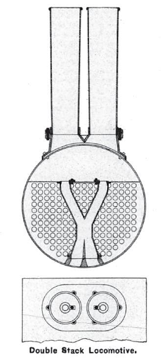 | | 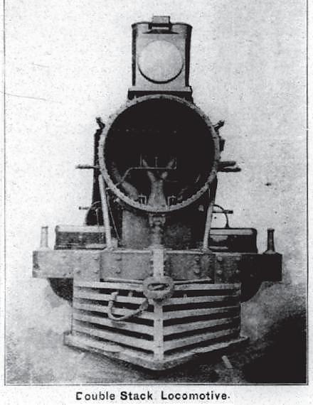
Above: A double-stack solution for the Toledo, Peoria & Western railroad, on a Rogers Consolidation locomotive.
This scheme was intended to improve the draught by equalising the flow through the central and outer fire-tubes. Trials showed that the amount of water evaporated per pond of coal was increased by 10%, and the miles run per ton of coal by 11%. However, these sort of improvements are so often obtained on carefully watched trials; W A Tuplin used to say that the coal consumption of any steam locomotive could be cut by 10% simply by painting the funnel blue. The design was patented by Mr W B Warren, the general foreman of the TP&W.
From American Engineer & Car Builder, approx 1896
|
The two stacks were separate, as shown on the left, but in the photograph, they are obscured by the headlight, and look as if they were trunked together.
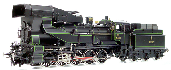 |
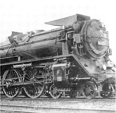
| Left: Model of a BR57 0-10-0 with air preheater: 1935
The picture shows a model by Micro Metakit of Number 57.305 of the Deutsche Reichsbahn. The BR57 0-10-0 series was designed for freight and heavy passenger trains. It was constructed by the Wiener Neustadt Lokomotiven Werke in 1922, and was originally the Austrian 80.4911. The locomotive is equipped with a exhaust gas heat exchanger to preheat the combustion air; this system was used between 1933 and 1937 and apparently gave good results. The locomotive is shown here as it looked in 1935, painted black with light-green lining and red drive rods.
Thanks to Ralph Brades and Robert Sumsion for bringing this locomotive to my attention.
|
The operation of the preheater looks straightforward- air enters the big aperture just in front of where the funnel would be, passes through a heat exchanger, and then is directed to the bottom of the firebox through the ducts on each side of the boiler. The exhaust gases leave by the angled spout above the boiler.
Information on this striking locomotive is hard to come by, and I have not yet located any pictures of a real BR57 with this fitting. Can anyone help?
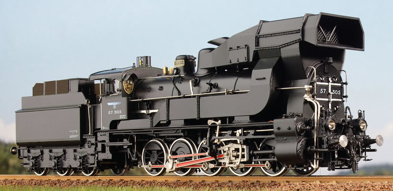 |
| Left: BR57 0-10-0 preheater from the other side: 1935
Shown here without the paint job. The side ducts can have done nothing to help forward vision, which looks like it was minimal. From this angle it appears that the air passed through horizontal tubes heated on the outside by the exhaust gases. One wonders about the effect on the draught.
Note the number 57.305 on the smokebox door and the side of the cab.
|
 |
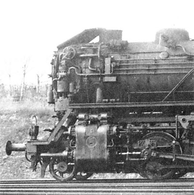
| Left: BR57 0-10-0 preheater in reality: 1935
This photograph is from 1935. The location and photographer are unknown.
|
 |
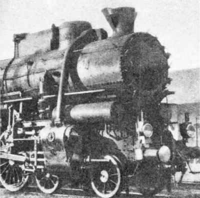
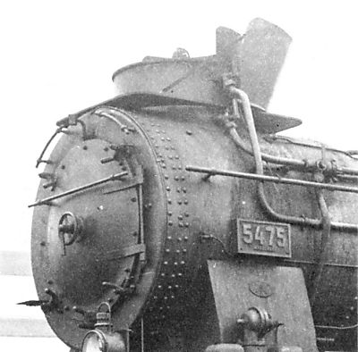
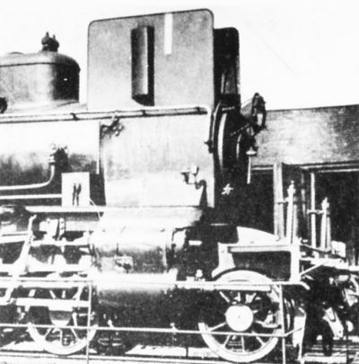
| Left: This 0-10-0 locomotive appears to have an enormous fat chimney: 1920-25
In fact it is a feed-water heater built around a chimney of normal dimensions.
Kurt Niederer tells me the loco is a modified Prussian G10. The "Reichsbahn" experimented on G10 5475 MAGDEBURG. (later 57 2008) MAGDEBURG 5475 was built in 1920 by Borsig, with works number 10761. As the "Reichsbahn" was founded on April 1, 1920, and the new numbers were applied from 1925/26, the experiments must have taken place within this period.
|
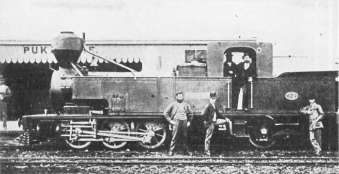 |
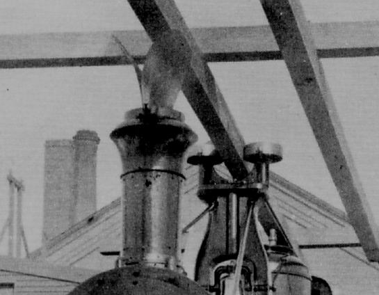
| Left: New Zealand Class-R Fairlie locomotive: 1879
According to The Locomotive for 15 Jan 1921, this single-ended Fairlie locomotive used a unique form of feed-water heating. Hot ashes were caught in the chimney and blown down into the side water tanks via the short pipes visible at each side of the base of the chimney, then ejected into the air through the longer pipes behind the chimney.
That is all the information available, and it sounds very strange. How were the hot ashes blown about? By steam? If the hot ashes were pushed through a pipe in the tank and then out again, it sounds as if very little heat transfer would take place, and the pipe would very easily get clogged with ash. It is not currently clear if this was a one-off modification or if all the R Class were so fitted.
If anyone knows more about this odd system I would be very glad to hear it.
|
A Fairlie locomotive has the driving wheels on a bogie so tight curves can be negotiated. The most usual was the double-ended Fairlie; single-ended Fairlies (also called Mason bogies) like this one were relatively rare.
STEALTH CHIMNEYS
 |
|
STEALTH
Left: Chinese stealth chimney
This is an armoured train used by the Chinese army, photographed near Ho-Nan. Photo date unknown. The chimney has been redirected to ground level in an attempt to dissipate the smoke and make the approach of the train less obvious.
The dustbin-like thing at the left is a rotating machine-gun turret.
See also Polish armoured trains, some of which had similiar stealth chimneys. Others had even stranger versions... see below.
|
 |
|
STEALTH
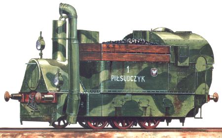
Left: The locomotive of the Polish armoured train "Saper"
A kkStB series 97 locomotive armoured in late 1918 by the Zieleniewski factory in Cracov. This locomotive was used in 1919 as part of the Polish armoured train P.P.17 "Saper".
The chimney opening seems to be facing forwards, which not have helped the draught. Unless the loco was designed to normally travel backwards?
Reproduced, by permission, from Michal Derela's superb armoured-train website:
http://derela.republika.pl/armtrain.htm
Do not miss!
|
 |
| STEALTH
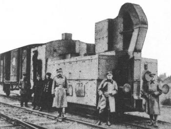
Left: Another armoured locomotive with a stealth chimney
Armoured locomotives series MAV 377 were the standard locomotives of Austro-Hungarian WW1 armoured trains. This captured MAV 377 powered the Polish armoured train "Pilsudczyk" during the Polish-Soviet War. (February 1919 - March 1921) Jozef Klemens Pilsudski was a Russophobic military hero who was chief of state of the newly reconstructed Poland.
It is not too clear how the original chimney connected with the down-pipe.
|
 |
| STEALTH
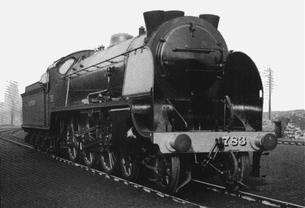
Left: Triple stealth chimneys
This was a stealth experiment by Bullied; the idea was to disperse the exhaust quickly to make the train less visible to enemy aircraft. There was no significant improvement and it was quickly removed.
The loco is 4-6-0 No 783 Sir Gillimere of the "King Arthur" class, on the Southern Railway in Great Britain.
Photographed in the mid 1930's. It was this photograph that inspired the colllection of unusual chimneys on this page.
|
SPARK SUPPRESSION
Above: The Adler locomotive of 1854 had a conventional chimney- unconventionally placed halfway along the boiler.
The Adler (Eagle) was one of two engines of the IIa (alt) Class on the Baden State Railway, one of the pre-unification German state railways. The design was intended for passenger and express duties. It is a Crampton locomotive; ie it has a single pair of drivers at the rear. This was a popular configuration in Europe until heavier trains made its lack of adhesive weight (you can see that most of the boiler is over the two non-drivng axles) all too obvious. The other engine was called Falcke (Falcon). Both were built by Maschinen-Gesellschaft-Karlsruhe (in German) in 1854.
The Adler had what was called a 're-entrant smokebox'. The firetubes ran to the front of the boiler as usual, but the combustion gases then doubled back over the top of the boiler to the base of the chimney. This apparently gave good spark-suppression, but at the expense of good steaming.
The Crampton layout, with the driving axle at the rear, allowed the cylinders to be halfway along the boiler and therefore conveniently placed for directing the exhaust up the chimney in the usual way. The two locomotives apparently lasted at least until 1875, but were rebuilt with conventional smoke-boxes and chimneys at some point before the final takeover by the state railway company. The dimensions can be found in Wikipedia though the article is in German.
Wikipedia has a List of Baden locomotives that includes these two locomotives.
The Crampton Locomotive M Sharman
Above: This monstrosity was another Crampton, and was built for the Camden & Amboy railway in the USA, in 1850.
The John Stevens shown above was designed by Robert Stevens, and dutifully named after his father; it was built by Norris Brothers. It was the first locomotive ever fitted with a six-wheel bogie; the next was in 1939, showing that this was something of a minority taste. The six wheels supported the boiler but left far too little adhesive weight for the rear 8-foot drivers. The locomotive was remodelled in 1856 and I can only hope it looked a bit less ugly afterwards. This is believed to be the oldest photograph of an American locomotive.
However, what concerns us here is the enormous chimney, designed to suppress sparks on the combustible grasslands of America. The two sideways projections at the bottom are for the removal of cinders.
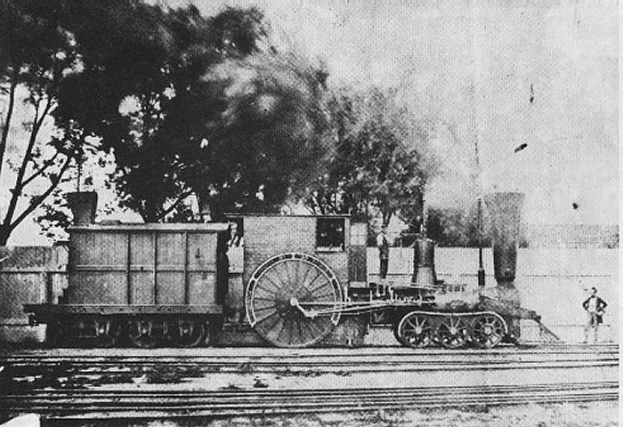 |
| Left: The John Stevens from the side
The spaces between the spokes of the drivers appear to have been filled in with wooden boards, presumably to reduce wind resistance. This was common practice on the flywheels of mill engines in England, but never used on British locomotives.
The U-shaped thing is a splasher that covers most of the circumference of the driving wheel.
|
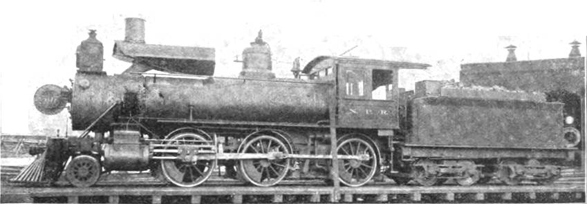
Above: A spark-arresting chimney for burning lignite on the Northern Pacific Railroad in 1899
This less than beautiful arrangement was invented by H H Warner, Master Mechanic of the Northern Pacific at Tacoma in Washington state, USA. One of their lines, about 300 miles long was handily adjacent to a deposit of lignite, which is particularly prone to emitting sparks and igniting the local scenery. It was described by Charles McShane in his classic book "The Locomotive Up to Date", around 1899.
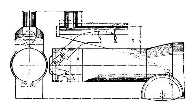 |
| Left: The internals of the Warner spark-arresting chimney
The blast pipe was curved backwards so the smokebox gases and sparks were blown into a spark chamber on top of the boiler, where they hit a near-vertical 'dash-plate' which can be seen in the drawing. The fragments of combustible material were allegedly extinguished by contact with the exhaust steam, and fell to the bottom of the chamber. From here they were conveyed back to the firebox through diagonal pipes that can be seen running above the wheel, urged on by suction maintained by steam jets where the pipes joined the firebox.
From "The Locomotive Up to Date" by Charles McShane, pp 440 - 442
|
According to McShane, the arrangement was not a one-off but was fitted to "a number of engines" and gave free steaming and fuel economy. Despite this the idea does not seem to have caught on in other lignite-burning areas. It clearly required plenty of load-gauge clearance above the boiler.
 |
| Left: Swedish spark-arresting chimney: 1888
This Swedish spark-arresting chimney consisted of a vertical sheet-iron section on top of a bulbous cast-iron inverted cone. There is a second internal cone around the blast-pipe nozzle, and this carries curved vanes that throw the cinders outwards, after which they drop down into the smoke-box for eventual removal in the usual way. It was "said to give very good results".
The small pipe coming in from the right is presumably the blower, used to create draught when the locomotive was stationary.
Dimensions appear to be in millimetres.
From The Railroad and Engineering Journal
Volume 62 Number 5, May 1888 pages 219 - 222
|
 |
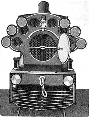
| Left: Boynton spark-deflecting chimney: 1889
The Boynton Bicycle Railroad was an experimental monorail system in which a tall and narrow locomotive travelled on a single steel rail, with an upper wooden beam, gripped by two rollers, to keep the locomotive upright. The deflecting plates shown here were fitted to prevent the beam catching fire.
The chimney was actually one of the less unconventional features.
From Monorails of the 19th Century
Adrian S Garner 2011
|
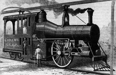 |
| Left: Boynton Bicycle Railroad locomotive: 1889
The concept was developed by Eben Moody Boynton between 1880 and 1886. An experimental monorail line was built on Coney Island, New York, and succesfully opened in October 1889. By June 1893 27,000 trains had run and 100,000 passengers had been carried safely. However the line did not recover the capital outlay and is believed to have closed later in 1893.
Note the two-storey cab with the fireman at the bottom.
|
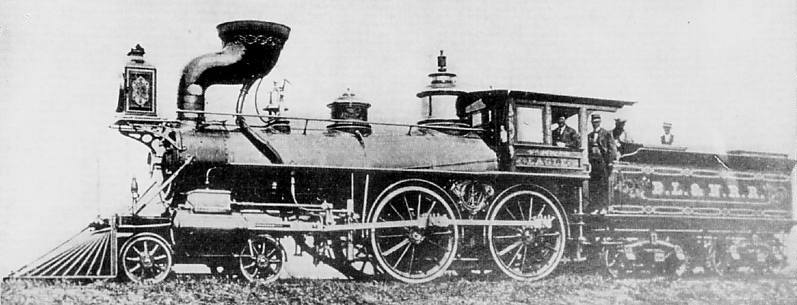 |
| Left: BL&NR cinder-catching chimney: date unknown
The Boston, Lowell, and Nashua Railroad came up with this startling design, strongly reminiscent of Sherlock Holmes' pipe, in an attempt to catch cinders thrown up the chimney.
From A Locomotive Engineer's Album
George B Abdill 1965
|
The locomotive is called "Eagle". Note the pipe running from the bowl, which directs the collected cinders down and under the middle of the boiler, and dumps them between the rails, a practice which cannot have done wooden sleepers much good. Other companies, such as the Colorado & Southern, with their "bear trap" chimneys, (see below) had pipes that directed the hot cinders to the outside of the track; that may of course have had the disadvantage of setting fire to vegetation beside the track instead. In theory at least the cinders were stored in a hopper behind the chimney until they were burnt out.
 |
| Left: C&S beartrap cinder-catching chimney: date 1940-1950
This is a Colorado & Southern narrow gauge freight train, leaving Waterton, Colorado, eastbound. The two engines are Baldwin type 2-8-0s engines (Nos 69 and 70) but only the lead engine has a "Ridgway Spark Arrestor", more commonly known as a bear trap stack.
From A Locomotive Engineer's Album
George B Abdill 1965
|
The Ridgway Spark Arrestor was a unique design by H W Ridgway, the C&S Superintendent of Motive Power. They were designed around 1917-1918, but not patented until 16 Aug 1921 as US Patent #1439262. By 1917 all C&S locomotives had been fitted with this form of spark arrestor. Presumably it looks like a bear trap in some way, but that is lost on me. If bears don't bother me, I don't bother them. The term "bear trap" was never used by the C&S itself, but was coined by the well-known rail enthusiast Lucius Beebe.
 |
| Left: The Ridgway patent: 1921
The gases and cinders pass up the conventional chimney 5. The gases pass through the mesh on the top at 2 and on the sloping front at 9, but cinders bounce off to the left and are held in the hopper at 10 and 13 until they have burned out. The flap 16 at the bottom of the disposal pipe is then opened and the dead cinders deposited.
|
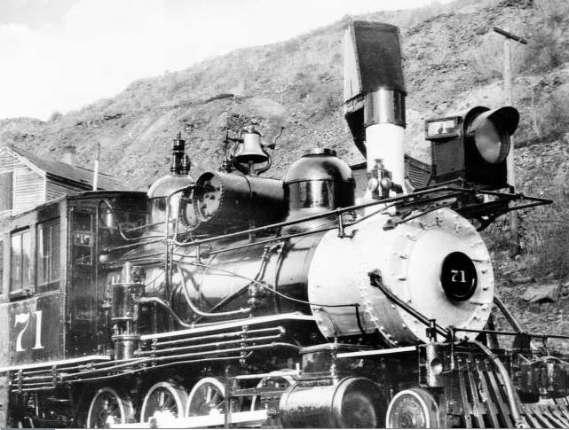 |
| Left: C&S beartrap chimney: date ??
A closer view of a bear trap chimney on Colorado & Southern No 71.
The pipe for cinder disposal runs down the far side of the boiler.
|
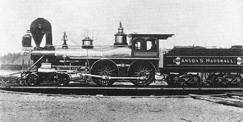 |
| Left: The Anson S Marshall: 1873
This remarkable locomotive is the Anson S Marshall, built by the Concord Railroad at their workshops in Concord, New Hampshire, in 1873. Cinders were to be caught and returned to the firebox for combustion, presumably via the square pipe at the right. Exactly how the cinders were to be induced to make this journey is unknown.
From A Locomotive Engineer's Album
George B Abdill 1965
|
According to Dr S R Wood, the invention was a failure. However, the locomotive (presumably refitted with a conventional chimney) was not scrapped until 1908. And who, pray, was Anson S Marshall? Google is your friend. He was a lawyer who opened an office in Concord in 1852. Presumably he went on to become a major shareholder in the Concord Railroad.
 |
| Left: Scheme for cinder disposal: 1897
This patented scheme was ridiculed by the journal that published it as "A Freaky Spark Arrester". The funnel at the front was supposed to take in air that would blow the cinders through a pipe which divided on top of the boiler and then passed to the rear on either side "to aid in ballasting the road bed".
From "Railway and Locomotive Engineering" Volume 10, No 11, Nov 1897, p858
|
It is difficult to imagine much steam being generated with such a restricted exhaust path. Perhaps the coffee-pot lid on top of the chimney, operated by a rope from the cab, was intended to give freer exit in case of need.
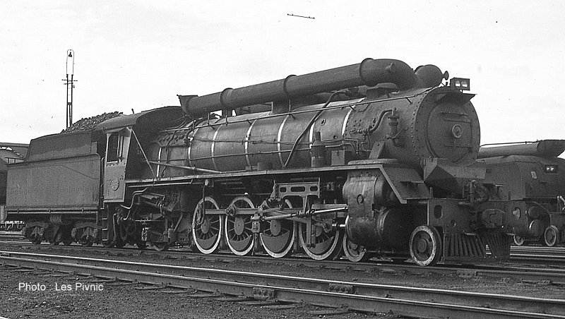 |
| Left: SAR 19C "Takbok": post 1935
This is a South African Railways (SAR) Class 19C locomotive (No 2456) which has been fitted with twin pipes leading backwards. While this should certainly have kept smoke and steam clear of the cab, its actual intended function was spark suppression.
Drawn to my attention by Nick Leverton
Photograph by Les Pivnic. Used by permission.
|
Despite its intended function, the pipework did not actually contain any sort of spark arrester. The comment was made by an SAR enthusiast and photographer that "Apparently the sparks were supposed to die of fright inside the long dark passages". "Takbok" is Afrikaans for "Deer"; no doubt the two pipes suggested horns.
The 4-8-2 19C's were fitted with rotary cam poppet valve gear; the drive shaft for this can be seen supported by a bracket from the frame. They were introduced in 1935.
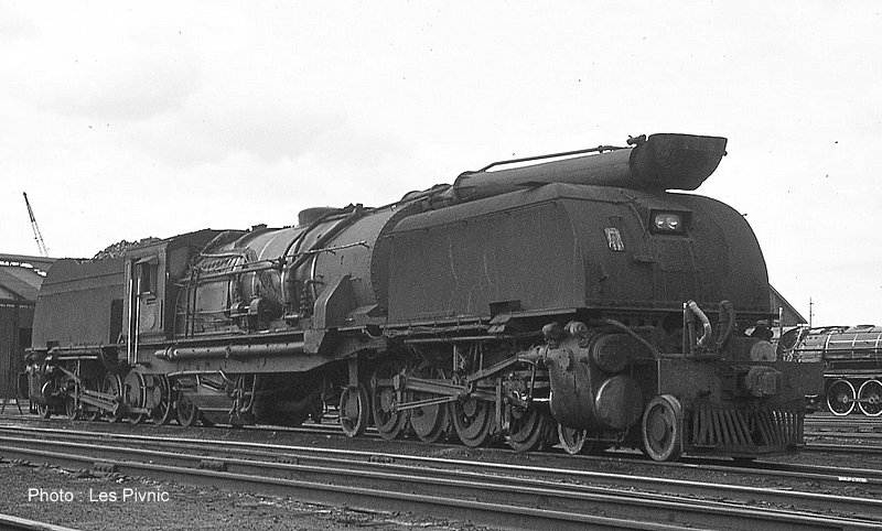 |
| Left: SAR Class GEA Garrett "Renoster" No 4009: 194?
This is a South African Railways (SAR) Class GEA 4009 Garrett converted with a long tube swept forwards and up over the leading articulated water tank; once again no actual spark arrester apparatus was fitted. Presumably the tube was connected to the boiler by some sort of flexible coupling.
Drawn to my attention by Nick Leverton
Photograph by Les Pivnic. Used by permission.
|
It is believed it was later converted to a two-outlet arrangement like the 19C above. These locomotives were designed by Dr M M Loubser, Chief Mechanical Engineer of the SAR, and built by Beyer, Peacock and Company. "Renoster" is Afrikaans for "Rhinoceros", suggested by the upward curve of the front end of the pipe.
According to Google, photographic evidence exists showing that "stove-pipe chimneys" were also fitted to examples of the following SAR classes: 16DA wide firebox, 16E, 19A and HF. The Museum staff have have found nothing so far.
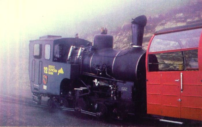 |
| Left: Brienz-Rothorn locomotive
This steam locomotive operates on the Brienz-Rothorn Railway, a tourist rack railway in Switzerland. The BRB climbs from Brienz to the top of the Brienzer Rothorn. The railway is 7.6 kilometres (4.7 miles) long, and is built to 800 mm gauge (2ft 7.5in gauge), using the Abt double rack system. Most trains are operated by steam locomotives.
Part of the line is in tunnel, and hinged chimney caps are used to protect the tunnel roof from cinders. This one is operated from the cab by means of a Bowden cable. Note the two water level gauges outside the cab.
|
THE CHIMNEY CRANES
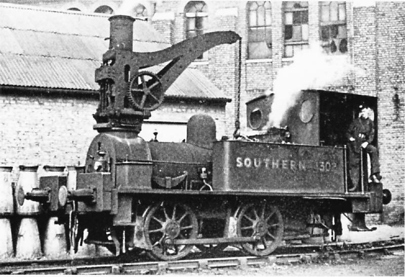 |
| Left: South Eastern Railway crane locomotive; 1951
Surely a strong contender for the title of "Oddest Chimney".
This is a South Eastern Railway 0-4-0 tank engine with a steam -powered crane fitted around the chimney., and is pictured standing at Stewarts Lane motive power depot in June 1946.
From The Railway Magazine Oct 1951
|
The crane hoisting power was provided by a small vertical steam engine that can be seen to the left of the funnel. It is not clear from this photograph if the engine had one or two cylinders, but two is more likely as this would prevent problems with the engine stopping on a dead centre. The engine crankshaft is coupled to another horizontal shaft, apparently by bevel gears, and there is then a worm drive to the large gearwheel, whose shaft carried the hoisting drum.
This crane locomotive was built by Neilsons in 1881. They were were no strangers to unusual locomotives; see The One-Cylinder Locomotive.
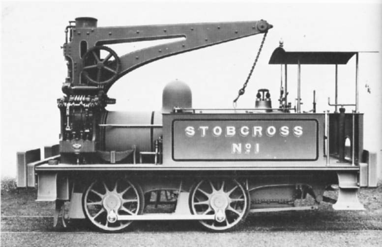 |
| Left: Nielson chimney-crane locomotive: 1875
This is not the same locomotive as pictured above. There are now two small two-cylinder steam engines operating the crane. One is mounted on the front of the chimney as for the loco above, and is for hoisting. A second small engine at the side of the smokebox appears to be connected to a large horizontal gearwheel for slewing the jib. The design of the jib is different. This is a Nielson works photo dating from 1875.
UD
|
The Stobcross Railway was a freight line in the west of Glasgow that gave access to the new Queens Dock. It opened in 1874, and presumably by 1875 they decided they needed a mobile crane.
FOR REASONS UNKNOWN
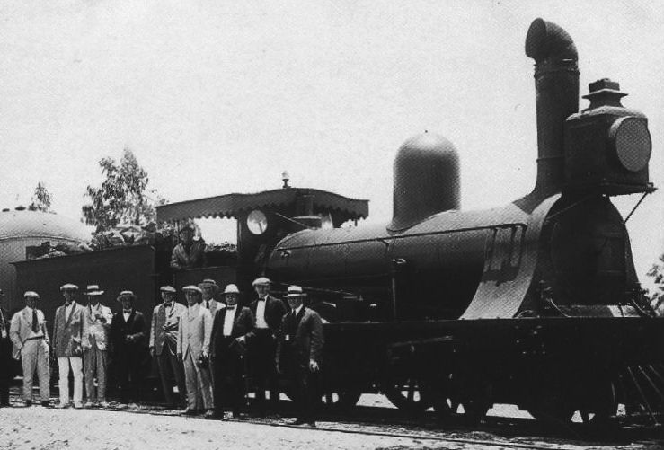 |
| Left: This South American 4-4-0 locomotive had a cowled chimney
It is pictured here at the head of a tourist train between Tocna and Arica, in the desert Tacna territory, which was disputed between Peru and Chile until 1930. The motivation for the cowl is unknown; possibly it was meant to throw the smoke sideways away from the cab.
|
 |
| Left: Kitson-Meyer No 3348, under restoration in 2013
This picture suggest that cowled chimneys like this were a South American thing. The cowl here is pointed forwards rather than sideways; surely that would not be helpful for steaming. It looks on close examination as if the cowl is hinged to tilt forward; it is not clear if it can rotate. Note the cylinder sticking forwards out of the chimney; this may be a hydraulic actuator.
This is Kitson-Meyer No 3348, an 0-8-6-0 articulated rack tank engine built in 1909 for the Transandino RR, pictured on 8-Sep-2013 at Los Andes Station workshop, Chile. At the time of the picture, this locomotive was under restoration to working order by a group of volunteers.
|
 |
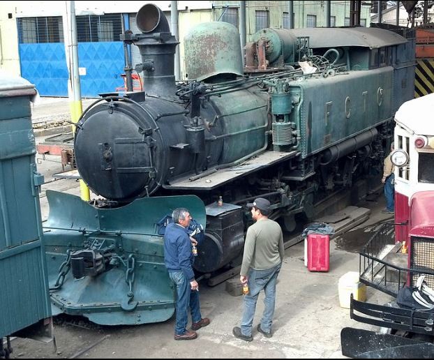
| Left: Kitson-Meyer No 3349 pictured in Jan 2019
The chimney cowl here is again pointed forwards rather than sideways, which remain puzzling. There is again a small cylinder sticking out horizontally from the front of the chimney.
Here Chilean Transandine Railway (Ferrocarril Trasandino Chileno = FCTC) Type Z Kitson-Meyer metre-gauge 0-8-6-0 articulated rack tank engine No 3349 rests on an ex-Chilean State Railways (Ferrocarriles del Estado = FFCC del E / EFE) 5'6" broad-gauge turntable at the Santiago Railway Museum in Quinta Normal Park, Santiago de Chile. Like 3348 it was built by Kitson in 1909.
Three Kitson Meyers of the Transandine Railways have survived, one in Argentina (Tafi Viejo; as of 2013 derelict) and two in Chile (#3348 at Los Andes station workshop, seen under restoration on 8-Sep-2013 and Serial #4664 Operating #3349 at the Museo Ferroviario de Santiago, Parque Quinta Normal, Santiago de Chile, cosmetically restored)
|
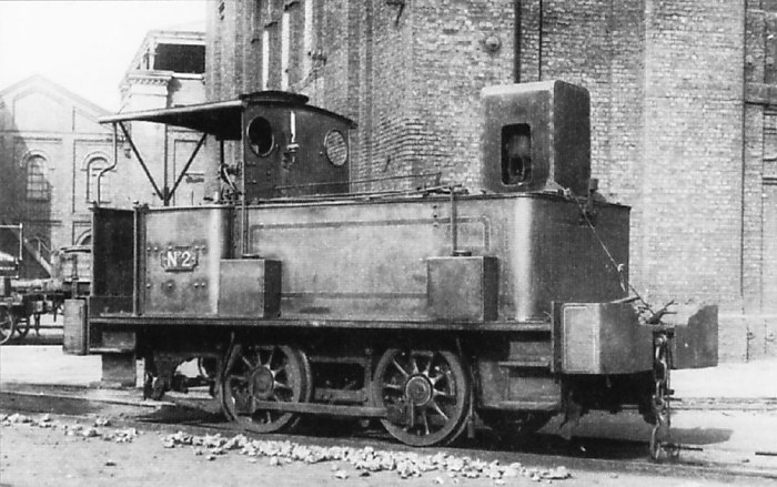 |
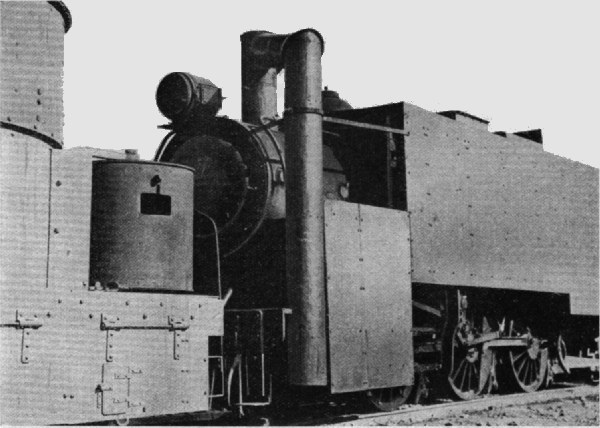
| Left: The Beckton Shoebox: 1927
Another contender for 'Strangest Chimney' is this locomotive which kept its cylinders in its 'chimney'. This peculiar looking machine started life as a conventional 0-4-0 well tank engine No 1562 in 1870, when it was delivered to Beckton Gasworks which were variously described as "The largest gasworks in Europe" or "The largest gasworks in the world".
|
After many years work, in 1927 it was rebuilt as a vertical-boilered locomotive using Sentinel technology, and was renumbered as No 6951. Sentinel locomotives had vertical-cylinder steam engines that were geared-down and drove the wheels via chain or shafts, the technology being derived from Sentinel steam-wagons.
In this case the square 'chimney' at the front is actually a cover for the two-cylinder vertical steam engine. The real chimney is a very squat affair protruding through the cab roof at its front; the vertical boiler, also a rather squat item as wide as it was tall, is inside the cab, just behind the spectacle plate.
The rebuild was not a success, being less effective than the original design. (An unmodified sister engine, No 1561, was available for comparison at Beckton) The locomotive crews called it 'The Shoebox' and did not like it. It was not much used before being disposed of (and presumably scrapped) in 1938.
In other fields Sentinel locomotives were very successful as shunters and tramway engines.
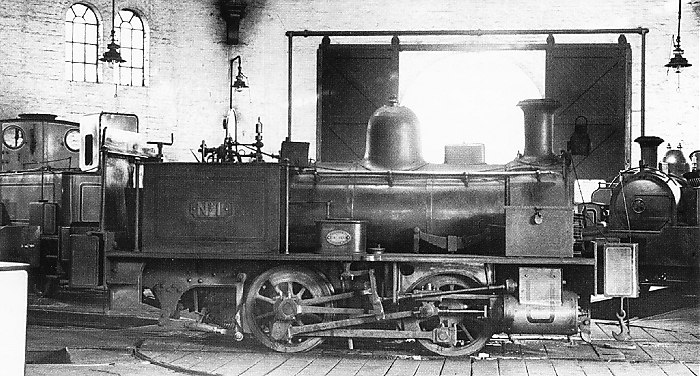 |
| Left: The Beckton Shoebox: 1927
The Sentinel conversion can be seen at rear left. In the foreground is the unmodified sister engine No 1561, demonstrating how radical the rebuild was; only the chassis and the wheels were retained.
|
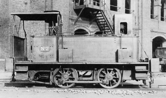 |
| Left: The Beckton Shoebox: 1927
This view of the unloved Shoebox shows the chain drive to the rear axle. From the angle of the chain there must have been at least two shafts between the engine crankshaft and the chain sprocket.
The real chimney can be seen just to the left of the spectacle plate.
|
Bibliography:
"The British Steam Railway Locomotive" Vol I, E L Ahrons. Pub Ian Allan.
"The Complete Book of Locomotives" Colin Garratt


