The locomotive displayed in this gallery never existed, and its design was an unnatural mixture of at least two real locomotives. I have therefore decided to call it The Chimera. One locomotive was designed by M. Thuile, originating a cabforward locomotive. The trials of this locomotive were ended when Thuile was killed in an accident in June 1900. The other locomotive that seems to have contributed to its design was the big Heilmann, which appeared in 1897.
The article describing it was called 'Thuile and Foure’s Locomotive', and it appeared in the The Engineer for 30 Sept 1898, p331. It says the locomotive was designed 'some years ago', and that the information came from the Bulletin of the International Raiway Conference. (No date given)
The design is only vaguely described in the text of an Engineering article but the drawings are precise. Thuile and Foure took out US patent 646,821A, simply titled 'Steam boiler' in April 1900; the design is not the same as in the drawings in The Engineer. The inventor's names are given as Emmanuel Foure And Henri Thuile, Of Alexandria, Egypt.
 |
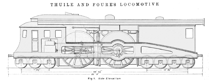
| Left: Side elevation of the Thuile and Foure Chimera locomotive: 1900
This shows a cabforward design with a separate stoking cab at the rear. Given the 6-4-8 wheel layout, it is questionable how much adhesion weight was available for the driving wheels.
The front of the locomotive looks very like that of the big Heilmann.
|
 |
|
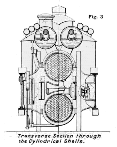
Above: Transverse section of the Thuile and Foure Chimera locomotive: 1900
This shows that there were actually two boilers, connected by three big tubes, with the driving axles passing between them. This was not a unique idea; the Aigle locomotive of 1855 had its main axles passing over the low-set boiler and under the upper steam drum.
Above the top boiler are what appear to be two steam drums (steam reservoirs) each connected to the top boiler by three large tubes. Actually they were half-filled with water, as the level above the firebox shows.
Note the water-filled arch in the firebox; just to its right is a water-cooled wall that presumably controlled the distribution of the hot gas between the two boilers; it does not look as if the top boiler was going to get much of a share. The upper boiler tubes appear to be completely inacessible from the firebox end, so if you needed to expand the tube ends in the boiler end-plate to stop leakage, you would have had quite a problem on your hands.
Boiler tubes need to be cleaned; those of the top boiler could be accessed from the front, but the tubes of the lower boiler appear to be inacessible from either end.
|
 |
| Left: Transverse section of the Thuile and Foure Chimera locomotive: 1900
This shows the two boilers and the two steam drums, each with pipe arrangements to pick up the steam, but no steam domes. The 'steam drums' are shown as actually being half-full of water. Priming, anyone?
There appear to be three large pipes mounted on each side of the roof. On the side elevation they project beyond the rear of the locomotive; their purpose is currently unknown.
|


