Gallery opened: Oct 2003
Updated: 9 Feb 2009
Better sideview picture
Boiler cross-section added


Big Wheels in France: L'Aigle |
Gallery opened: Oct 2003 |
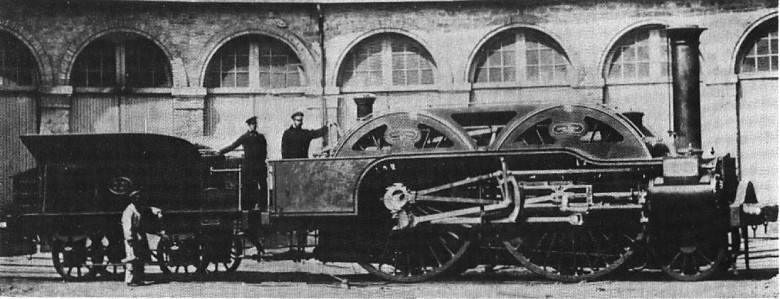 | Left: The "L'Aigle" proudly displayed. So far as I am aware, this is the only photograph existing.
|
L'Aigle (The Eagle) was designed by M Aimé-Etienne Blavier and M Larpent for the L'Ouest railway, where it carried No 261. It was built in Batignolles by Gouin et Cie in 1855 and in that year appeared at the International Exhibition in Paris.
L'Aigle had the largest wheels ever fitted to a French locomotive at 9ft 4in. (The world record of 10 feet is apparently held by The Hurricane. In view of the inglorious results from locomotives with enormous wheels, this is not a record to aspire to)
This locomotive was intended to run at twice the speed of the Crampton, or to have pulled a 100 ton load up a 1/100 incline at the same speed as the Crampton could on the level, depending on which account you believe. There appear to have been some vague claims floating about that L'Aigle had reached- or was capable of reaching- 160 km/hr (100mph) but this seems extremely doubtful. 160 km/hr was not officially reached in France until 1889.
Accurate information is in short supply, but the loco is known to have used Stephenson valvegear, and had cylinder dimensions of 16.5in bore by 22in stroke.
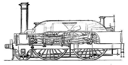
L'Aigle had a rather peculiar arrangement for raising steam. With such huge wheels, the axles came too high for a normal boiler to be placed between the frame members, and so a boiler with two parts was used, the driving axles passing between the two. The upper section was connected to the lower by two large diameter pipes. These apparently had joints that caused maintenance problems.
The boiler capacity proved to be quite inadequate and L'Aigle never turned a wheel in revenue-earning service.
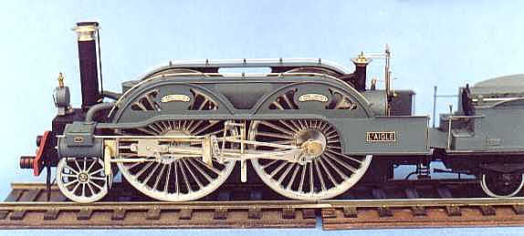 | Left: A fine model of "L'Aigle" by Martyna. Picture used by permission. See more at http://martyna.com (Site is in French)
|
 | Left: Side elevation of "L'Aigle".
|
 | Left: Two cross-sections of the Aigle boiler.
|
![]()

|