Gallery opened: Nov 2001More on recent research at Southampton |
Before electronic amplification became practical, the volume obtainable from gramophones was strictly limited. Here are some early efforts to do something about it.
There is now a page on compressed-air gramophones in Wikipedia.
![]()
EDISON'S AEROPHONE: 1878.
Thomas Edison appears to have been the first to use a compressed air amplifier, both to overcome the problem of lack of replay volume for his phonographs, and to amplify the human voice. They appear in a British patent he took out in 1878. The idea of Short and Parsons did not emerge until twenty years later.
NB: In common usage an 'aerophone' is a musical instrument that produces sound mainly by causing a body of air to vibrate, without using of strings or membranes.
 | Left: Not Edison's Aerophone: 1878
|
 | Left: Edison's Aerophone patent: 1878
|
 | Left: Edison's Aerophone patent: 1878
|
 | Left: Edison's Aerophone: 1878
|
 | Left: Not Edison's Aerophone: 1878
|
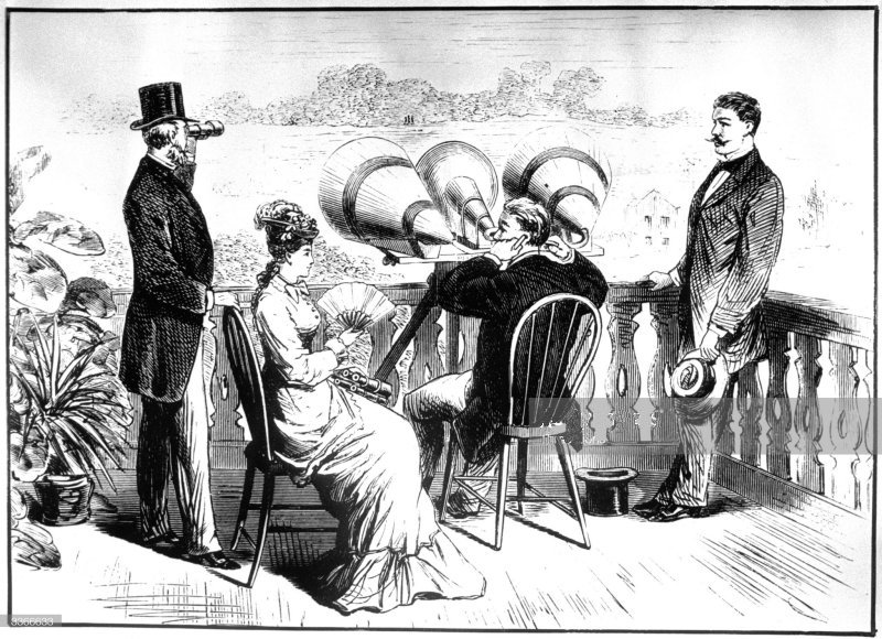
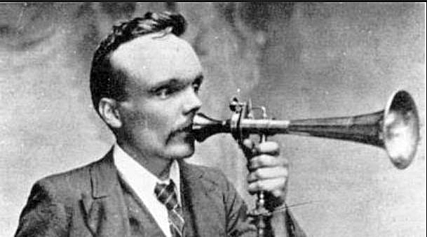
 | Left: The Gouraudphone in an English newspaper: 1900
|
THE AUXETOPHONE: 1898-1918.
Two Englishmen, Horace Short and Sir Charles A Parsons (yes, the steam turbine man) introduced the compressed air amplifiers known as Auxetophones. Horace Short began the development of the idea and was granted a patent in 1898, and again in 1901. The patent rights were sold to Parsons in 1903. Parsons, who was noted for his skill as a craftsman, took on the development of the Auxetophone as a hobby when he was already financially secure from his steam turbine business, and applied it to musical instruments as well as gramophones.
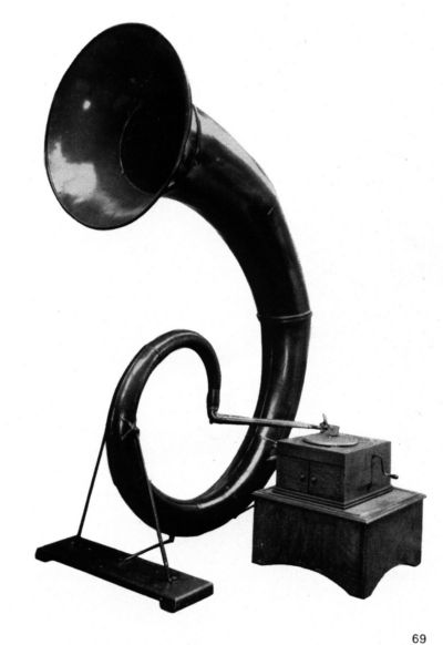
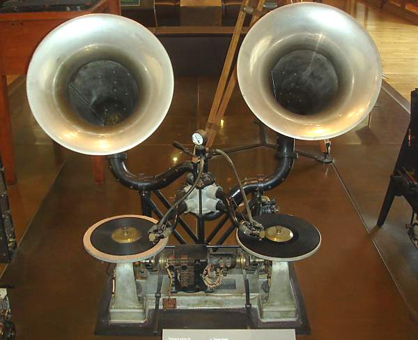
 | Left: The dreaded Auxetophone ready to open fire on a defenceless audience.
Air pressure was provided by a 1/6 horsepower electric motor, and particles were removed from the air by what appears to have been a sort of oil-bath filter, as once used on cars. Clearly the aierophone rol valve would have been susceptible to dirt and fluff. One of the problems seems to have been the absence of any kind of volume control; probably some sort of air-pressure regulator would have worked. No technical details seem to be available on its distortion performance, but from the comment above it was probably pretty bad. Go to http://www.youtube.com/user/ReneRondeau (external link) and select the Victor Auxetophone video. The volume also does not seem as devastating as claimed, but this is hard to judge as the recording equipment used to make the video probably had some sort of automatic level control. |
Horace Short was one of the brothers who founded the Short aeroplane manufacture business, which still exists in Belfast. See http://www.ctie.monash.edu.au/hargrave/short.html (external link)
Short was granted British Patent No 22,768 (granted 23rd September 1899)covering his development of the Auxetophone.
I have found a brief reference that says: "1898: The compressed air Auxetophone is first used to broadcast records of operatic arias from the tops of the Blackpool Tower in England and the Eiffel Tower in France." This was one Short's first prototypes; it gives you an idea of just how loud this thing could be.
A Short Auxetophone was heard all over Paris during the 1900 Paris Exposition, when it bellowed out Edison phonograph recordings from the top of the Eiffel Tower.
 | Left: One of Short's patents
|
 | Left: One of Short's patents: 1901
|
 | Left: Horace Short holding the valve assembly of an auxetophone: date unkown
|
In 1903 Short sold the patent rights to Parsons, and that year another British patent (No 10468) was granted, following Sir Charles' improvements to the air valve, the critical part of the system. In a letter written in 1921 to Sir Ambrose Fleming (The inventor of the thermionic diode valve) Parsons says:
"I worked at this subject as a hobby in my workshop at home and tried many types of valve- double-beat, slide-valves with multiple openings, then a form of valve made of sheet metal on edge like a fireworks cracker, and lastly the "comb-valve"- much the best because it delivered a flat-faced sound wave into the trumpet and it is not liable to be impeded or struck by small particles of dirt. It is similar to Short's. I made valves of comb pitches from 1/50 of an inch for reproducing from faint phonograph records, up to some of 1/4 inch pitch for attachment to double-bass stringed instruments. The very fine ones were made of hard gold, the rest of magnalium.* The air-valve reproducer was shown at the Royal Society about 1904, on a gramophone. Professor Johnston Stoney, FRS, was much interested, suggested the name "Auxetophone", and treated the matter mathematically.
If the motion of the valve is expressed in a series of sine terms (Fourier) the the sound wave produced is the first differential, and consequently the harmonics are much increased in amplitude above the fundamental, and the tone much increased in richness. This was found to be the case when used on the gramophone or when actuated from the bridge of a stringed instrument.
It was shown soon afterwards in the Library of the Royal Institution and notices appeared in the papers, and then Short's letter reached me. Previously I had not made any patent search and was not aware of his patent. Edison's had either been cited by the Patent Office or Marks and Clerk had known of it.
It appeared that Short had played an instrument on the top of the Eiffel Tower some years before. He (Short) was at that time connected with Colonel Gouroagh of the Edison Company, but when I met him he had very little money and readily assented to sell his patent to me for �700 down, and an agreement for four years at �400 per annum. Soon afterwards, the Gramophone Company of 21 City Road bought mine and Short's rights for gramophones and phonographs for all countries for �5000. I retained the rights for musical instruments.
The valve you have (taken to pieces) was made by Short in our Shops (at Heaton) and was played on a double-bass at the Promenade Concerts at Queen's Hall all one winter about 1906.
We spent much time and money in endeavours to introduce it on violins, 'cellos, and double-bass instruments, but were virtually blocked or boycotted by the Musical Fraternity, because they found it would reduce the number of executants from one-fifth to one-tenth for the same volume of sound. I dropped the whole matter, and Short was employed on other work including experimental attempts to make diamonds. He left our service about 1914 to join his brothers making sea-planes, and he died in about 1917, leaving �70,000, having made large profits from the Short Folding Wing Sea Plane.
The limiting factor to greater magnification of sound by means of an air-valve seemed to be viscous resistance in passing through minute apertures. Experiments showed that this was very marked below 1/1000 inch aperture. Hence there results a limit to the fineness of the comb. I was never able to obtain an actual magnification of the voice by means of an air-valve, Your (Fleming's) ionic valve has solved this problem."
* An alloy of aluminium and magnesium.
This letter appears to indicate that Parsons was interested in compressed-air amplification and developed the comb-valve before he bought Short's patent, which shows a different kind of valve. Perhaps it was the patent on the general principle, rather than the details of the valve technology, which Parsons wished to acquire.
It also raises the question of whether Short's voice-amplifier actually worked; Parsons says he could not make one that worked. Note also that Parsons does not seem to appreciate that one amplified double-bass is not remotely the same thing as five basses playing in chorus. And one can hardly blame musicians for being unenthusiastic about an invention intended to put most of them out of work.
How exactly did the air-control valve work? Since sound consists of positive and negative pressure changes, you might imagine that while the machine was "quiescent" there was a steady flow of air which was increased for positive excursions and decreased for negative ones. If this was not the case- and this point currently remains obscure- then the sound waveform would have been half-wave rectified, which would explain the poor sound quality. The supply of air to both sides of the tonebox may be related to this, or it may be to do with balancing the valve to reduce the frictional forces on it.
Later versions of the air-valve introduced partial balancing so that the relatively small needle forces could better control the pressurised air. A spring-loaded piston powered by the air supply acted on a wire-spring lever attached to the valve cover.
Parsons' first experimental air-valves had combs made of boxwood, the slits being cut with a jeweller's saw. The air pressure used in early tests was 2 to 3 psi.
Despite Parsons' and Short's efforts, the subjective results were apparently still somewhat short of perfection. One reaction from an Edinburgh journal was:
"Have you heard the auxetophone? It is to be hoped not. All Mr. Parsons' turbines will be wanted to take long-suffering humanity out of earshot of his diabolical invention".
The following letter was sent on 18th May 1909 by Sir Henry Wood, who co-founded the Promenade concerts in 1895:
"Dear Mr Parsons,
I am making a new orchestral arrangement for next season's Promenade Concerts at Queen's Hall of Wagner's "Siegfried" and I particularly want to do the scene with the Dragon's voice.
On the stage, this is always sung into a very large megaphone, but in my arrangement I want to do it on a very big bass tuba. do you think it would be possible for me to utilise your auxetophone? Of course I have never heard a tuba reinforced by your splendid invention, but perhaps during June, when I shall be fairly free, you could arrange for me to bring my player down."
Unfortunately nothing came of this innovative proposal, for Sir Henry wrote in the following June:
"Very many thanks for your kind letter. I had hoped to be able to the Royal College on the day you suggested, but was prevented. I now find that a bass tuba played into an ordinary very large megaphone (which I am having made by Hawkes*) gives the desired effect. With kind regards and many thanks..."
* Who went on to become part of the famous musical company Boosey & Hawkes.
A Victor auxetophone-gramophone was demonstrated to the public in November 1906 at a Trade Exhibition at Earl's Court. Mr S H Sheard recalled that the correct operating pressure had not yet been determined:
"We used about six or seven pounds to the square inch, with the rather amusing result that those of the audience who took the front rows of chairs very quickly clapped their hands to their ears and made their way to the back of the building. It was subsequently found that a pressure of not more than two-and-a-half pounds to the square inch was adequate." Which if nothing else proves that varying the operating pressure was a viable way of altering the volume.
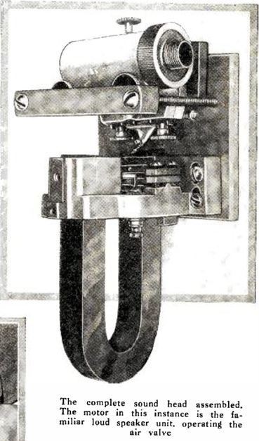
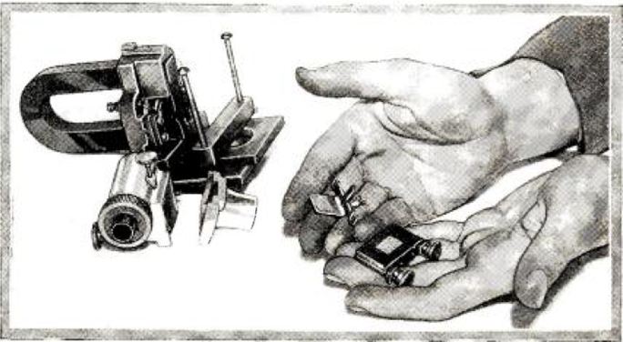
In 1922-23, when wireless broadcasting had become established, the long-neglected auxetophones were resurrected at Parsons' Heaton works by Mr A Q Carnegie, one of Parsons' colleagues. A gramophone-type valve was driven by a magnetic motor, producing a high-volume output at a time when the capabilities of electronic valve amplifiers were very limited. The idea was not however pursued, one reason being that the patents had expired and this would limit the profitability of future business. The loudspeaker was still in use at the Heaton works in 1933.
Parsons took out three patents in all:
No. 10,468 (1903) Improvements in Sound Reproducers or Intensifiers applicable to Phonographs, Gramophones, Telephones and the like.
No. 10,469 (1903) Improvements in and relating to musical instruments.
No. 10,892 (1904) Improvements in and relating to Reproducers or Resonators for Gramophones, Phonographs and the like.
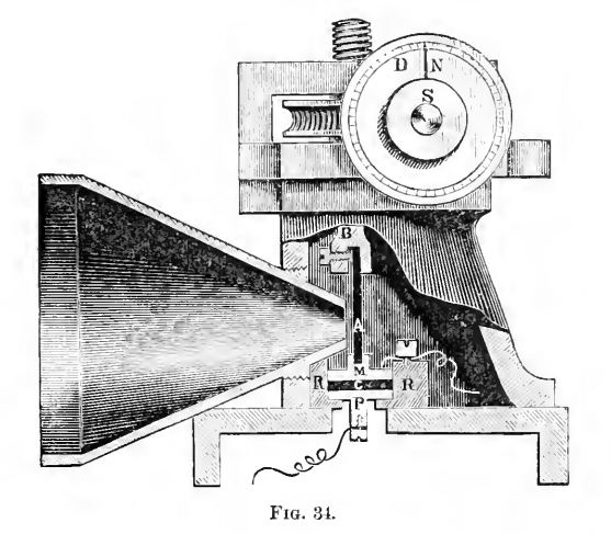
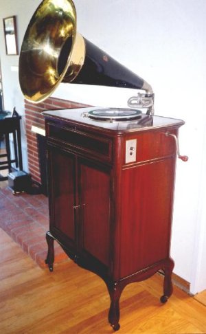
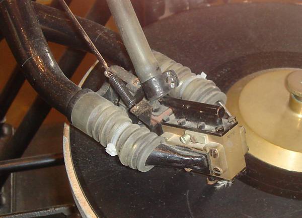
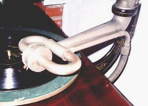 | Left: Close-up of the Victor machine pictured above, showing the tonearm, carrying the air-control valve.
|
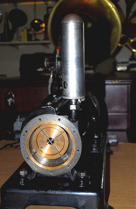
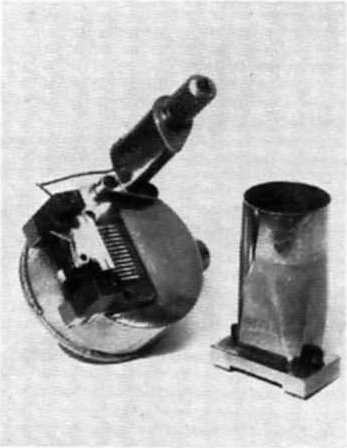
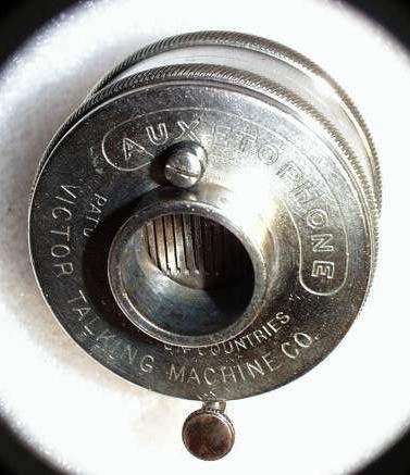 | Left: A close-up of the Victor valve box, showing the air-control comb valve. The thumbscrew at the bottom is to secure the gramophone needle. The screw at the top presumably adjusts the air valve.
Air was supplied to the input side of the combs, but some of the pressurized air was also fed to the horn (or output) side. The force holding the comb valve down when the groove of the record had not moved the needlebar was supplied by the slight overpressure on the horn side. |
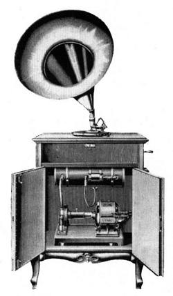
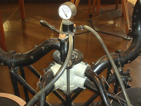
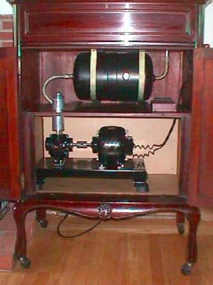 | Left: Inside the Victor.
No cutout switch to prevent over-pressurisation is visible, but it might have been housed in the plinth at the top, where the motor wires appear to go. One hopes there was at least a safety-valve. The working pressure was only 2.5 psi. Note rubber mountings for the motor-compressor assembly. This machine is owned by Rene Rondeau. |
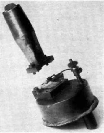
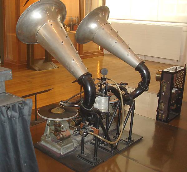
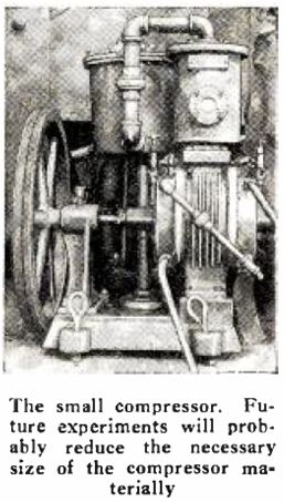
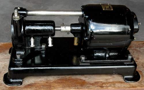 | Left: The compressor of the Victor Auxetophone seen at the top of this page.
http://www.montanaphonograph.com/gallery/Auxetophone.html |
 | Left: The compressor of the Victor Auxetophone seen at the top of this page.
|
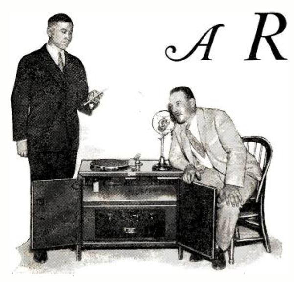
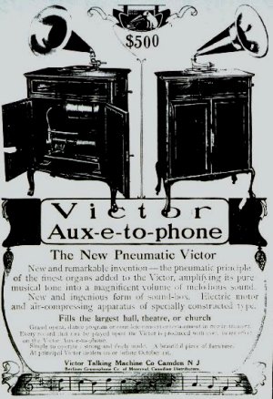 | Left: The Auxetophone was manufactured by Victor from 1906 ("the New Pneumatic Victor") until 1918.
Auxetophone sales literature promoted its use in "large residences" but the real market appears to have been restricted to open-air cafes in parks and similar, despite the need for an electricity supply. Dance halls, theaters, and restaurants typically hired small or large bands, and there is not much doubt that their music sounded much better.
|
 | Left: This appears to be an early model Auxetophone, possibly a prototype.
The following listening report was kindly provided by Dan Gilmore: |
I understand that a picture of the auxetophone connected to a cello during the performance of a concerto with full orchestra is shown in the C A Parsons Co. Heaton Works Journal for December 1934. (Volume 1, No 6) I have no idea what an Auxetophoned cello sounded like; we can only be confident that it was LOUD.
 | Left: Early model of the Auxetophone valve for gramophone use.
|
 | Left: Standard model Auxetophone with upper part removed to show the valve grating.
|
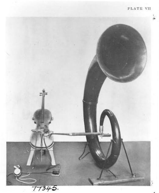
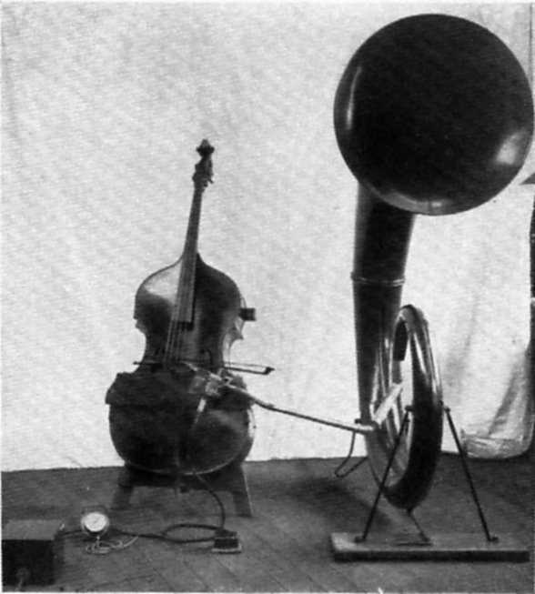 | Left: A double-bass fitted with an Auxetophone.
|
 | Left: A cello fitted with an Auxetophone.
|
I received the following message from Mr Ted Bowman in December 2013:
"In the 1920's my late father constructed a loud-hailer for use at Woolsington airport (now Newcastle airport) which enabled voice communication from the ground to pilots flying overhead. This consisted of a Parsons Auxetophone in which the air valve was actuated by a "reed" earphone. At that time my father earned his living building custom-made radio receivers for wealthy Northumbrians."
On a website devoted to the London tube system, there is said: "More than one attempt has been made to encourage considerate behaviour on escalators; an attempt was made, for example, in 1920 using a kind of compressed air amplifier that took a signal from a gramophone recording to bawl out 'Stand on the Right'. I have not so far been able to find out any more about this.
Bibliography: "Charles Parsons: His Life and Work" by Rollo Appleyard. Constable & Co Ltd, 1933.
![]()
OTHER APPLICATIONS: 1903
In 1903 in Germany Oscar Messter patented his new Auxtephone system which used compressed air amplifiers to feed special loudspeakers. No more details known at present.
![]()
 | Left: Pathe compressed-air gramophone.
|
![]()
COMPRESSED AIR IN THE CINEMA: 1907
George Kemp recalls:
"We had talking pictures in 1907. The film was run through the machine and it had a gramophone with it. The sound was amplified by compressed air. You had a blower which went into one of those trumpet things and the idea was to get the film and the gramophone to synchronise with each other, which wasn't always easy." |
Source: Pictures Past by Janet McBain. Moorfoot Publishing, Edinburgh 1985.
Twenty years before the �talkies�, the Panopticon advertised a variety of sound-film devices. First came Gaumont�s chronophone, which A E Pickard claimed was shown in Glasgow a day before London. A couple of years later, the theatre acquired another version of this technology, the auxetophone � so for a month or so in 1908, the Panopticon programmes included silent films on the bioscope as well as song films in the other two systems.
The very first valve amplifiers did not appear until 1906.
![]()
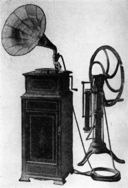
THE FORTOPHON STARKTONMASCHINE: 1908?
 | Left: The Fortophon Starktonmaschine.
|
![]()
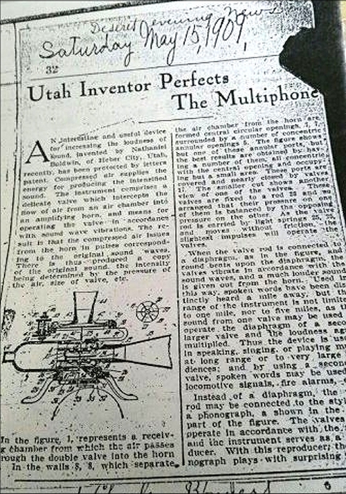
THE NATHANIEL BALDWIN MULTIPHONE: 1910
 | Left: The Nathaniel Baldwin Multiphone: 1910
|
There is no sign that the Multiphone was developed further. There was nothing very novel about it.
There is some info on Nathaniel Baldwin on his Wikipedia page.
There is much more information here. Baldwin was a Mormon, (LDS) who came to be at odds with their leadership when he continued to argue for polygamous marriage when the LDS had (officially) abandoned it. Despite this, he only married once. He attended a conference of the LDS, and was struck by how hard it was to hear speakers in distant parts of the Salt Lake Tabernacle. As he later said: "...until that day nothing was further from my mind than the problem of amplifying sound. But, after that day, the thought could not be pushed into the background." At the time he was working as an electrician and air compressor operator at the Mountain Lake mine; compressed air was to hand.
 | Left: The Nathaniel Baldwin Multiphone: 1909
|
 | Left: The Nathaniel Baldwin Multiphone: 1909
|
 | Left: The Nathaniel Baldwin Multiphone: 1910
|
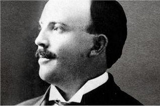 | Left: Nathaniel Baldwin: date unknown
|
![]()
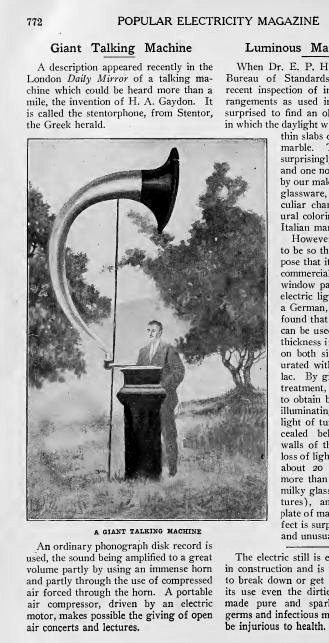
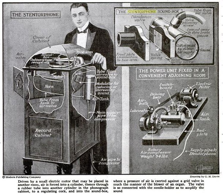
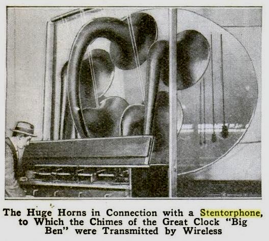
THE STENTORPHONE: 1910-21
 | Left: The Gaydon Stentorphone: 1912
|
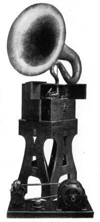 | Left: The Gaydon Stentorphone:1914
|
 | Left: The Stentorphone in Popular Science: 1921
|
'Stentorphone' was also used as the name for a particularly loud pipe-organ stop.
 | Left: The Stentorphone in Popular Mechanics: 1921
|
![]()
THE GAUMONT CHRONOPHONE SYSTEM: 1910
In 1903 French engineer Leon Gaumont was granted patents for loudspeaker systems to go with his sound on disc talking films, which used one of Berliner's Gramophones.
In 1910 Gaumont demonstrated his Chronophone system, which synchronised sound and film, at the Gaumont Palace in Paris. The compressed-air amplifier, whiuch he called the Eglephone, (LG being the initials of L�on Gaumont) was just a part of the whole system. The volume was enough for an audience of 4000. Initially the longest moving picture that could be made with synchronised sound was only 200ft, due to the limited playing time of the Gramophone record. (Projection was at 16 frames per second) Gaumont surmounted this problem by having two gramophone platters; a deft operator could switch between them to give a more or less continuous soundtrack.
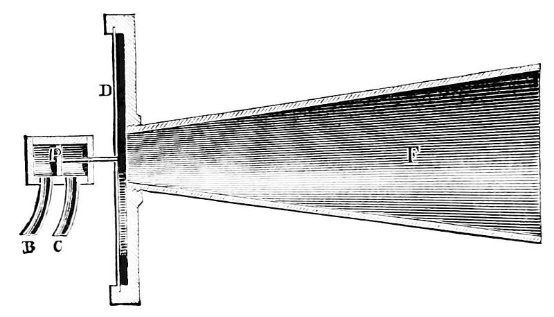
 | Left: The Gaumont Chronophone: 1910.
|
 | Left: The Gaumont Chronophone: closeup of air valve and manifold. 1910.
|
 | Left: The Gaumont Chronophone: closeup of valvebox. 1910.
|
 | Left: The Gaumont Chronophone: rear view. 1910.
|
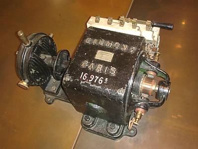 | Left: Electrically-driven air compressor for the Gaumont Chronophone
|
Gaumont was the first to suggest placing loudspeakers behind the screen, and carrying them about to follow the images on the screen! The human panpot was born.
![]()
PUBLIC ADDRESS IN GRANDVILLE
Grandville is a series of graphic novels by Bryan Talbot, depicting a steampunk world where the dominant species have animal heads and human bodies. Humans are very much second-class citizens. Inspector Lebrock is a badger, but also an inspector at Scotland Yard. On one occasion he was accused of badgering a witness. It's a brilliant series, rich in non-obvious allusions and references. If this webpage was the inspiration for Bryan's public address system, then I am a proud man.
Grandville is Paris. There's not much point in trying to assign a date, but the general feel of Grandville is Victorian.
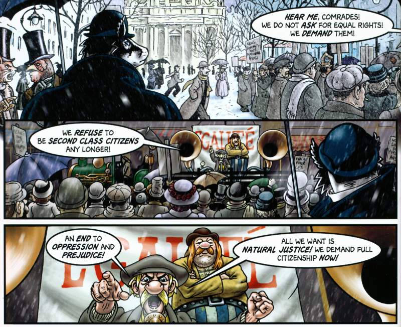 | Left: Asterix and Obelix address the crowd, while Inspector Lebrock looks on. Note the holes in his hat-brim for his ears.
|
![]()
AUXETOPHONES IN AUSTRALIA: 1909
From The Evening Star (Western Australia) p3, 22 March 1909
"CHARITY CONCERT. A decided novelty was billed for Victoria Park last night, when the auxetophone, a mammoth gramophone, was at work, the accompaniments to the songs being played on the Themodist pianola. The effect was marred by the heavy wind blowing, but sufficient was shown to display the merit of the powerful song reproducer and with the accompaniments was most lifelike. Mr. M. D'O. Musgrove played the accompaniments. At intervals the band gave some choice selections, and the concert apart from weather conditions was most enjoyable, and should result in a fine addition to the funds of the league."
But what was a Themodist pianola? The Themodist feature allowed notes to be accented or subdued, if used with a pianola roll having appropriate encoding. For straight pianolas see here.
![]()
AUXETOPHONES IN AMERICA: 1911
Here are two quotes from The Talking Machine World for September, 1911:
"Mr Grimshaw is the patentee of trumpets. tone arms, etc., which are especially adapted for this kind of work. They are suitable for gramophones and auxetophones or for any disc talking machine. His taper tone arm is a perfectly straight one, having no bends or curves."
"Victor dealers will be interested in the report that J. Ed. Beach, of Springfield, Mo, is giving auxetophone concerts in the city park there and making a success of them. He pleases large crowds with his programs."
From The Talking Machine World for July 1911; Louis F Geissler, general manager of the Victor Company speaks at a convention:
"The remarkable Auxetophone was brought out by our company after an expenditure of nearly $75,000 in patents and developments- all this before one machine was marketed. It served and is still serving its purpose, and helped us on in development and' advertisement."
![]()
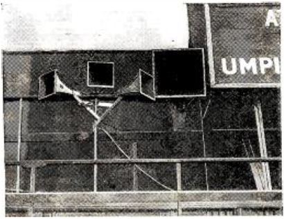
AUXETOPHONES IN CRICKET: 1921
This is from a report on the Headingley Test match in 1921.
"What made the day almost intolerable, however, was a gramophone, or rather a stentorphone, that bellowed advertisments at us during the waits. It asked us in a voice louder than was ever used for selling coal in the streets, 'Have you read the ---?' mentioning a paper of which you perhaps have never heard the name."
"At length the crowd could bear it no longer and groaned in impotent despair at each new mention of the paper. I foresee a time when all the rival papers will have stentorphones at cricket matches shouting racously against each other like bookmakers."
![]()
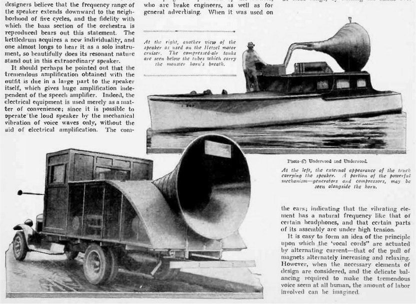
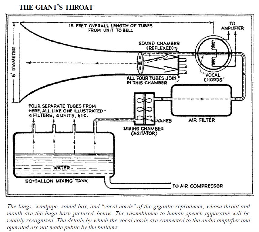
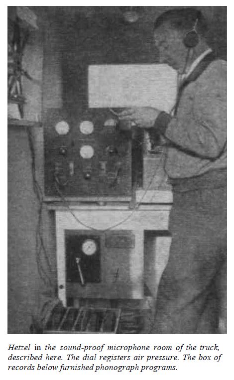
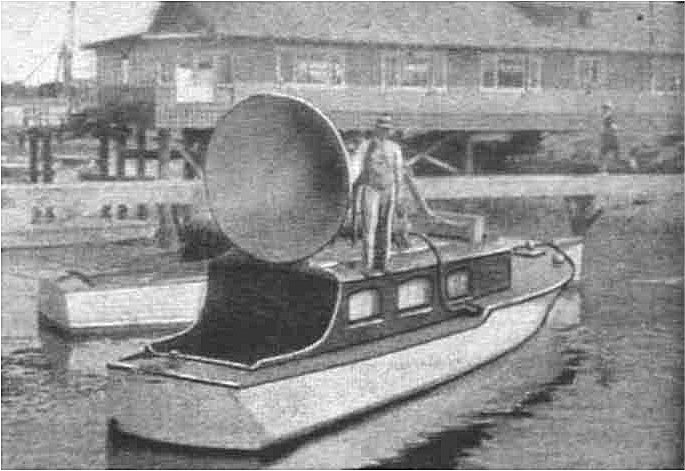
THE HETZEL COMPRESSED-AIR LOUDSPEAKER: 1929
 | Left: The Hetzel compressed-air loudspeaker: 1929
|
 | Left: The Hetzel compressed-air loudspeaker: 1929
|
 | Left: The Hetzel compressed-air loudspeaker: 1929
|
 | Left: The Hetzel compressed-air loudspeaker: 1929
|
 | Left: The Hetzel loudspeaker patent: 1933
|
![]()
THE HOOVENAIRE AIR COLUMN LOUDSPEAKER
 | Left: The Hoovenaire loudspeaker: 1931
|
 | Left: The Hoovenaire loudspeaker valve: 1931
|
 | Left: The Hoovenaire loudspeaker valve disassembled: 1931
|
 | Left: The Eaves & Dilks patent of 1935
|
 | Left: The Eaves & Dilks patent of 1935
|
 | Left: The Eaves patent of 1948
|
 | Left: The Hoovenaire air compressor: 1931
|
 | Left: The Hoovenaire inventors William C Eaves (sitting) and C F Dilks: 1931
|
![]()
RUSSIAN AUXETOPHONES
According to The Great Soviet Encyclopedia (1979):
"Pneumatic loudspeakers were used in the 1930�s and 1940�s to transmit orders and information in large harbors, river ports, and other areas with a high noise level... Such loudspeakers produced an acoustic power of up to 2 kilowatts and reproduced audio-frequency oscillations with frequencies of up to 2.5�3.5 kilohertz, with high internal noise and substantial nonlinear distortion."
Two references are given:
Olson, H. F., and F. Massa. Prikladnaia akustika. Moscow, 1938.
Beranek, L. Akusticheskie izmereniia. Moscow, 1952.
The Museum Staff have not so far been able to find copies of either of them, though the latter book seems to be quite well known.
I know little about The Great Soviet Encyclopedia. I wouldn't trust it an inch on anything political, but there seems a good chance the non-glamorous technical stuff (eg not space flight) would be accurate.
No other information on this application has been found so far.
![]()
THE FLUIDICS APPROACH: A 1960s POSTSCRIPT.
Long after the machinery depicted here came fluidics, which is fluid control without mechanical parts, and there have been a few attempts in the past to use this technology for the direct amplification of sound. See The Fluidic Gramophone which appears to have got nowhere.
Is this an idea whose time has come? I suspect not, as reading a CD with jets of compressed air presents some interesting technological challenges...
![]()
AUXETOPHONE TECHNOLOGY TODAY.
Surprisingly, it's important. Very important, in its specialised field. We probably wouldn't have got to the moon without it. Compressed air modulated by valves is used to generate enormous sound levels in test chambers.
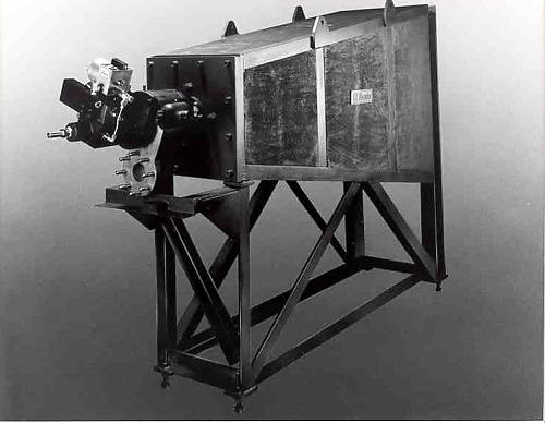 | Left: Compressed-air noise generator.
|
Sometimes it is Rocket Science.
![]()
COMPRESSED-AIR LOUDSPEAKERS AT SOUTHAMPTON UNIVERSITY
Research on these devices continues. To get up to date on air-valves and the like, see Experiments on A Compressed-air Loudspeaker (1988) by Glendinning, Nelson, and Elliott at Southampton University. (NB, PDF download) Their experiments used a sliding-plate valve driven by an electrodynamic vibrator, and levels of at least 150 dB SPL were achieved. The authors note that such loudspeakers have been available since the 1950's, and that units with acoustic power outputs from 4 kW to 20 kW are manufactured by Ling Electronics. Ling Electronics were bought out by Data Physics in 2009. It looks like they are still in the high intensity sound business.
 | Left: Cylindical compressed-air loudspeaker valve
|
 | Left: Sliding plate compressed-air loudspeaker valve
|
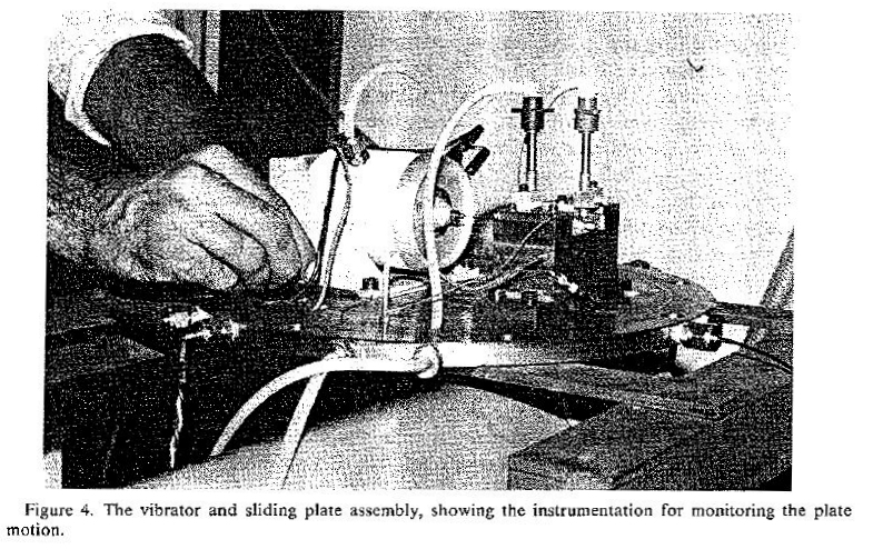 | Left: The experimantal assembly at Southampton
|
Wyle Laboratories, of El Segundo, Calif., has developed a more compact solution, the WAS 3000. It is a powerful 30,000 Watt noise source capable of producing up to 165 dB of sound.
![]()
  
|