Before the advent of the aeroplane, acoustic location was applied to determining the presence and position of ships in fog. However little faith was placed in this because the apparent direction of sounds in fog at sea was known to be sometimes deceptive.
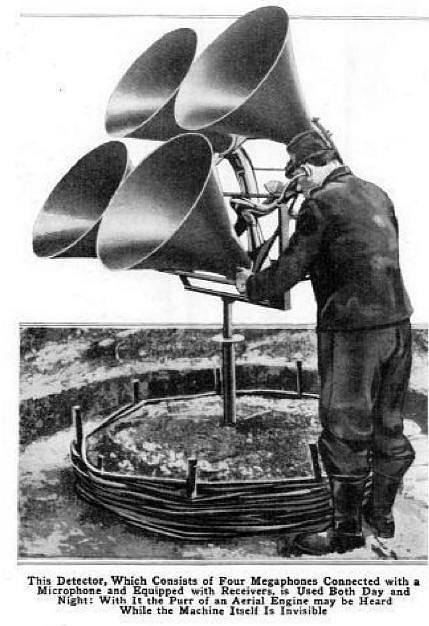
Acoustic location was used from mid-WW1 to the early years of WW2 for the passive detection of aircraft by picking up the noise of the engines. Horns give both acoustic gain and directionality; the increased inter-horn spacing compared with human ears increases the observer's ability to localise the direction of a sound. The technology was rendered obsolete before and during WW2 by the introduction of radar, which was far more effective.
Sound location was also used in WW! for locating enemy artillery, such as the Paris gun. This is not dealt with in this Gallery, but will be the subject of a future page.
There were four main kinds of system:

STEERABLE HORNS: PERSONAL
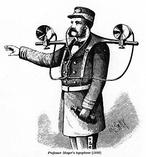 |
| Left: Professor Mayer's topophone: 1880.
This image has been reproduced many times in the past, but I could hardly leave it out, so here it is again. It was devised to assist navigation in fog. I have no information on its success or otherwise.
The Mayer Topophone was patented in the United States by Alfred M. Mayer in 1880, US patent number 224199. From 1871 until his death in 1897, Alfred Mayer was a Professor of Physics at the Stevens Institute of Technology in Hoboken, New Jersey.
I have record of two earlier devices of similar nature, that of Benjamin R. Smith (US Patent 23718 in 1859) and of James Cochrane (US Patent 110827 in 1871).
Image from Scientific American, 3rd July 1880. Patent info courtesy of Adolf Jaeger
|
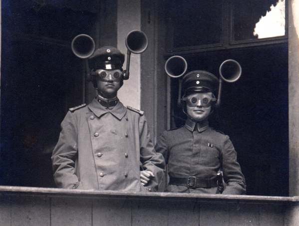 |
| Left: German sound location: 1917.
This fascinating photograph shows a junior officer and an NCO from an unidentified Feldartillerie regiment wearing combined acoustic/optical locating apparatus. This is puzzling because in Germany the anti-aircraft role was performed by the Air Service, not the artillery.
The small-aperture goggles were apparently set so that when the sound was located by turning the head, the aircraft would be visible.
Whether it was usual for officers and NCOs to stand arm-in-arm I do not know, but it seems unlikely.
Source unknown
|
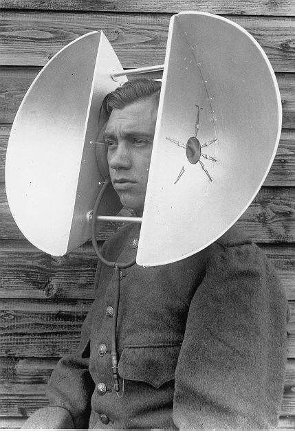 |
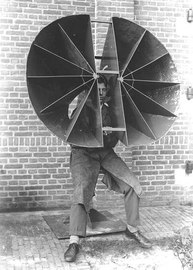
| Left: The Dutch personal parabola: 1930s
In the 1930's the Dutch set up an 'Air Watch Service', similar to the British Observer Corps, to detect incursions of foreign aircraft. It was impractical to equip the many scattered locations with the more sophisticated sort of listening devices displayed below in the 'Transportable Horns' section, so several 'personal sound locators' were developed by the Dutch military research station at Waalsdorp. Apparently this version was the most effective.
This beauty consists of two parabolic sections, presumably made from aluminium for lightness. They are mounted a fixed distance apart, but the size of the human head varies somewhat. To accommodate this, it appears that the instrument is fitted with inflatable ear-pads, to which the parabolic sections are mounted by a star-shaped arrangement of strings; tubes from each ear-pad join in a T-piece and a further tube runs down to what appears to be some sort of valve which may or may not be connected to something in our hero's top pocket. It seems likely that the ear-pads were inflated by mouth. "You can top up your air at any time..." From his pained expression, it looks as if this chap may have overdone the inflation.
According to a report dated 1935, this device was put into at least limited production.
|
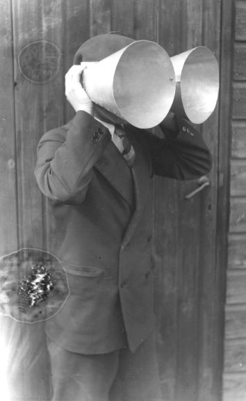 |
| Left: Dutch personal horns: 1930s
One of the experimental 'personal sound locators' tested by the Dutch military research station at Waalsdorp, before the personal parabolas above were adopted as a better solution.
|
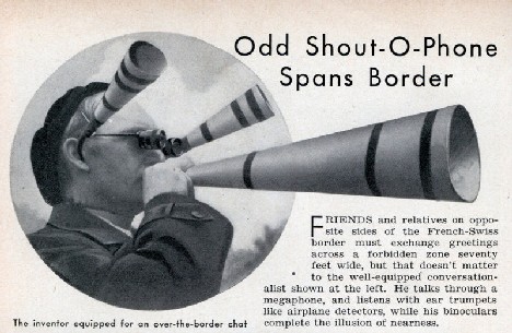 |
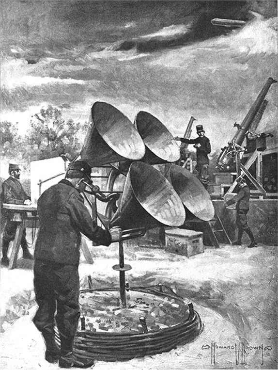
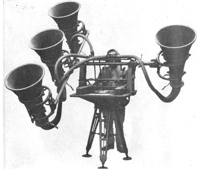
| Left: The Shoutophone: date unknown
All the information known is in the text that accompanies the picture. I believe this comes from one of the American science magazines. Probably published in the 1930s, as it is taken for granted that the readers will know what an airplane detector is.
Surely the receiving horns should be pointing directly forwards?
|
 |
|
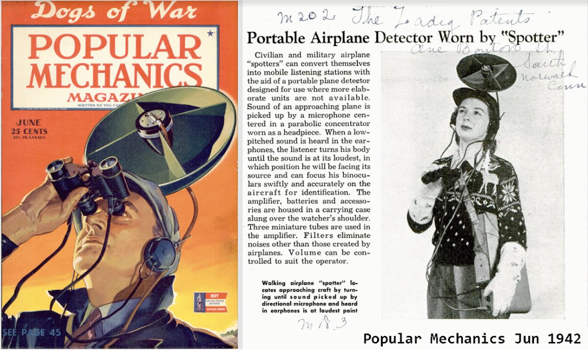
Above: Unidentified USA personal locator: 1942
The picture at right appears to show a civil defence volunteer; not, apparently, from a Scandinavian country as first thought. (the sweater) The young lady detects the aeroplane with the small parabolic reflector mounted on her head, and then identifies it with the binoculars she is holding. Such a small reflector will give little gain, but the case under her left arm presumably holds a battery-powered valve amplifier.
Very possibly this is a propaganda photo intended to draw attention away from radar, but if so it's quite convincing, apart perhaps from the inevitably small size of the dish. If anyone has any more information I would be very grateful to hear it.
The pencil annotation at the top says "The Zadig patents are..." the rest is an address "One Barton St, South Norwalk, Conn (a town in Connecticut) There is no Barton St in the Norwalk area today, possibly because half the town disappeared under a postwar interstate highway. M183 may be some sort of index number. Googling 'Zadig patent' came up with nothing.
|
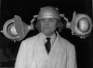 |
| Left: Jean Auscher's maritime acoustic locator: 1960.
This remarkable headgear was invented by Frenchman Jean Auscher as an acoustic navigation device in case of radar failure on small vessels. Shown at the 1960 Brussels Inventor's Fair, and, one suspects, nowhere else ever again. If he thought it was a new idea he was sadly mistaken.
This picture can also be seen in the "Failed Projects" department of the Amplifier Institute, here:
Jean Auscher.
|
TRANSPORTABLE HORNS ON STEERABLE MOUNTINGS
EARLY HISTORY
The instruments in this section are presented in chronological order. However some of the dates are a bit vague, so there has been a little guesswork in that direction.
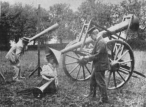 |
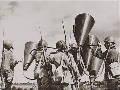
| Left: The experiments of the Rev J M Bacon: 1898.
Unfortunately, the account the Reverend Bacon gives in English Mechanic is so vague and discursive that it is impossible to work out what the purpose of these experiments was. However, it can be stated with certainty that they involved balloon ascents from Crystal Palace in London, and a small army of volunteers armed with giant ear-trumpets. It may be stretching a point to call this acoustic location, but I could not resist the picture of the Victorian lady sprawled in the grass by the cart-mounted ear-trumpet.
It is believed that the chap at left with the long white beard is the Rev John Mackenzie Bacon himself. I must admit that my first thought was that he was some sort of fruitcake, but Wikipedia put me straight; he was a Fellow of the Royal Astronomical Society, and well-respected.
From English Mechanic 30 Sept 1898, p155.
|
 |
| Left: The Rev J M Bacon takes to wireless: 1901.
Quite by accident I discovered this little nugget of history. It appears that by 1901 the Reverend J M Bacon had got with the program and was using wireless instead of shouting for balloon-ground communications.
Nevil Maskelyne was an illusionist and also a wireless experimenter. Wikipedia has a little information on him: Nevil Maskelyne.
He should not be confused with his dad, John Nevil Maskelyne, or Nevil Maskelyne, the Astronomer Royal from 1765 to 1811.
The Rev Bacon wrote a history of aeronautics called The Dominion of the Air in 1903, which is a free read at Google Books or from
archive.org.
Image from Wireless World Jan 1955, p50
|
BRITISH SOUND LOCATORS
 |
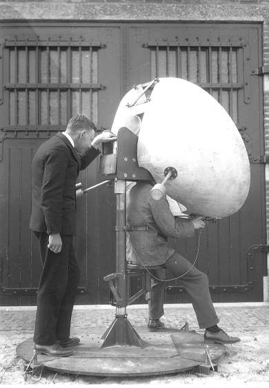
| Left: A British Mk 1 sound locator: 1914-18.
This model was used for location in the First World War, when aircraft flew relatively slowly and acoustic detection was a fairly practical proposition. It was manufactured by A.W. Gamage Ltd, who ran a famous department store in London specialising in toys, bicycles etc.
|
 |
| Left: A British Mk 1 sound locator: 1914-18.
This example is in the Canadian War Museum, Ottawa, Canada.
|
 |
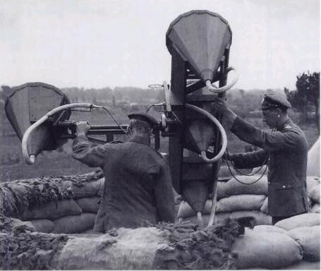
| Left: A four-horn acoustic locator
in England: 1938.
There are two horns in the horizontal plane, and two in the vertical plane. The latter are at top and bottom left of the picture. Whether the horns were of crude flat wood construction as they appear to be, or if the flat panels were a protective casing for a more conventional horn remains a matter for speculation at present.
This picture appeared in Popular Mechanics for Dec 1938. The caption describes the personnel as being from the Royal Engineers, (part of the British Army) but it seems more likely that they were actually from the Royal Observer Corps, who were civilians; however, the older chap on the right is wearing a distinctly military forage cap. Deep waters, Watson.
|
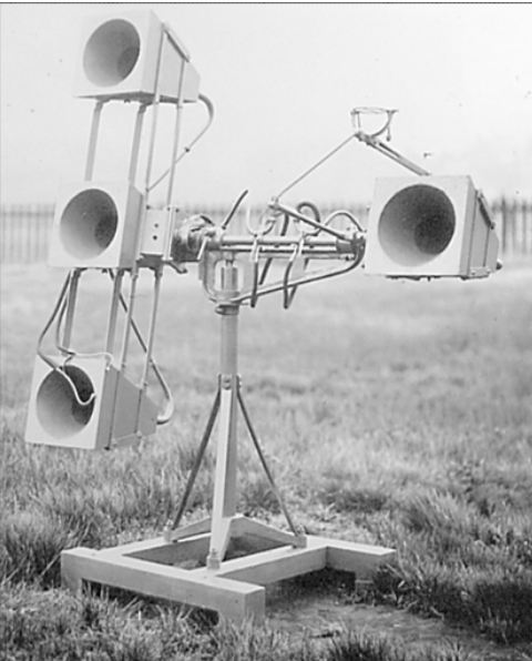 |
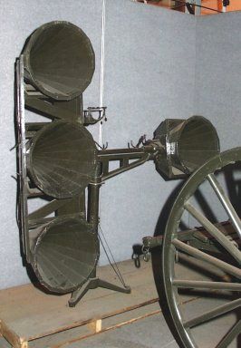
| Left: British four-horn acoustic locator: 1930s
This locator is similar to that just above, with three horns in a vertical array and the fourth out to the side. However there are differences in the details.
It is believed to have been used in tests by the Royal Engineers.
|
 |
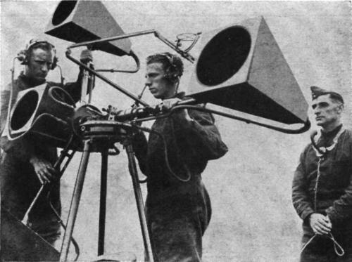
| Left: A four-horn acoustic locator again, in England: 1930s.
Once more there are three operators, two with stethoscopes linked to pairs of horns for stereo listening. The exact method of operation is currently unknown, but I suspect was as follows: the man on the left adjusts the mounting elevation until the aircraft noise is apparently central, while the chap on the right adjusts the bearing for the same result. The man in the middle reads bearing and elevation from dials and transmits it by telephone to the air defence system where the results from several locators can be combined to triangulate the target, and give its approximate height and position.
Note that this version is not the same as that above. The two horizontal-plane horns are now on the same side of the tripod.
This picture appeared in a book called Aerial Wonders of Our Time published in Dec 193?. The personnel here are definitely from the Royal Observer Corps. This was a group of civilian volunteers that had its origins in WW1. See: here. (external link)
|
 |
| Left: A contemporary cigarette card illustrating a sound locator
This is believed to date from about 1937. Other cards in the series show biplanes as fighter aircraft.
|
 |
| Left: A larger four-horn acoustic locator
Regrettably nothing has so far been unearthed about this equipment.
|
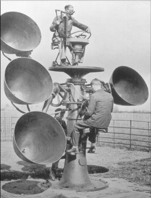 |
| Left: British four-horn acoustic locator
This locator is similar to that just above, with large parabolic horns, but the mounting is quite different.
Rather oddly, one of the operators is perched on top of the instrument. It looks as if he is controlling azimuth while his colleague half-way down the pillar controls elevation. It is unclear what the Third Man is doing.
It is said to have been used in tests by the Royal Engineers, but the three men here all appear to be in civilian dress. .
|

CZECH SOUND LOCATORS
 |
| Left: A Czech four-horn acoustic locator: 1920s?
There are two horns in the horizontal plane, and two staggered in the vertical plane. Scoop-shaped reflectors direct the sound into large-diameter tubes. Manufactured by Goerz.
When tested at the Dutch military research station at Waalsdorp it was found it "contained fundamental deficiencies".
|
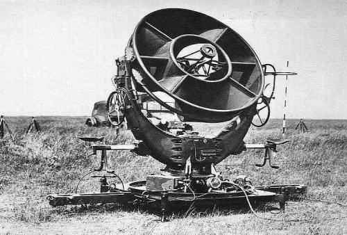
 |
| Left: The height-locating half of the Czech four-horn acoustic locator.
This picture also shows testing at Waalsdorp in Holland.
|
DUTCH SOUND LOCATORS
 |
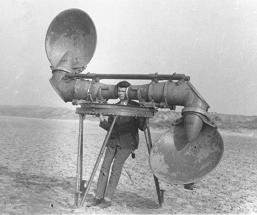
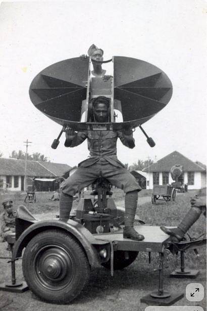
| Left: Dutch locator: 1930s
This design no doubt had more gain than the dutch personal horns, thanks to its greater area. It swivelled on the post behind the operator.
During testing at Waalsdorp in Holland.
|
 |
| Left: Dutch locator: 1930s
This is a later version of the design above. Note the extra cross-bracing added at the top of the horns. There are two counter-weights sticking out towards the rear. Rubber rings cushioned the operator's ears. This equipment was said to be accurate to two degrees.
Eighteen of these were built from 1934 onwards, for the Engineer Regiment of the Dutch Army in the East Indies. A report, dated 10 April 1934, mentions thirty more delivered, with eighty more in production.
You could argue that this device is stretching the definition of a 'personal' horn.
|
 |
| Left: Dutch locator: 1930s
This is probably another view of the device just above. How well it worked is unknown, but it certainly has the virtue of simplicity, with no hoses or pipework needed to convey the sound.
|
 |
| Left: Dutch locator: 1940
This is a Dutch locator deployed at Tijmahi (often spelled Cimahi) in Indonesia in 1940. It is manned by local troops.
Note the accompanying searchlight in the right background.
The site was used as a POW camp during the Japanese occupation.
|
 |
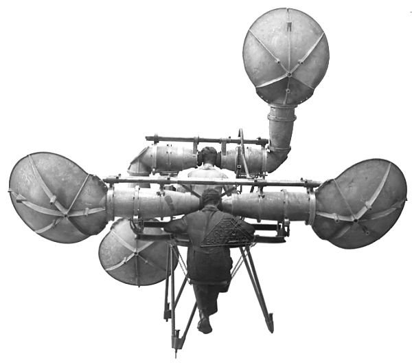
| Left: Dutch locator: 1938
This Dutch locator looks a good deal more sophisticated than the other Dutch machines, having no less than 16 horns in four groups of four. Each quartet of horns has their outputs joined together and fed into a sizable hose coming out of the back of the quartet.
The row of white dots in the right background appears to be the insulators of a telephone pole.
|
AUSTRO-HUNGARIAN SOUND LOCATORS
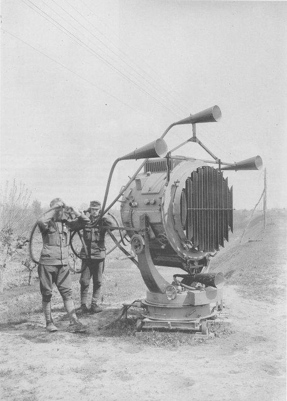 |
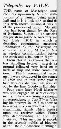
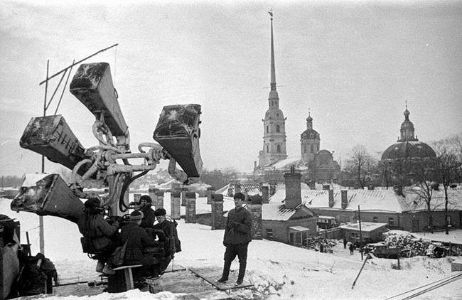
| Left: Austro-Hungarian four-horn system combined with searchlight: 1st May 1918
This image has now been identified; both soldiers are wearing puttees so that suggested the First World War. It was taken on 1st May 1918. Two Austro-Hungarian soldiers are operating the device somewhere on the Italian Front.
This does not strike me as a brilliant idea. As I understand it arc lamps are rather noisy, with lots of spitting and crackling. Not good to have right next to your locator horns. Seems like an unsound locator.
The purpose of the unusual grille on the front of the searchlight is unknown.
|
 |
| 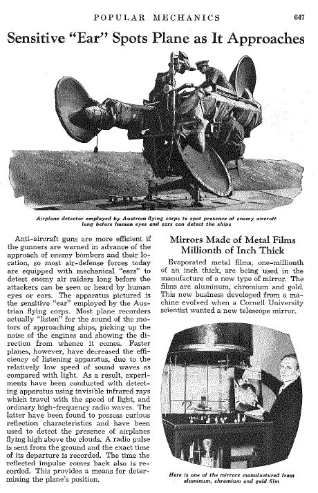 |
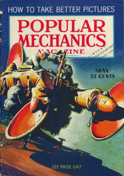
| Left: Austrian three-horn system on the cover of Popular Mechanics: 1937
The cover shows an unidentified three-horn system that bears a strong resemblance to the Czech four-horn system shown Above, except it's missing a horn. In both cases one operator puts his head right inside the apparatus.
I suspect that this is deliberate misinformation, designed to make potential enemies think that the USA was relying on sound location rather than radar. The Austrian locator looks as if it was derived from a Czech design that was already known to be ineffective. (I might point out that Austria was next-door to what was then Czechoslovakia, and before that Czechoslovakia had been part of the Austro-Hungarian empire) The accompanying article actually gives hardly any information at all, though rather surprisingly it does refer to radar and notes that it is more effective.
|
FRENCH SOUND LOCATORS
 |
| Left: French Acoustic Locator: 1916
This image appeared in Popular Mechanics for Jan 1916. It is the earliest picture of a French locator found so far.
The caption implies that electronic amplification is used, but this is highly unlikely in 1916, and there is no sign of electrical apparatus in the picture.
|
 |
| Left: French Acoustic Locator: 1915
This image appeared in Scientific American for 30 October 1915.
The caption allegedly was: "Listening for danger: electronic ears designed to listen for unfriendly airships, France, 1915." but this is clearly a later (and erroneous) addition. No electronics was involved and the term "electronics" was not used until around 1930. BUT...
This is a quote from the text of the article:
""Dr. Lee De Forest, perhaps best known as the inventor of the audion wireless detector, the audion amplifier and the audion high frequency generator, left New York for England on the mission of installing au airship detector system for the protection of London against Zeppelin raids. As far as can be learned at the present moment, the De Forest system makes use of a number of microphones placed in a geometrical figure on the ground."
Presumably he was using valves for amplification.
Note that the picture just above is exactly the same as regards the central figure, but it has been reversed left-right.
Note also the Zeppelin top right, which the listening post does not seem to have detected.
|
 |
| Left: French Parabola Baillaud: 1918
This photograph appeared in the Illustrated London News for 5th September 1936. It was claimed to show a Japanese locator, but in fact it is a "paraboloid of Baillaud" developed by René Baillaud in WW1 between 1916 and 1918, and finally adopted by the French army in 1918.
Not exactly hot news, but its publication may have been part of a deception plan to make the Germans think that the Allies were going to rely on acoustic detection in WW2. I assume the Japanese identification was just a mistake by the paper.
|
 |
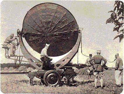
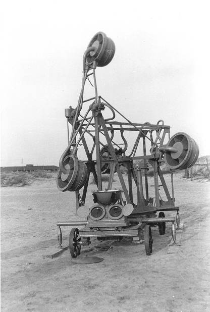
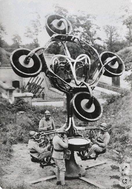
| Left: French airship detector and searchlight: 1916?
Note the six mini-horns in each of the four circular units. The function of the machine in the middle with the bicycle wheel is obscure; presumably it was to keep the locator and the searchlight pointing in the same direction.
|
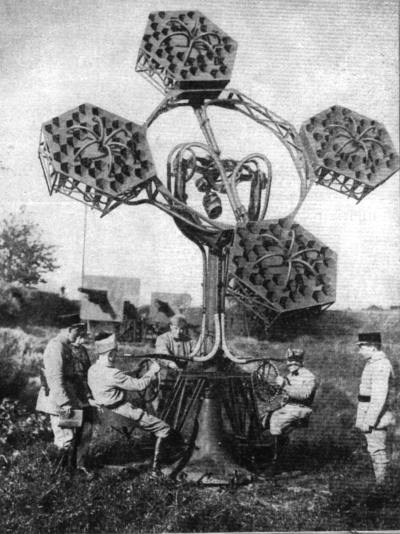 |
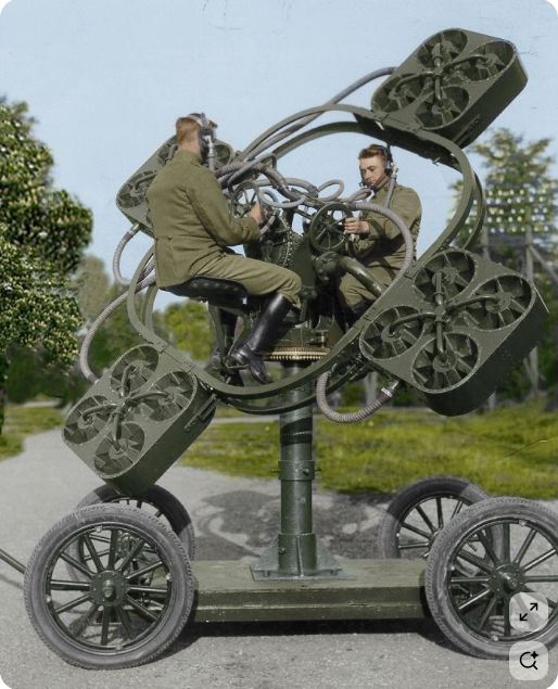
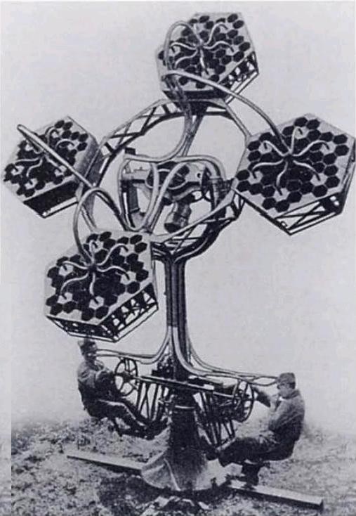
| Left: Perrin acoustic locator on trial in France: 1930s.
This remarkable machine is now identified as a télésitemčtre, designed by French Nobel prizewinner Jean-Baptiste Perrin. Perrin was an officer in the engineer corps during World War I. This machine appears to be a development of the one above; the design is now based on hexagons. Each of the four assemblies carries 36 small hexagonal horns, arranged in six groups of six. Presumably this arrangement was intended to increase the gain or directionality of the instrument.
There appear to be three operators, and two officers just watching.
|
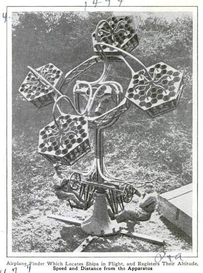 |
| Left: Perrin acoustic locator: date unknown
Further details of the Perrin locator are proving hard to come by.
Only two operators are shown here.
|
 |
| Left: Perrin acoustic locator: date unknown
Clearly a retouched version of the photograph above, with the distracting background removed.
Only two operators are shown here.
|
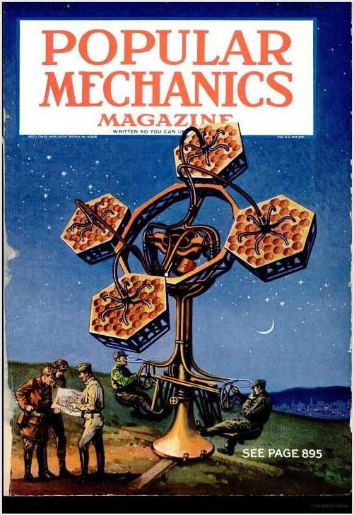 |
| Left: Perrin acoustic locator on the cover of Popular Mechanics, Dec 1930
The evolution of an image; the cover artwork is clearly copied from the retouched photograph above.
|
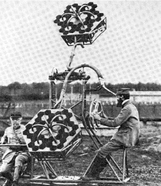 |
| Left: Perrin acoustic locator: date unknown
This version of the Perrin locator has only two horns. It is not clear what the depressed-looking fellow on the left is doing, but his colleague on the right appears to be in charge of adjusting both bearing and azimuth, using two coaxial hand-wheels.
This picture is believed to show operation during WW1, but this is unconfirmed.
|
 |
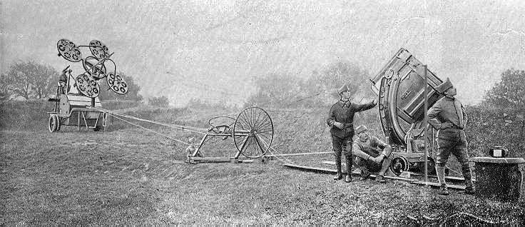
| Left: French locator by Barbier, Bénard and Turenne
It is shown here being evaluated at the Waalsdorp research station in Holland in the 1930s, for possible use by the Dutch army. There are four horns, one of them being at the rear.
The French firm of Barbier, Bénard and Turenne (French Wikipedia) was founded in 1862. It specialised in the manufacture of lights, optical devices and lighting systems. The firm was dissolved in 1982.
At the front of the trolley are two round things with hinged covers; I would be intrigued to know what they were. There is an equally mysterious sort of kettle-drum just above them.
|
 |
| Left: French locator: date unknown
The sound-collecting horns look very much like those in the Barbier, Bénard and Turenne locator image just above, but the pipework is of larger diameter. The transport platform is quite different.
It looks as if the operator sat in the middle of the upper cradle, with two big pipes bringing the sound to his ears. The wheel in front of him presumably traversed the equipment.
|
 |
| Left: French locator: date unknown
Once again the horns look very much like those in the Barbier, Bénard and Turenne locator above.
Two operators are listening and gripping handwheels while the man at the front uses a telephone; he appears to be studying a round plotting table.
The four men are wearing the distinctive Adrian helmet with a ridge on top.
|
GERMAN SOUND LOCATORS
 |
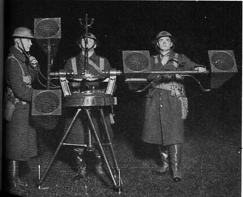
| Left: Commercial German acoustic locator in use
This device was based on the researches of Erich von Hornbostel. With Max Wertheimer, he developed in 1915 a directional listening device that they referred to as the Wertbostel. This device seems to have had some success as they were still discussing licence fees with manufacturers as late as 1934.
|
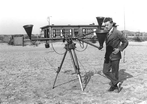 |
| Left: Commercial German acoustic locator on trial
The locator looks like a three-horn design here but in fact the fourth-horn can just be seen behind the operator's head. This was a commercial version of the Wertbostel described above, manufactured by Askania of Germany. It is shown here being evaluated at the Waalsdorp research station in Holland in the 1930s, for possible use by the Dutch army. It was obsolete and found to be unsatisfactory, very likely because the small horns would have given little acoustic gain.
It was formally called a "Doppelt Richtungshörer" or "Double-direction listener" but informally, a Wertbostel, a combination of the inventor's names.
|
Askania Werke (German Wikipedia) also manufactured sound locators and blind-flying instruments under licence from Sperry Gyroscaope in the 1930's. At this time there was free exchange of information between the USA and Germany.
 |
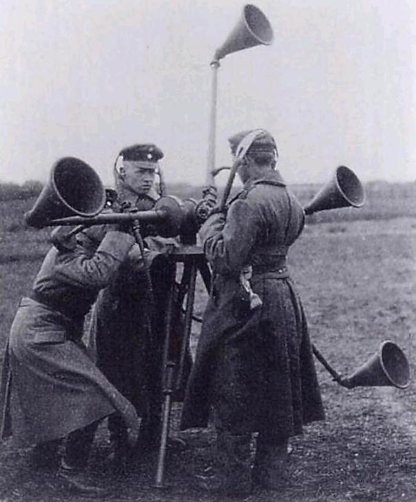
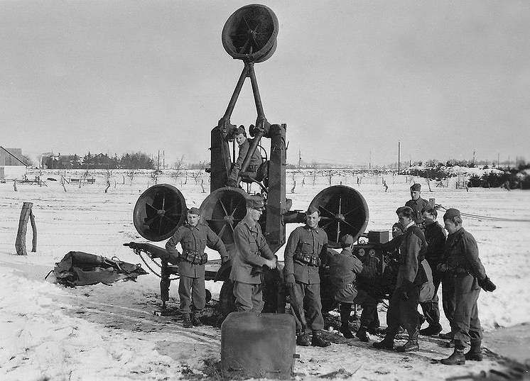
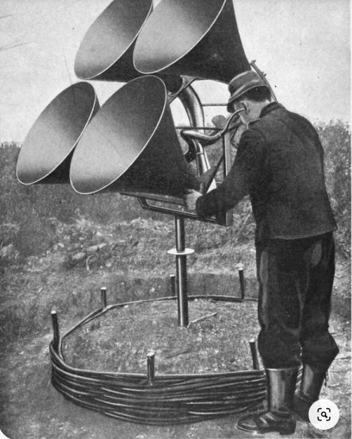
| Left: A German RRH acoustic locator at an unknown location: 1940s?
This much more impressive piece of apparatus was called the Ringtrichterrichtungshoerer (or RRH) which Matthias Warkus tells me translates literally as "ring funnel direction hearer", or more accurately: "ring-horn acoustic direction detector".
The RRH was mainly used in World War 2 antiaircraft searchlight batteries for initial aiming of the searchlights at night targets, presumably because it was cheaper and easier to make than a radar set. Later in the war they were replaced by radar sets.
Like the British and French versions, the RRH was also composed of four horns, two to determine bearing, and two for elevation, arranged in aring. The two lateral horns have a horizontal bar across their mouths.
Picture by kind permission of Helge Fykse.
|
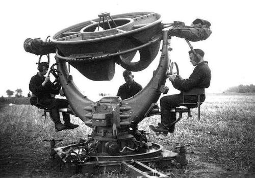 |
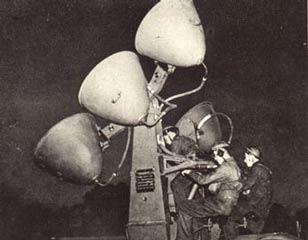
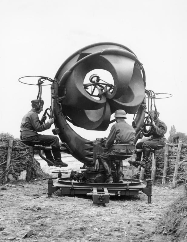
| Left: The RRH acoustic locator with operators at their posts.
The RRH could detect targets at distances from 5 to 12 km, depending on weather conditions, operator skill, and the size of the target formation. It gave a directional accuracy of about 2 degrees.
It had a crew of three - traverse aimer on the left seat, elevation aimer on the right seat and a dial-reader/talker in the middle. The rolled-up material above the operators' heads could be unfurled to provide shelter.
The curved things visible under the ring are the rear of the horns.
Picture by kind permission of Helge Fykse.
|
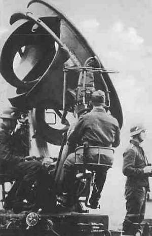 |
| Left: The German RRH acoustic locator
This gives a better view of the rear of the horns, curved for compactness.
|
 |
| Left: The German RRH acoustic locator: 1939
This photograph was allegedly taken in or near Berlin in 1939, and published in a propaganda article. It was described thus:
"Flak protects Berlin"
"A broad iron defensive wall stretches in a wide arc around the Reich capital, a secure haven against enemy air attacks. Day and night, the men of the air defense are on guard, whether at the anti-aircraft gun, the searchlight, the listening device, or as crew members of our fast fighters. We present photographs from our photojournalist's visit to the anti-aircraft artillery."
"Caption: one of the enormous listening devices that can pick up even the faintest engine noise."
|
Note that the background has been retouched out. The setting looks rural, rather than in Berlin.
Thanks to Bernd F for drawing this image to my attention
Photo source: Iron. Oct. 1939
|
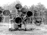 |
| Left: German acoustic locator for heavy flak units
Regrettably a poor quality image, but showing a completely different design with a conventional four-horn format.
|
JAPANESE SOUND LOCATORS
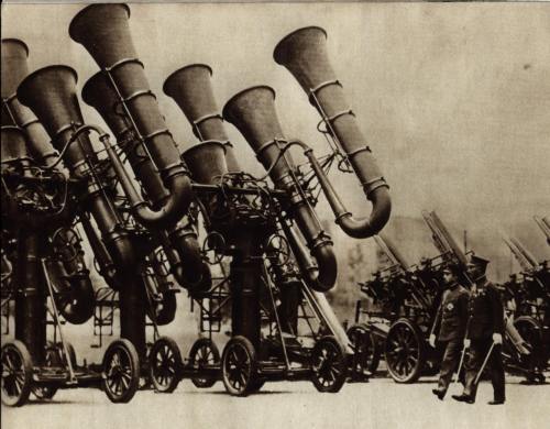 |
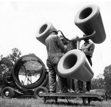
| Left: Acoustic locators in Japan: 1936
This remarkable picture may have been reproduced before, but I make no apology for showing it here. The impressive array of Japanese war-tubas belong to at least two acoustic locators mounted on 4-wheel carriages. It is a little difficult to work exactly what is connected to what, not least because the background appears to have been erased by some unsubtle retouching, but I think that the format is the same as the British model; there are two horns in a horizontal plane, and on one side of the mounting there are two more in a vertical plane. The equipment was called the 'Type 90 Large Detector'. There was a smaller version called the 'Type 90 Small Detector'. See below.
To the right, one of the figures is the Japanese emperor Hirohito. Behind him are the AA guns intended to be used in conjunction with the locators. The only Japanese gun that I have found documented as being used with a sound locator is the Type 88 dual-purpose AA/coast-defence 75mm; there is not enough visible detail to verify that these are the guns shown in the picture, but they look about the right size.
This picture was the subject of a Fark Photoshop competition: see here (external link)
|
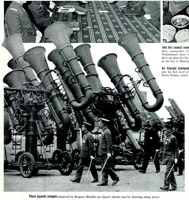 |
| Left: The Japanese war-tubas again: 1936
This picture, of rather better quality, was clearly taken just after the one above. I am fairly sure that Hirohito is the man on the left.
Note that they are describes as electric ears, which implies that valve amplification was used.
From the US magazine Life, 28 Dec 1936
|
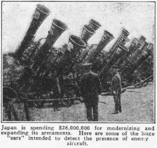 |
| Left: Acoustic locators in Japan: 1936
Nothing much is known about this picture of less than stunning quality, but it appears to show the same war-tubas as the picture above. Note the Japanese characters on the side of trumpets.
From the US magazine Mechanics & Handicraft, Jan 1936
|
 |
| Left: The Japanese Type 90 Small Detector: 1930s
Clearly a very similar design to that of the Japanese Type 90 Large Detector, shown above.
|
 |
| Left: The Japanese Type 90 Small Detector: 1930s
Can anyone translate the markings on the horns?
|
RUSSIAN SOUND LOCATORS
 |
| Left: A Russian 4-horn locator
No further info currently available.
|
SWEDISH SOUND LOCATORS
 |
| Left: A Swedish 4-horn locator in 1940
No further info currently available.
|
USA SOUND LOCATORS
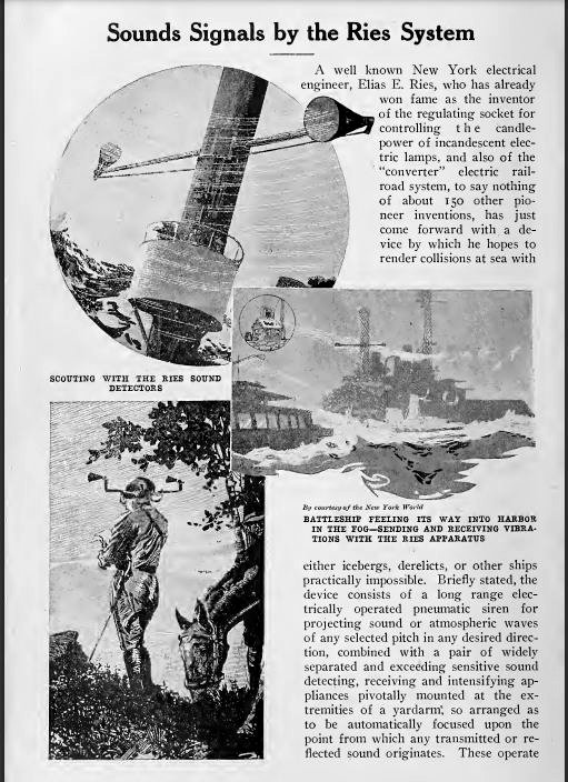 |
| Left: System proposed by Elias Ries, USA: 1912
The top picture is rather puzzling as the two conical horns are pointing in wholly different directions. The man in the crows-nest presumably rotated the horn-bearing arm around the mast.
The picture at bottom left shows a horseman using a personal locator that is notable because its horns are ridiculously small- apparently smaller than the man's actual ears. Note that he wears a sword on his left hip; this is 1912, and swords in warfare are no longer relevant.
Note also the refence to icebergs. The RMS Titanic (operated by the White Star Line) sank in the North Atlantic Ocean on 15 April 1912 after hitting an iceberg. This very likely inspired Mr Reis.
Source Popular Electricity magazine 1912, p758. Thanks to Paul Reid for bringing this to my attention
|
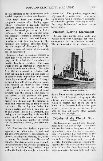 |
| Left: System proposed by Elias Ries, USA: 1912
This is the second page of the article. It claims that the personal locator can have "any desired range" which is obviously nonsense. 'Three to five miles' also sounds wholly impracticable.
Source Popular Electricity magazine 1912, p758.
Some biographical info on Mr Reis:
|
|
RIES, ELIAS ELKAN:
By: Cyrus Adler, Frederick T. Haneman
"American electrical engineer; born at Randegg, Baden, Germany, Jan. 16, 1862. When only three years of age he was taken by his parents to America. He received his education at the public schools of Baltimore and New York, attending also lectures at Johns Hopkins University, Baltimore. In 1876 he became a telegraph-operator and removed to New York, being employed by the Edison Company and other electrical concerns. Returning to Baltimore in 1884, he developed some of his own inventions in electrical signaling, and organized (1891) the Ries Electric Specialty Company. Since 1896 he has resided in New York city."
"Ries has invented improvements in the telephone, the telegraph, and in other electric apparatus, such as electric lamps, track-rail welding machinery, motor controllers, etc., for which inventions he has secured about 150 patents. He has also contributed articles to the scientific and technical journals."
|
|
Source: American Jewish Year Book, 1905, s.v.
See also here.
Mr Reis died of pneumonia in April 1928.
|
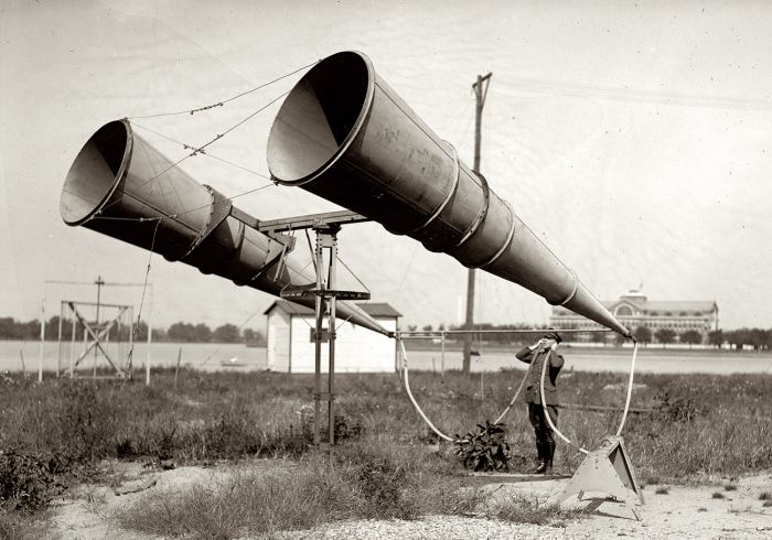 |
| Left: A two-horn system at Bolling Field, USA: 1921
The type number for this locator is currently unknown. Note conical, not exponential, horns.
The building in the background is the Army War College at Fort McNair.
|
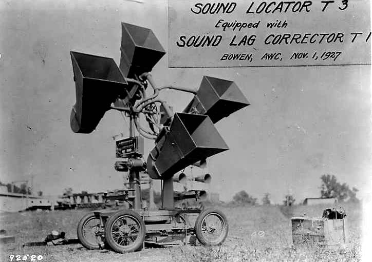 |
| Left: A T3 four-horn system in 1927
This is a T3 aircraft sound locator used by the U.S. Army Signal Corps. The horizontal pair of square horns determined the azimuth of the aircraft, and the vertical pair determined the elevation. The word "BOWEN" on the label is believed to refer to Admiral Harold Gardiner Bowen (1883-1965) who was then directing air defense research at the Naval Research Laboratory and was later involved in developing radar. "AWC" probably indicates that the photograph was taken at the US Army War College, Fort McNair. This is believed to be an official US Army Signal Corps photo.
For a long time the "Sound Lag Corrector T1" was deeply mysterious and unknown to Google. Now, however you can read all about it in the Coast Artillery Field Manual 4-111, issued in 1940. The production of this comprehensive manual in 1940 seems to indicate that the USA were still putting some faith in sound location at that date. Enjoy!
The sound lag corrector was employed because sound travels very slowly compared with speed-of-light radar pulses, so the target may have moved on significantly by the time its sound reaches the locator. Corrections were also made for wind error, and parallax caused by the locator and the spotlight it was guiding not being at the same point.
There seems to be another locator with four round horns just visible at the lower right of the locator in the foreground.
|
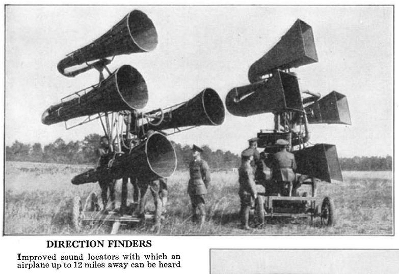 |
| Left: Two USA sound locators: 1929
The locator with the square horns on the right is clearly the same type as the one in the picture just above. Note the wheels here still have spokes.
The locator on the left, showing segmented circular horns with external bracing, has not been encountered before.
Source: Article in Scientific American May 1929. It was written by Major G M Barnes of the US Army Ordnance department, so I think we can take it as authoritative.
|
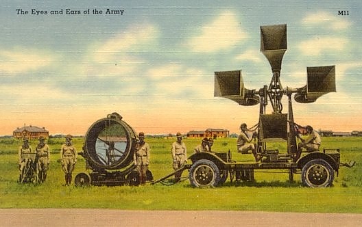 |
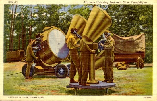
| Left: A T3 sound locator with its associated 60-inch searchlight
Note the more modern wheels than in the photo above.
Contemporary postcard, date unknown, but probably early 1930's.
|
 |
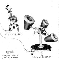
| Left: An M2 sound locator with its associated 60-inch searchlight: 1940
The M2 locator was a later development; it was in use around 1940.
There are three horns and not four, the horn at top right being shared between the horizontal and vertical planes, by splitting its output tube.
From the Coast Artillery Field Manual 4-111:
"The spacing of the horns varies in the different designs. Theoretically, the accuracy of the instrument increases with
the length of the base line. The older models have a base line length of 112 inches. Recent exhaustive tests have shown
that there is not much gained in accuracy if the length of the base line exceeds 60 inches. The new models have the
shorter base line, thereby decreasing the weight and size of the instrument."
And if you're wondering why the shape of the horns has altered so radically:
"Recent extensive tests in the laboratory and in the field have indicated that horn size and horn shape have little influence on the range of the sound locator. Hence, the latest models do not have the exponential horn but a horn which has certain other characteristics."
"Ambient noises are reduced greatly by the design of the latest type of sound locator. This type features sound
insulating and vibration dampening materials, streamlining of the horns and supporting structure, and making the horn
definitely directional within a 30° cone in the direction of the axis of the horn."
|
|
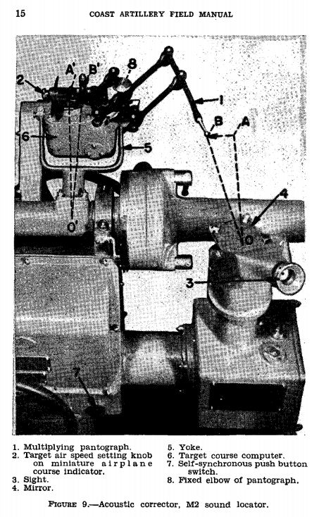 |
| Left: Acoustic corrector and sighting arrangements on the M2 locator
The system made corrections in both altitude and azimuth. There was a three-man team; one man guided the sytem in altitude, one in azimuth, while the third man added the acoustic corrections.
The corrections involved some complicated calculations, which were performed by a mechanical analogue computer, apparently housed in the small box labelled 6, though it hardly looks large enough. The basis of this computer was a ball resolver, also known as a spherical resolver. This computing device has no Wikipedia page, and I have failed to find a good link.
So far as is currently known, no other country added acoustic correction to its locators.
|
Another official document referring to the M2's immunity from external noise:
"These requirements are met by the sound locator M2 in the following manner:
a: Reverberation of the horn structure is reduced to a minimum by constructing the horn of an impregnated cloth composition and covering all metal parts in the sound system with vibration damping material.
b: Wind effect is reduced to a minimum by eliminating all sharp corners and streamlining the horn contours.
c: The sound conducting tubes are insulated from the supporting structure and from the outside horn case, which reduces the transmission of noise from gears, bearings, wind, rain, hail, etc.
d: The horn is of the semi-exponential type, with the dimensions chosen to provide a "directional" characteristic.
e: The effect of ambient noise may be reduced by proper placement of the sound locator with respect to surrounding objects. It should be positioned at a point distant from the searchlight, the searchlight power plant, highways, trees, and other objects constituting either
an actual or possible noise source. In addition, it is essential that personnel operate with the absolute minimum of noise. Sound discipline must be enforced in the vicinity of the sound locator for best results."
This explains why the horns on the M2 look so different from most other locators. The front is rounded off to minimise wind noise, and the rounded outer body reduces the effect of extraneous sound on the inner horn.
 |
| Left: Inside an M2 locator horn
This shows the extensive efforts made to meet the problems listed above, using latex foam and flameproof felt for vibration insulation.
I'm starting wonder just why the USA put so much development effort into the M2 locator. Were they pessimistic about the possibilities of radar?
|
 |
| Left: The gearing of an M2 sound locator
This shows the considerable complexity of the M2 locator. The gearing by which the azimuth and elevation corrections were applied is at the bottom right.
The horns are coloured green.
The ball resolver, mentioned above, is at upper centre. (pale blue)
In the middle of the picture are the two tranmitters which sent azimuth and elevation to the searchlight. (orange)
|
 |
| Left: A US Army M2 sound locator for a mobile searchlight unit: early 1940s
The locator and searchlight control station were connected by cables to the searchlight and a mobile electric generator.
These locators continued to be deployed when radar sets were introduced, in the hope of convincing the Germans that the US searchlight battalions were still dependant on acoustic location.
|
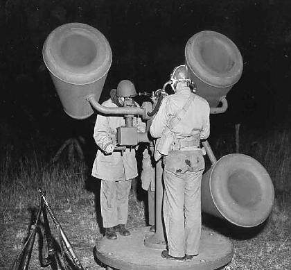 |
| Left: A US Army M2 sound locator in use: 1943
This photograph was dated January 1943, and was presented by the American media as being current equipment. This was probably another piece of misinformation as radar sets were already in widespread use for searchlight control at that date. The M2 sound locator was however the standard for most searchlight units at the start of World War 2. The unit could be broken down into six components for ease of transport. It incorporated newer materials and an updated design to reduce interference from ambient sounds, whether environmental or from noise induced by its own mechanisms.
The three operators stood on a platform that was acoustically decoupled from the ground and also enabled leveling of the locator. The perceived azimuth and elevation of the distant sounds were tracked by handwheels. Built-in mechanisms compensated for sound lag errors caused by the relatively slow speed of sound. Correcting mechanisms were also provided for errors caused by wind and the placement of the locator relative to the searchlight.
Note the large diameter acoustic tubes leading to the operator's headset. The cross-section of the tubing decreased exponentially from the
elbow assembly at the horn to the listener's ears, with the exception of the short external sections called helmet tubes, extending from
the mounting to the listener's ears. This exponential decrease formed an extension of the horn throat and intensified the sound.
|
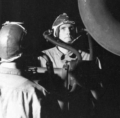 |
| Left: The two listening members of an M2 sound locator crew
The M2 was provided with special acoustic helmets designed to exclude extraneous sounds.
The effective range of the M2 sound locator was considered to be between 2,000 and 8,000 yards. Range was very dependent on atmospheric conditions and the skill of the operators, and could vary widely from day to day. With the introduction of the SCR-268 radar for searchlight control, the M2 sound locator became obsolete and was rapidly replaced, but some searchlight organizations retained the M2 throughout the war and occasionally used them to supplement local radar.
|
 |
| Left: The special M2 acoustic helmets
The M2 helmets were constructed of soft pliable leather, lined with chamois. They were provided in the two sizes, medium and large, and fitted with four lacings (front, rear, crown, and chin) so a good fit could be obtained.
Aluminum elbows attached to the ends of the helmet tubes, were a "snap fit" into the helmet bushings. This provided a quick method of attachment
and eliminated the need to removing the helmet during non-active periods.
|
 |
| Left: An M2 sound locator with its associated 60-inch searchlight
Contemporary postcard, date unknown.
|
CHINESE SOUND LOCATOR POSTERS
These posters were issued in the early 1930s. In 1931 Japan had seized Manchuria from the Chinese, and there were also confrontations with the Russians. It was not a peaceful area.
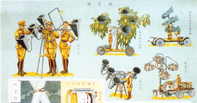 |
| Left: Chinese poster: early 1930s
This seems to be some sort of recognition aid for foreign sound locators.
The picture on the left is of the British 4-horn locator.
The picture upper middle with the luxuriant vegetation looks very like the 'sound locator of unknown origin' shown just below.
Lower middle looks like the Japanese "war tuba" 4-horn locator.
Upper right is the American T3 locator.
Lower right is the French locator.
|
You may be wondering why the Chinese were concerning themselves with locators whose home countries were so very far away. I strongly suspect this is due to memories of being thoroughly defeated by the Eight Nation Alliance which was formed to protect foreign nationals during the Boxer Rebellion. The Alliance consisted of Austria-Hungary, the British Empire (including Australia and India), Germany, France, Italy, Japan, Russia, and the United States. Four of these countries are represented in the poster.
SOUND LOCATORS OF UNKNOWN ORIGIN
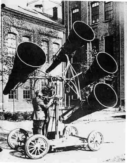 |
| Left: An early four-horn system, date and nationality unknown
Unfortunately I have no information at all about this photograph. The uniform suggests the First World War to me, as the operator appears to be wearing high boots, but this is far from certain.
Some years on, this device remains tantalisingly unidentified. You will note that it (or something extremely similiar) appears swathed in greenery on the Chinese poster just above. In fact, I think that the Chinese drawing was done from this photograph. The position of the operator is identical, and the carriage appears the same, even having the correct number of spokes on the wheels. This suggests that its nationality is one of the countries in the Eight Nation Alliance, and my slowly hardening suspicion is that it's an early American model.
|
 |
| Left: Four-horn system, date and nationality unknown
Judging by the man's cap, this is probably a French locator.
|
 |
| Left: Four-horn system, date, nationality, and location unknown
One of the horns has been detached from its mounting.
|
 |
| Left: Four-horn system, date, nationality, and location unknown
This locator does not match exactly with any of the others on this page. At any rate it is in an army where bayonets were fixed at all times. That could be Japan or Russia. Perhaps someone can identify the helmets?
|
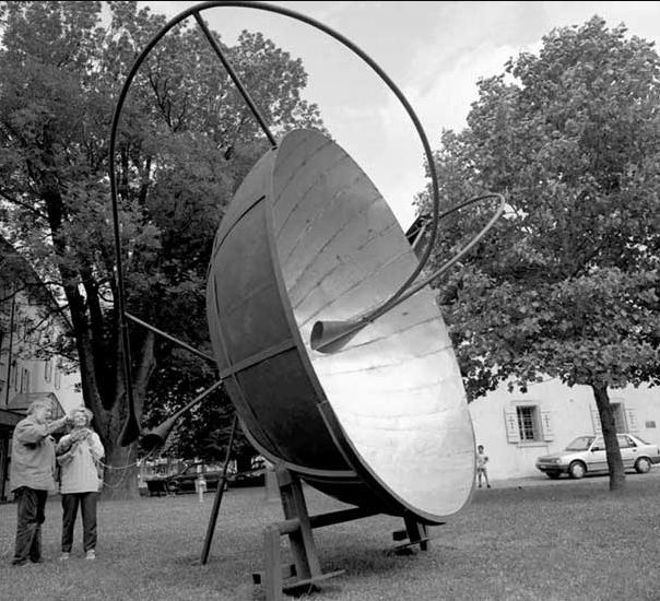 |
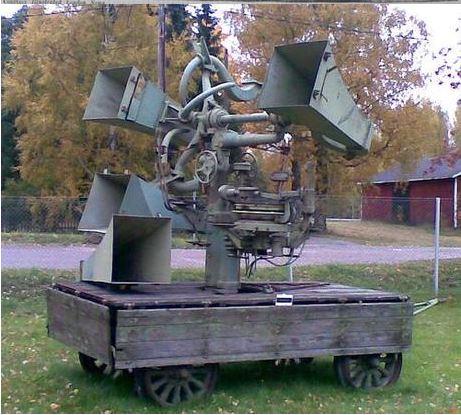
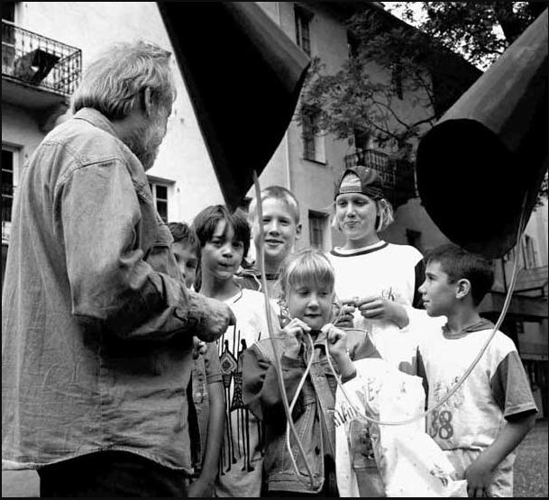
| Left: A parabolic horn as working sculpture; date, nationality, and location unknown
This big parabola with two horns near the focus is of modern construction. It is not intended to detect aircraft.
A reverse image search yields nothing.
|
 |
| Left: Four-horn system, date, nationality, and location unknown
The listening end. It looks as though you can listen either via the black horns or ear tubes.
|
STATIC DISHES
Steerable horns are inevitably limited in size, even in Japan, but a static dish can be much larger, giving more acoustic gain and the possibility of detecting aircraft at greater ranges. The first static dish was cut into a chalk cliff face between Sittingbourne and Maidstone in July 1915. Interestingly, the mirror was shaped to form part of a sphere, not part of a parabola, the latter always being used for radio aerials, searchlight reflectors, telescope mirrors etc. The part-spherical shape presumably gives better off-axis performance at the expense of on-axis precision, and it appears that all later static dishes and walls used a spherical/circular shape.
The 1915 dish had a sound collector on a rotating mount at the "focal point".
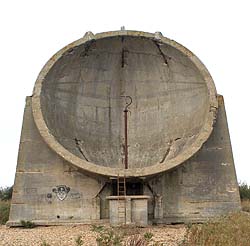 |
| Left: An acoustic locator dish in Kent, England: built 1928.
This 30-foot high dish is located at Greatstone, Kent. The small concrete hut in front housed the operators. The vertical mast in the centre carried the acoustic pickup tubes.
A static dish can be much larger than a fully steerable horn, giving more acoustic gain and the possibility of detecting aircraft at greater ranges. The pickup tube could be moved sideways to "steer" the direction of maximum sensitivity by a limited amount.
|
STATIC WALLS
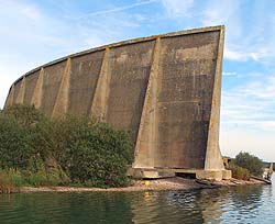 |
| Left: An acoustic locator wall at Greatstone, Kent: built 1930.
A mirror has to be much larger than the wavelength of what it is reflecting to work efficiently. This 200-foot wall was a later development designed to concentrate audio wavelengths in the 15 to 18 foot range, which were not handled effectively by 20-foot and 30-foot dishes.
The wall could detect aircraft at 20 to 30 miles distance. This may not seem impressive, but in aircraft interception every second is valuable. With its later microphone installation the wall had a bearing accuracy of 1.5 degrees.
|
By 1935 it was clear that radar was going to be a much more effective way of detecting aircraft, and all work on the sound mirrors was stopped, and the funding diverted to radar research.
However, interest in the sound mirrors was briefly revived in 1943 when it was feared that Germany might have developed an effective method of jamming the British coastal defence radar stations. Post Office engineers made tests at the Greatstone mirror to see if the mirrors could be used after all in case of emergency. Improved electronic equipment in the detectors meant that it was now possible to detect enemy aircraft as far as 50 miles out. In the event the radar stations were never effectively jammed and the mirrors were never needed.
Britain never publicly admitted it was using radar until well into the war, and instead publicity was given to acoustic location, as in the USA. It has been suggested that the Germans remained wary of the possibility of acoustic location, and this is why the engines of their heavy bombers were run unsynchronised, instead of synchronised (as was the usual practice, to reduce vibration) in the hope that this would make detection more difficult.
HISTORICAL NOTES
The first Japanese attack on the fortress island of Corregidor (in the Phillipines) on 29th December 1941 was detected by American acoustic locators.
LINKS
There is a good bit of information on the Web about this technology, if you use the right search words. "Sound mirrors" works better than "Acoustic locators".
Acoustic detection and location is not a dead technology. See:
The acoustic detection of aircraft over snow
You will be glad to know that this page was rated "cool" by Fark.
Here are the Fark comments on the page: Fark comment


