Page opened: 31 Jan 2011
Updated: 18 Jan 2024
Added:
Rumble filters added
More on Tobey & Dinsdale amplifier


The Wireless World Archive |
Page opened: 31 Jan 2011 |
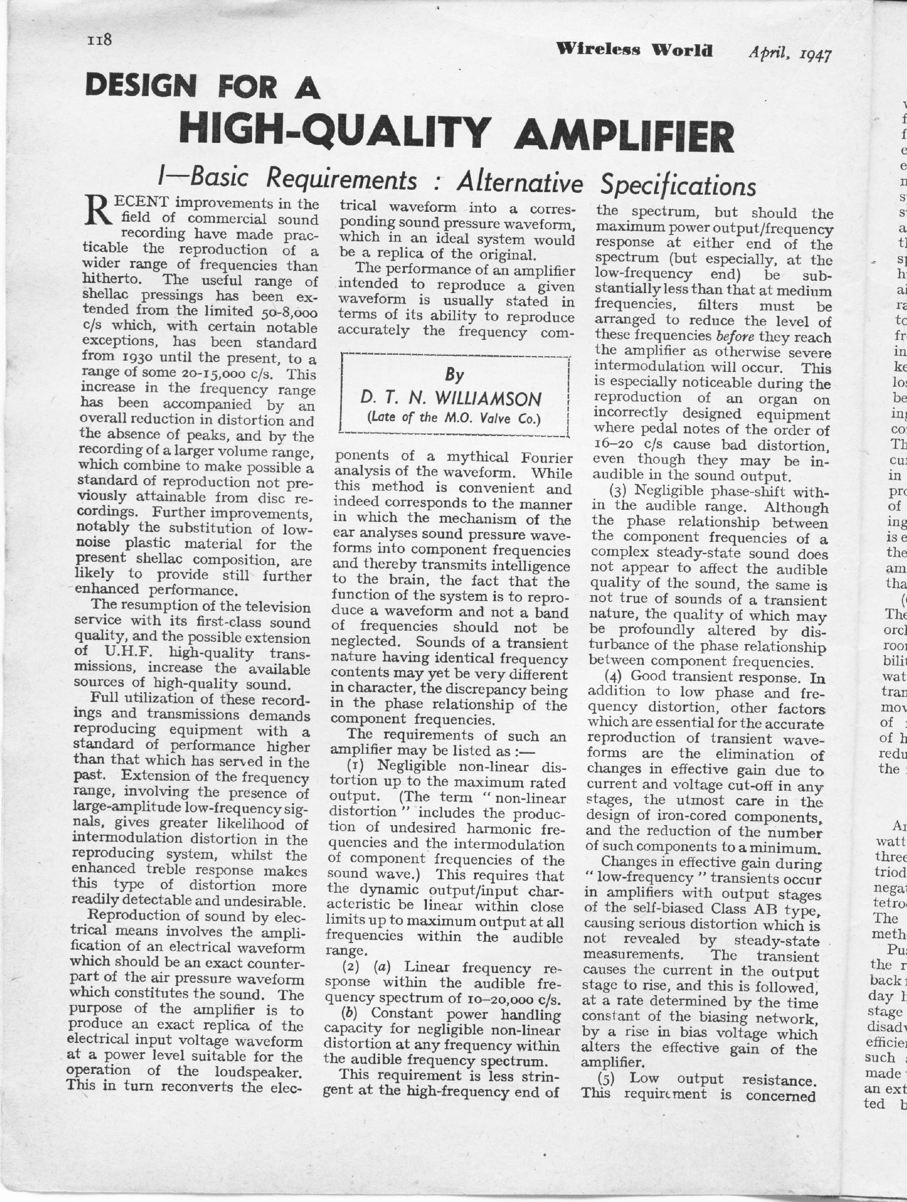
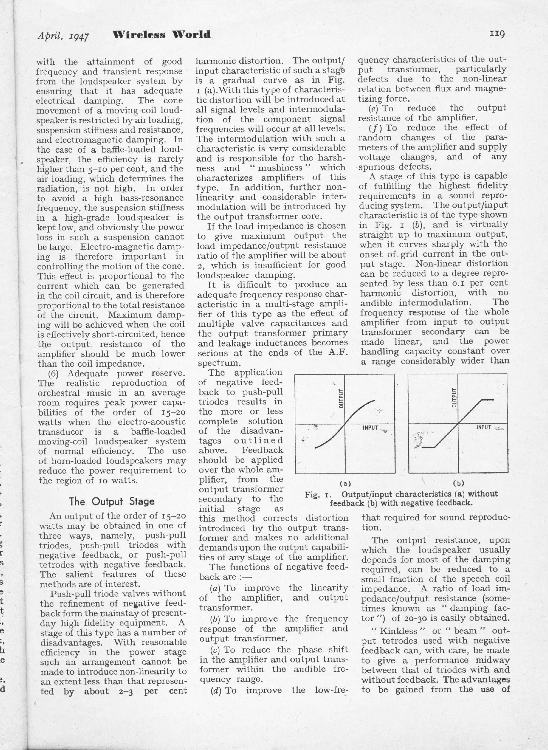
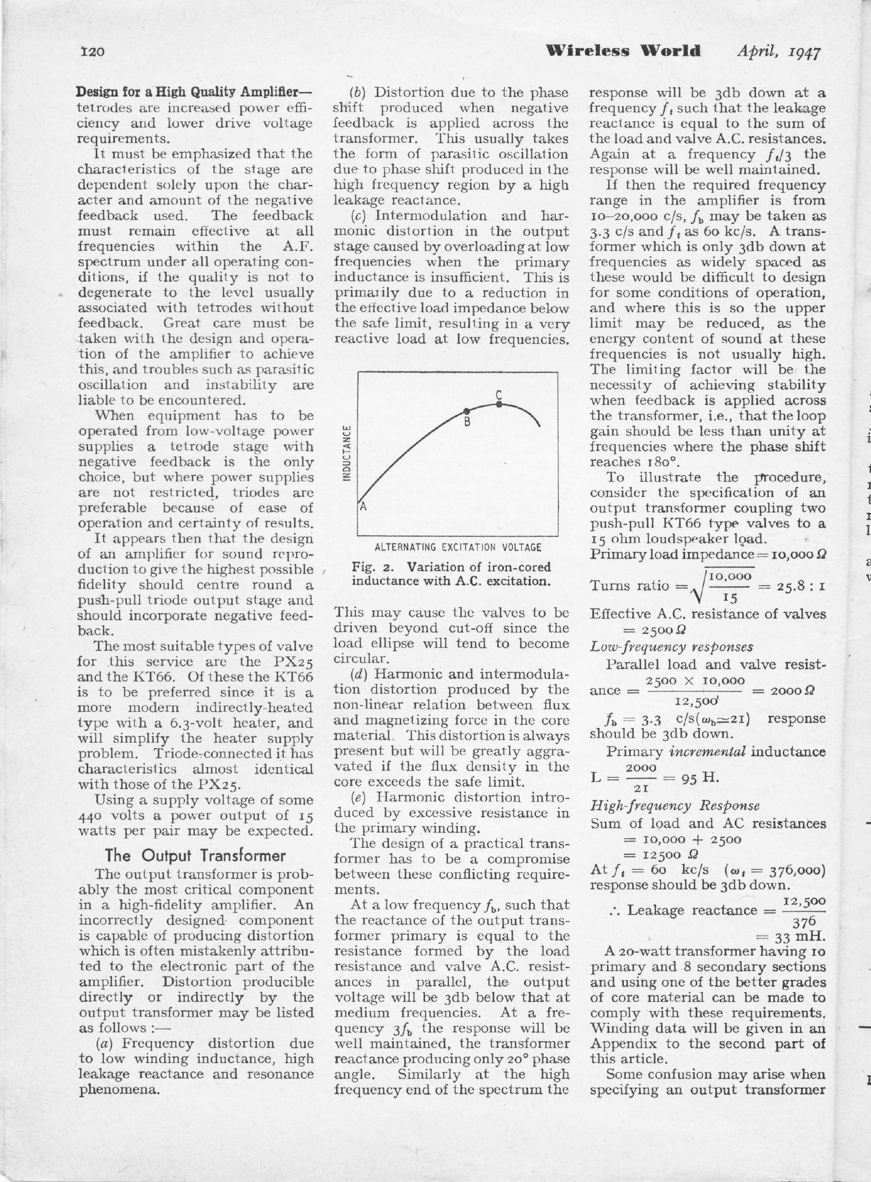
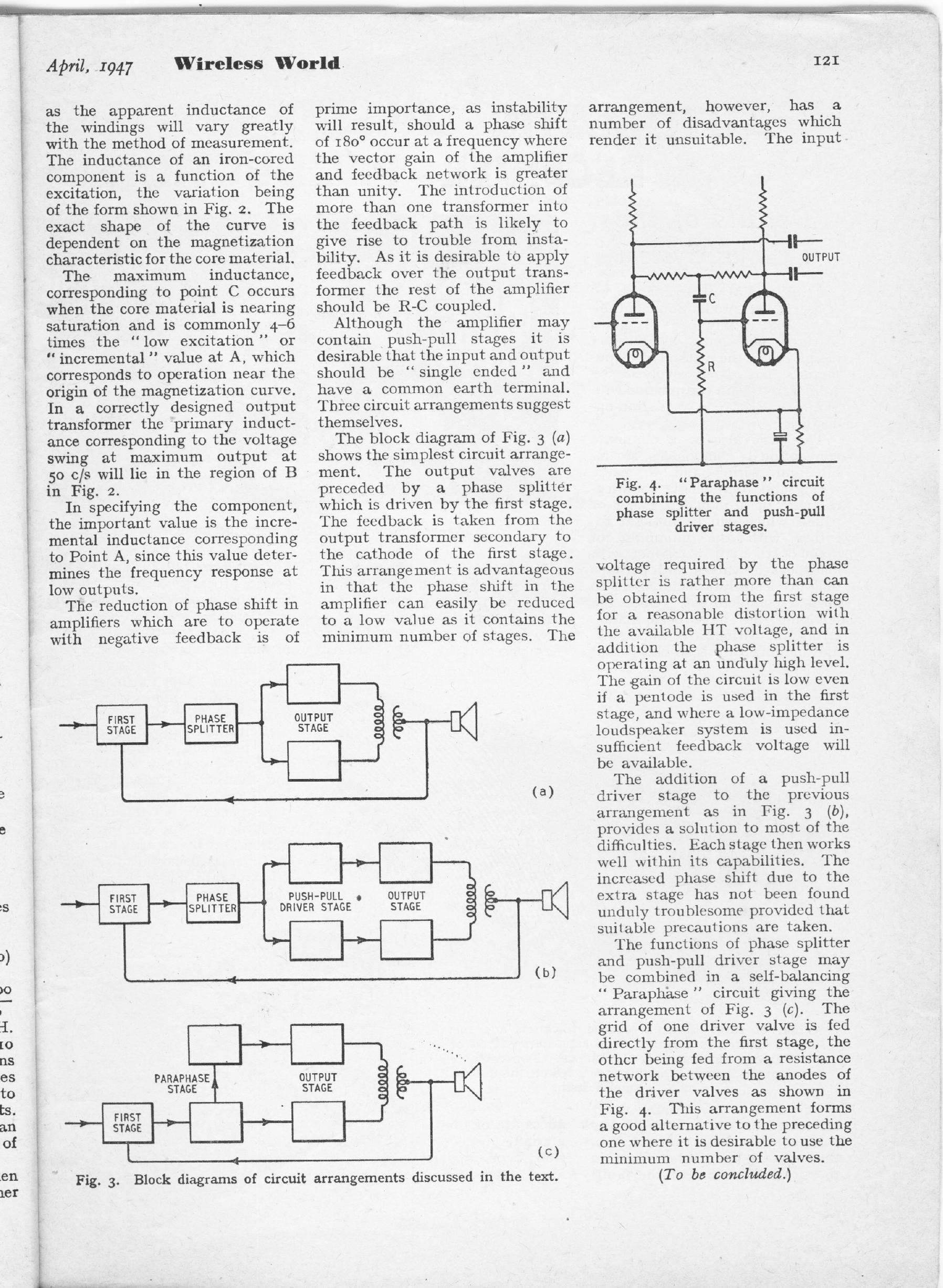
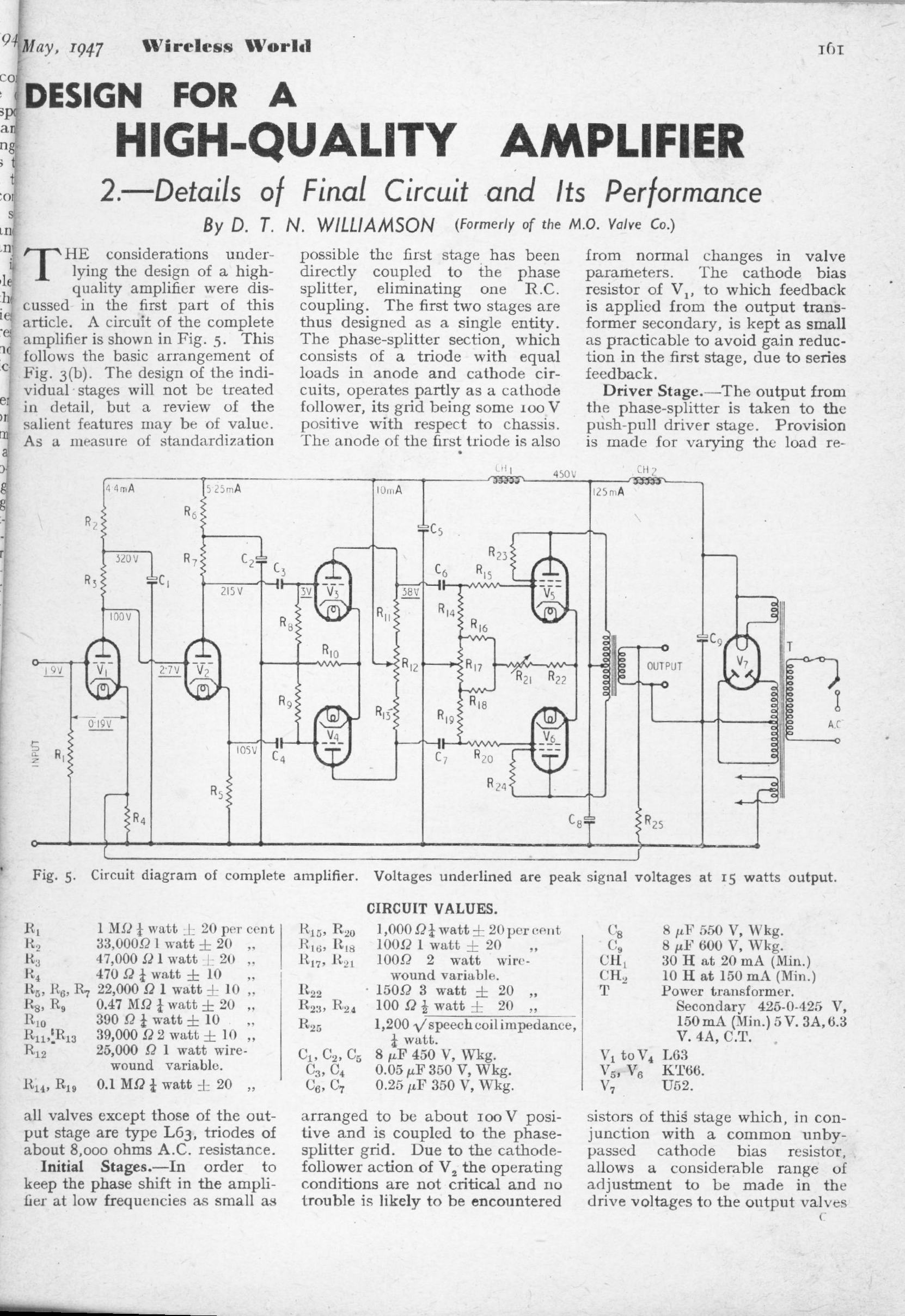
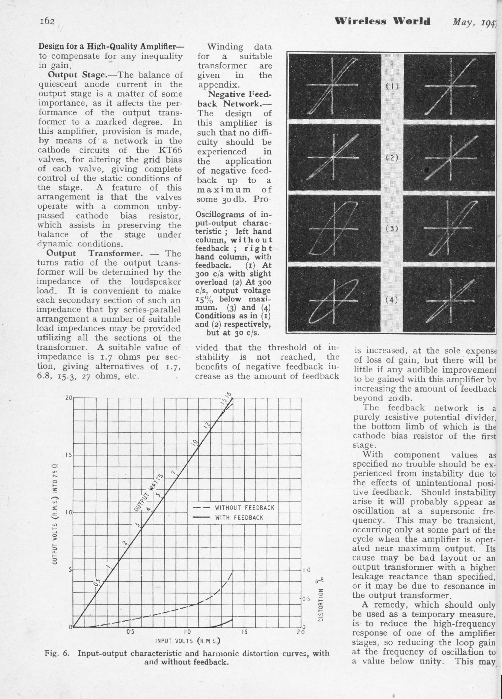
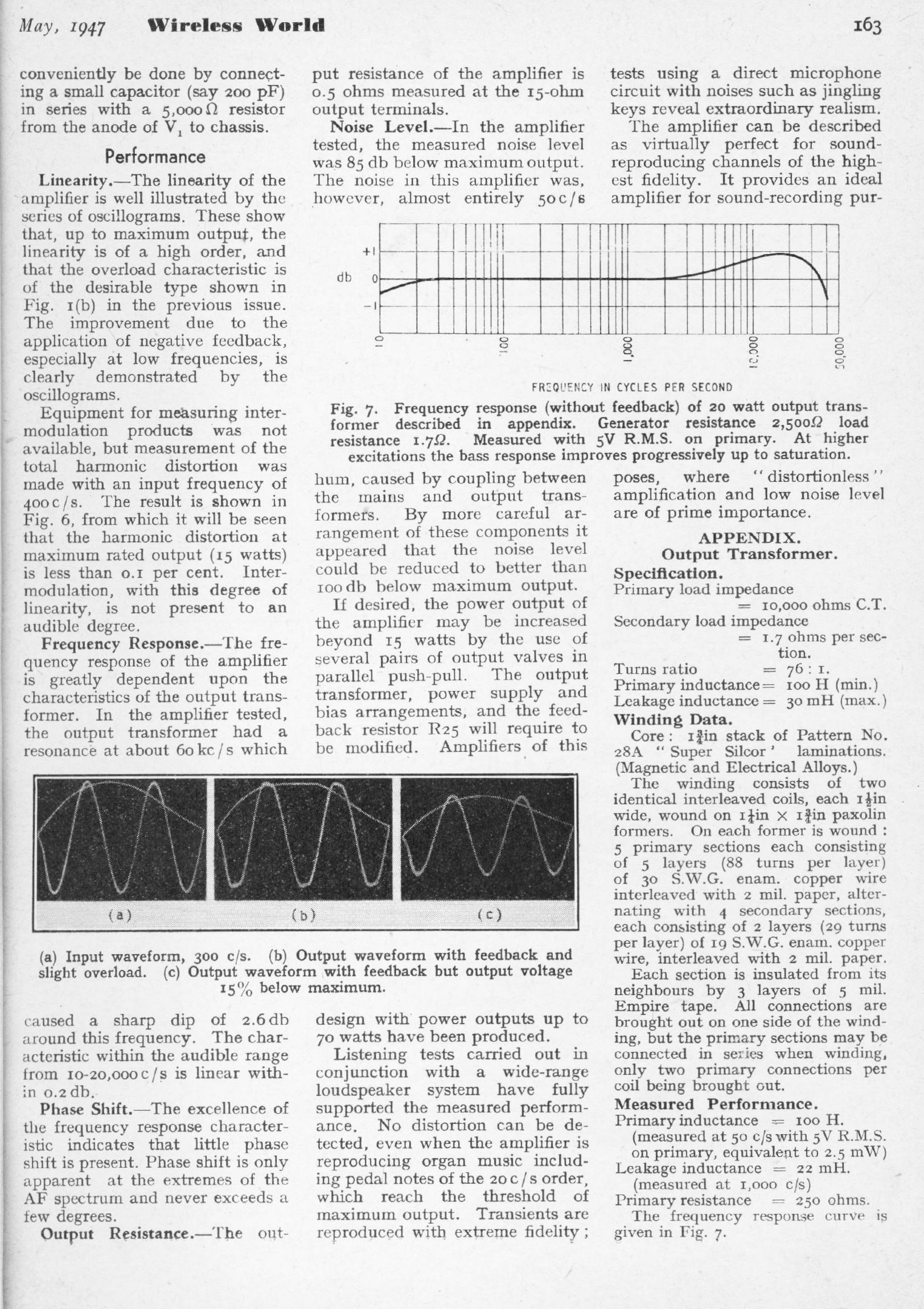
THE WILLIAMSON HIGH-QUALITY AMPLIFIER: Apr 1947
D T N Williamson
This amplifier was widely regarded as the best design available for home construction at the time. However there were persistent reports that it was unduly prone to high-frequency instability.
|
| |||||
|
|
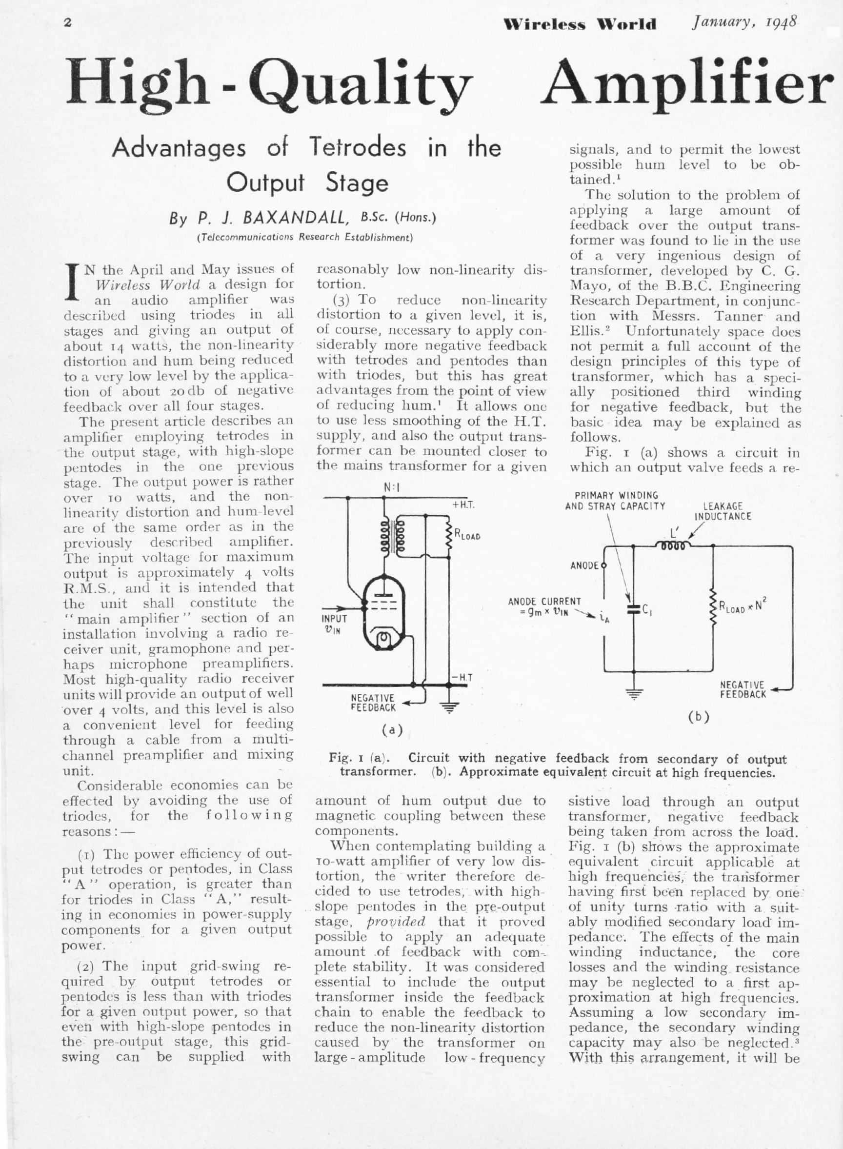
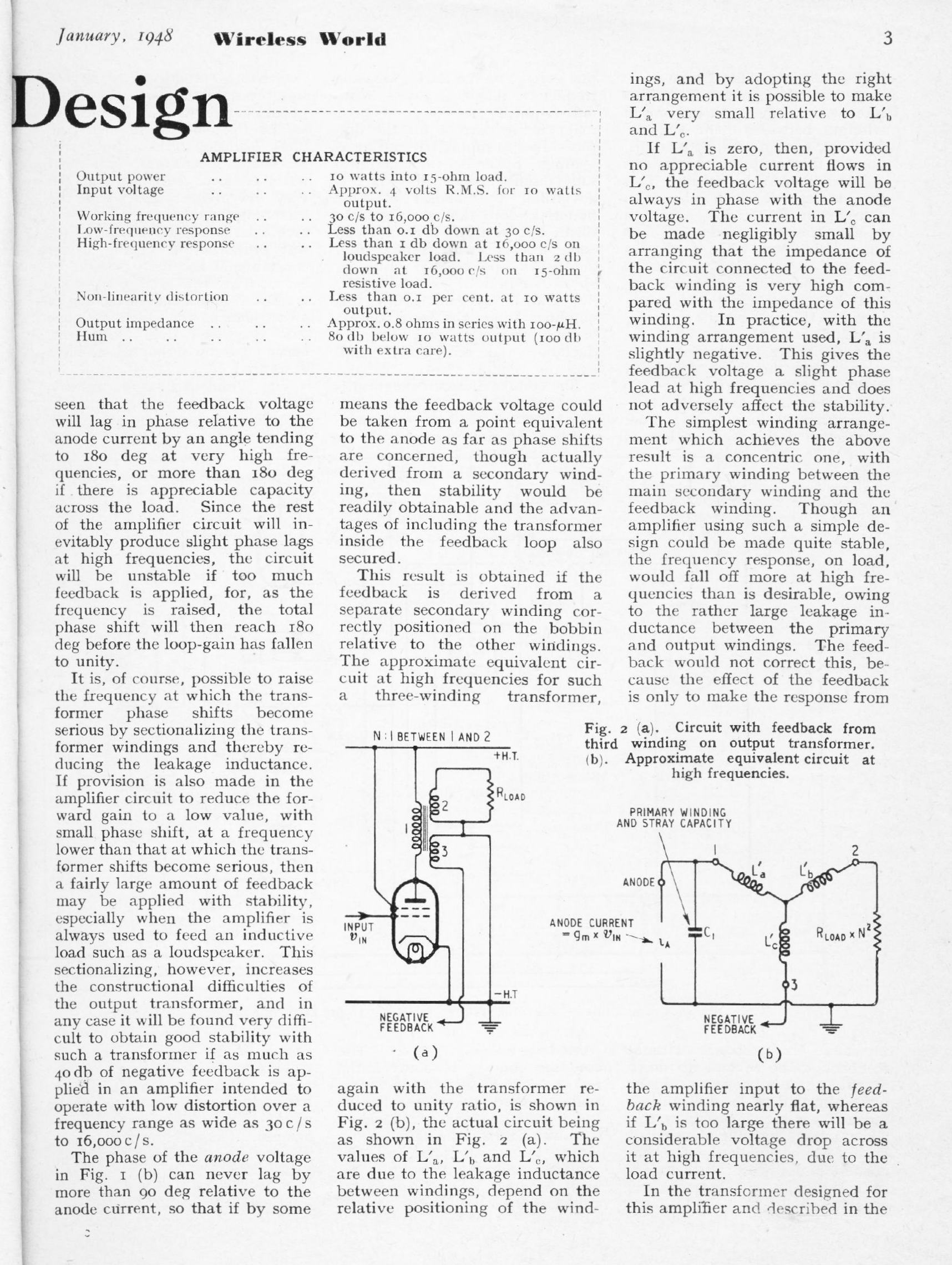
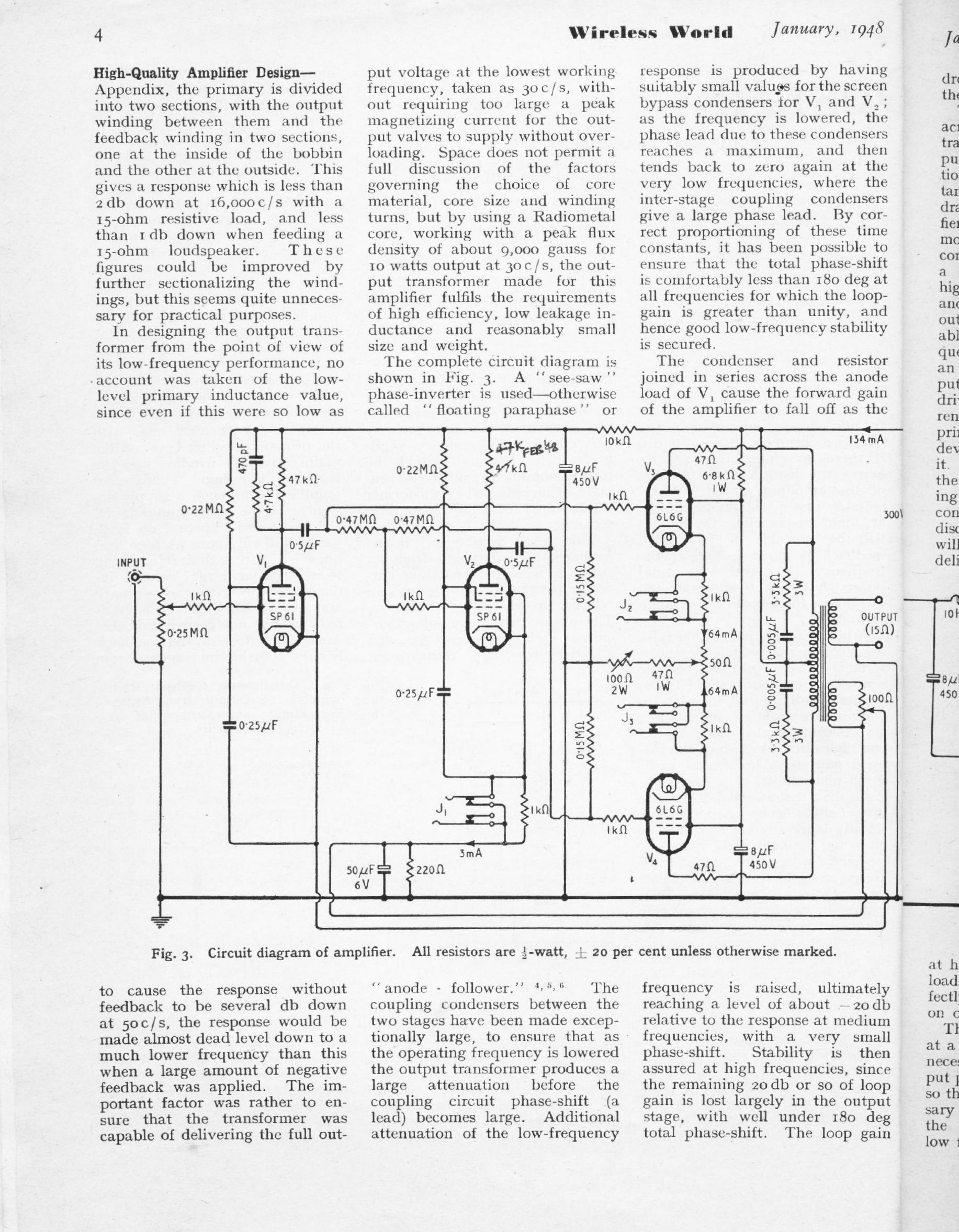
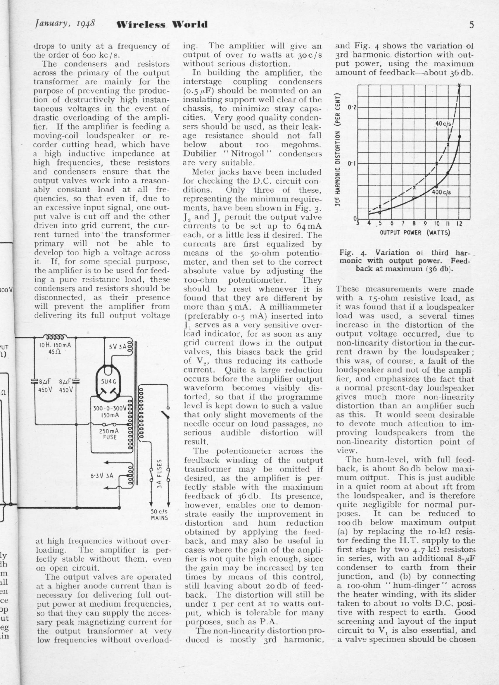
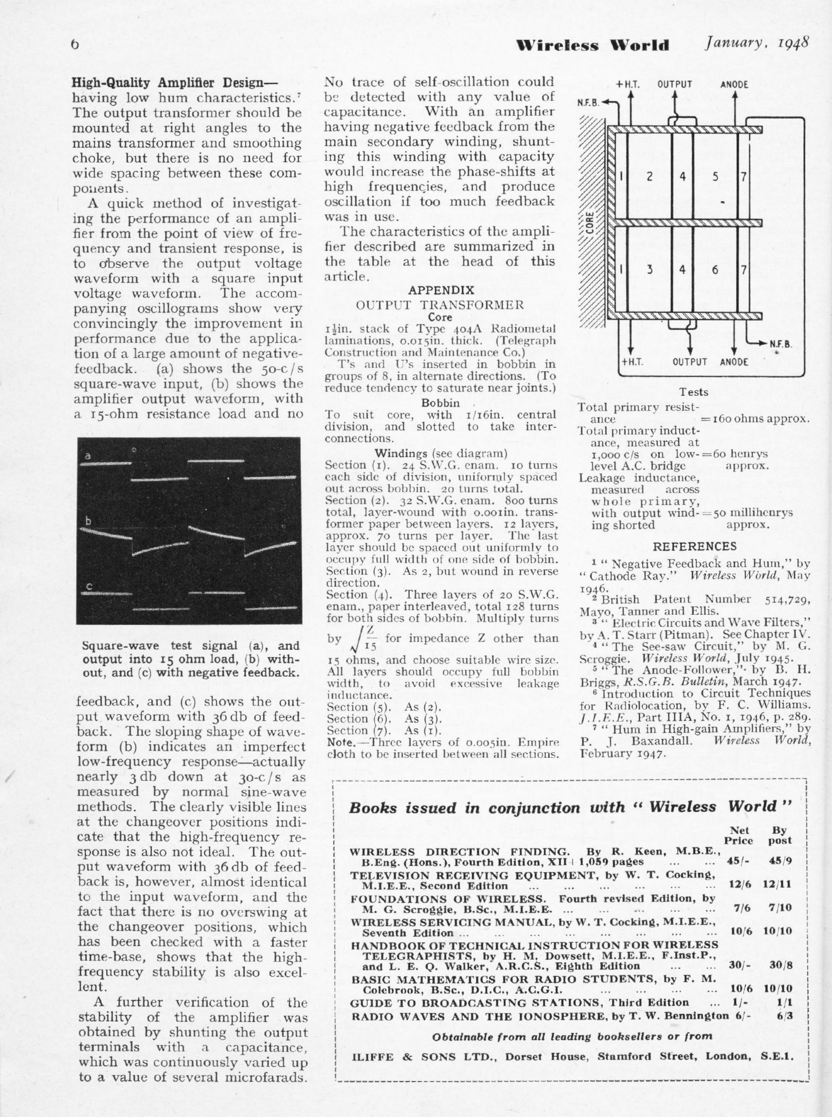
HIGH-QUALITY AMPLIFIER DESIGN: Jan 1948
Peter Baxandall
|
|
|
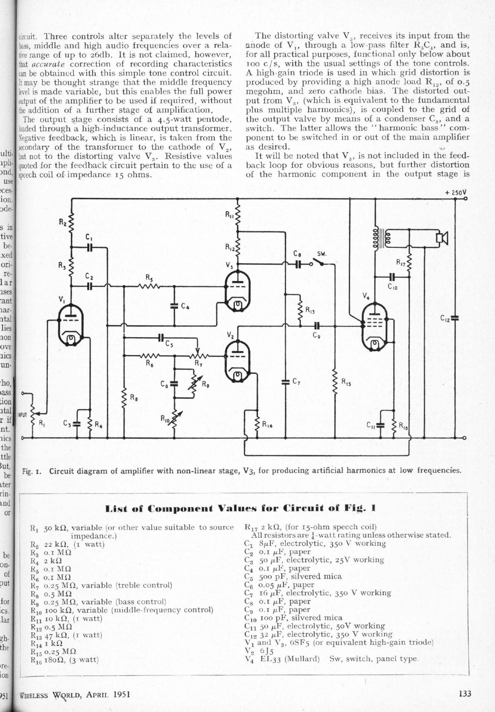
BASS WITHOUT BIG BAFFLES: Apr 1951
K A Exley
The idea is to generate a "synthetic bass" by adding distortion to the audio frequencies below 100 Hz, the statement being made that this increases the subjective volume of the fundamental. WW was already much occupied with "high-fidelity" at this time, and the idea of adding extra distortion- because valve amplifiers already produced plenty- was not enthusiatically received by the majority of readers.
|
|
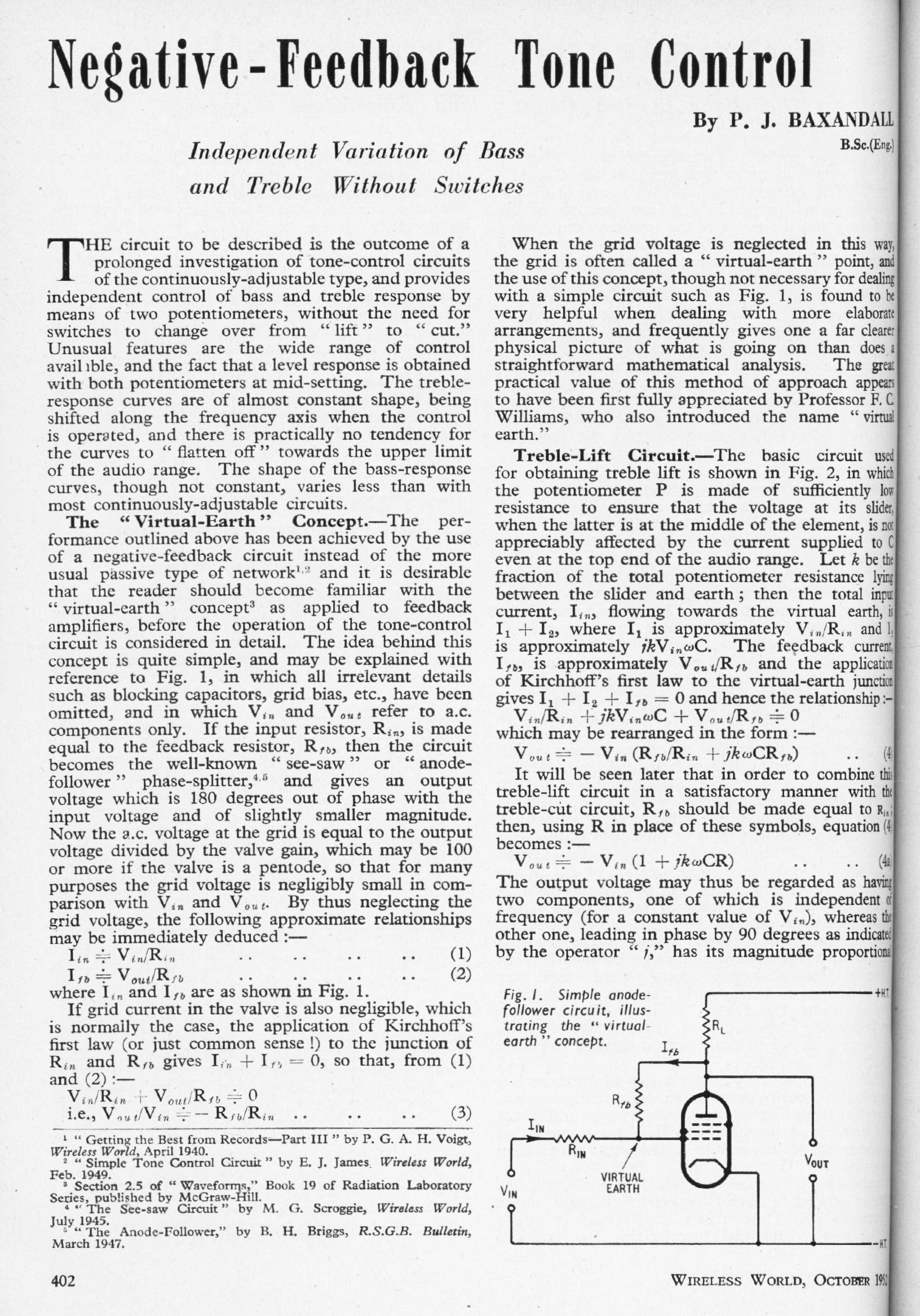
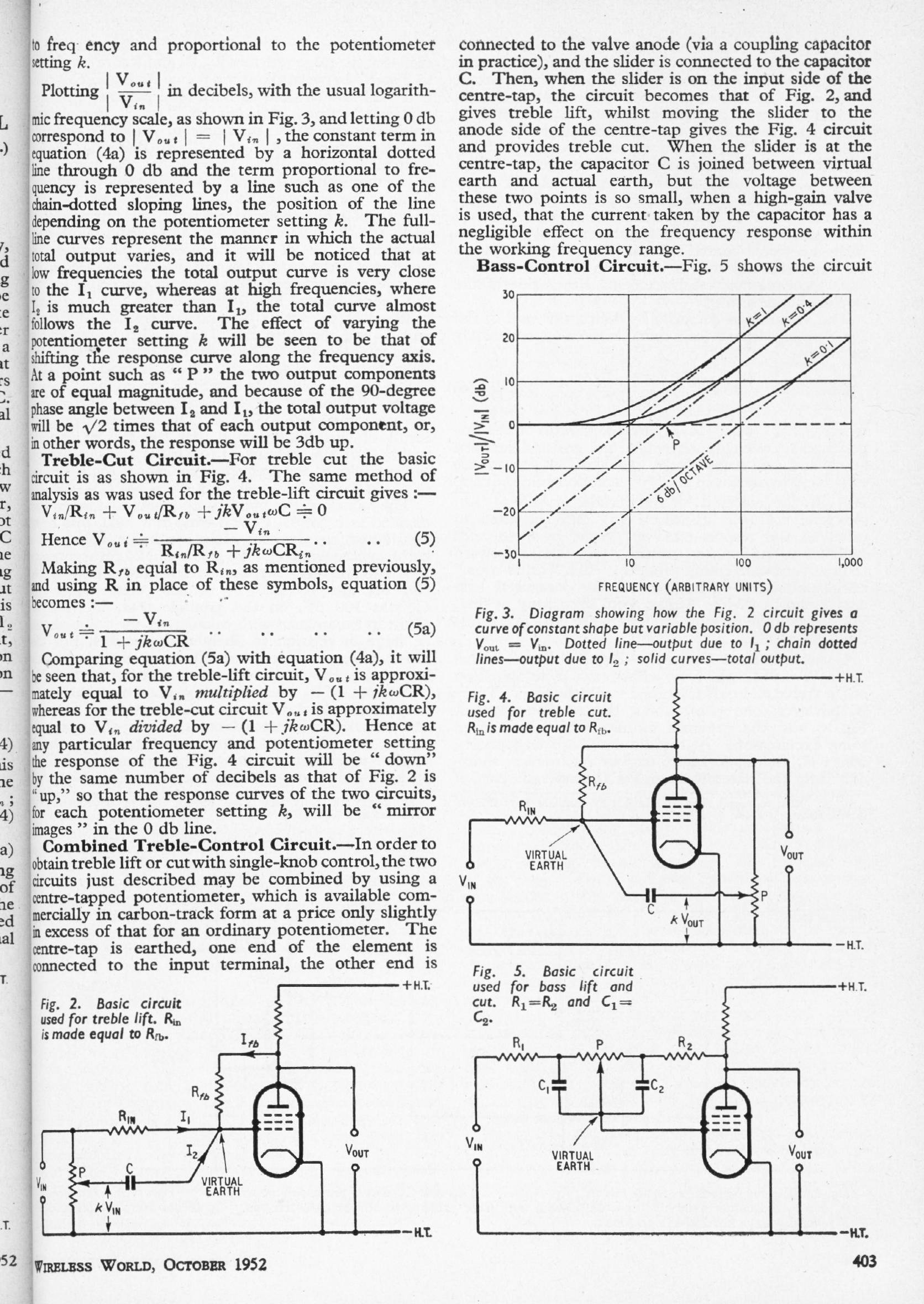
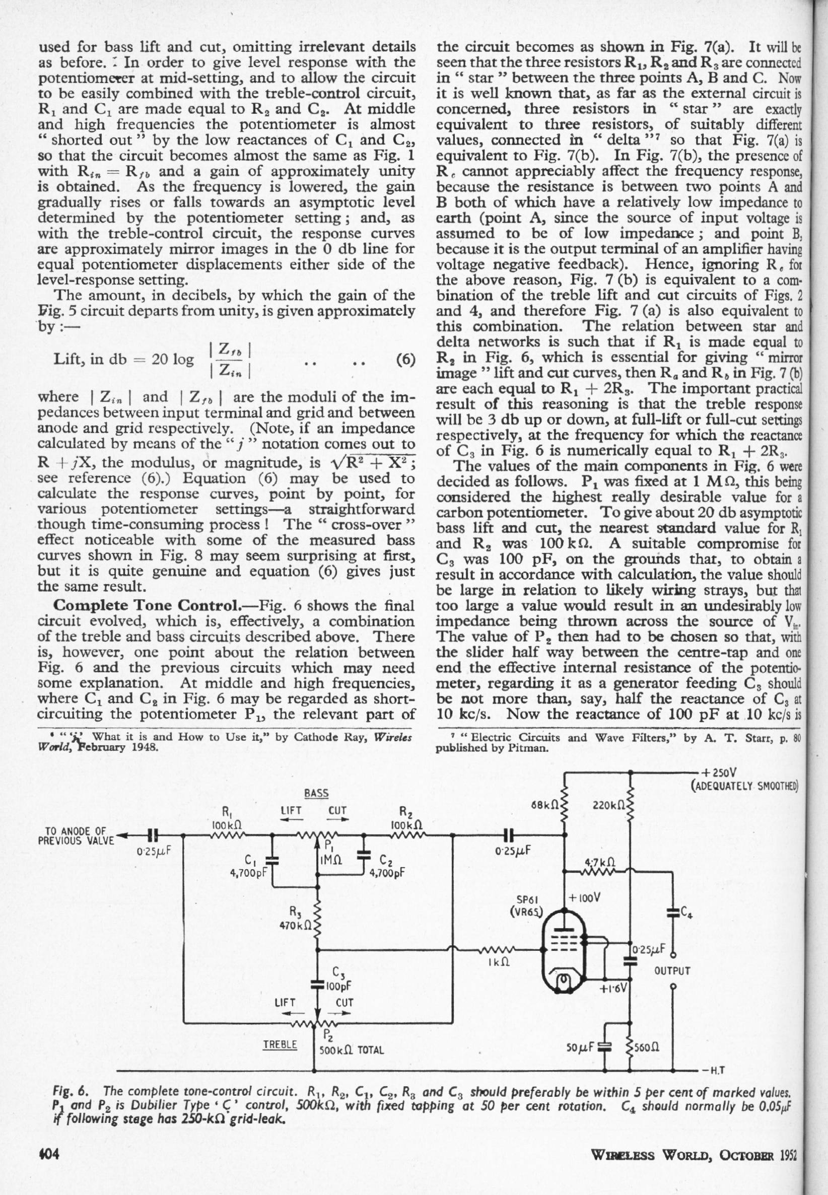
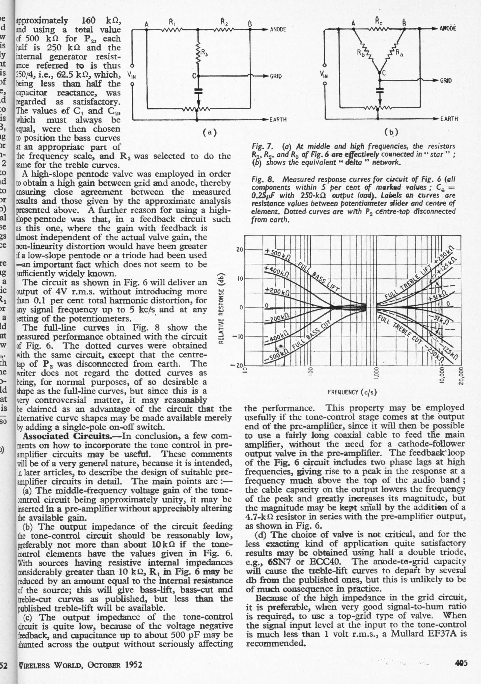
NEGATIVE-FEEDBACK TONE-CONTROL: Oct 1952
Peter J Baxandall
The famous Baxandall tone-control article. Note that the original version used a treble pot with a centre-tap; the simpler version universally adopted omits this. The resulting standard Baxandall circuit has some interesting subtleties regarding its input impedances, which can be much lower than a quick inspection of the circuit suggests; these effects described in my slim monograph: Small Signal Audio Design
|
|
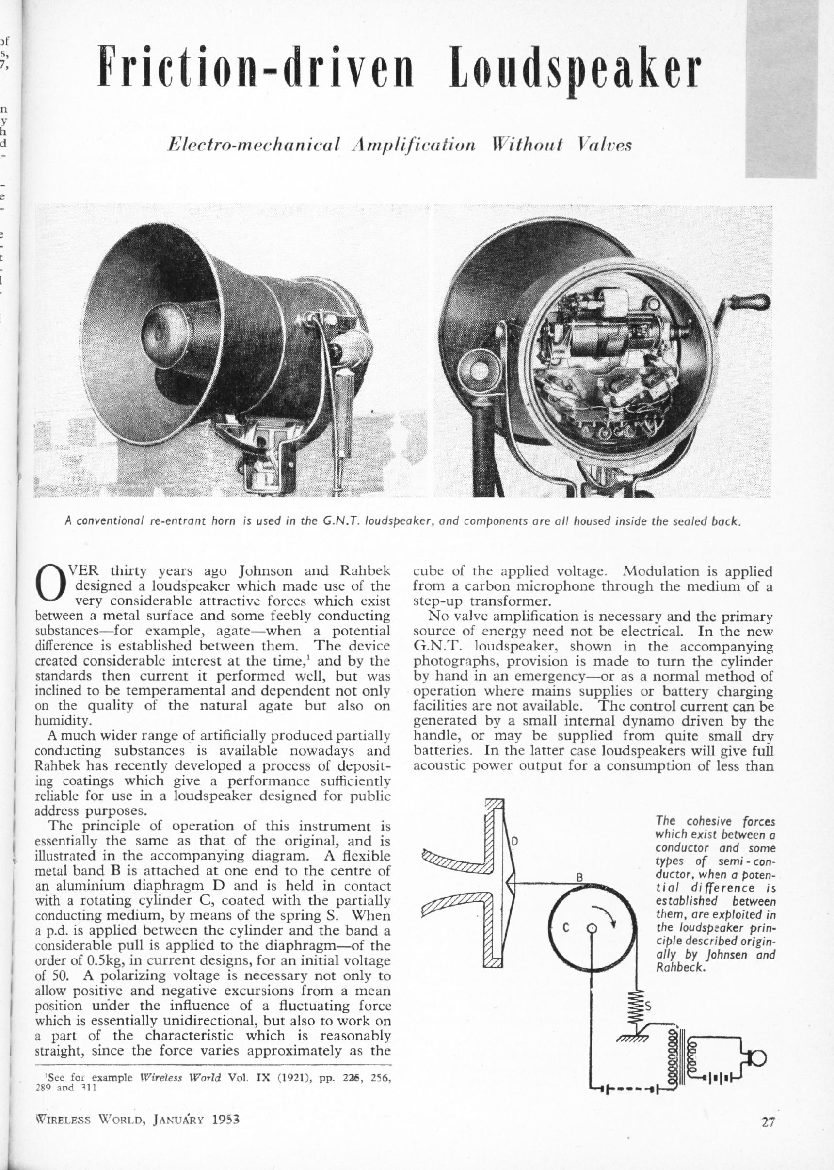
FRICTIONAL-DRIVE LOUDSPEAKERS: January 1953
Anon
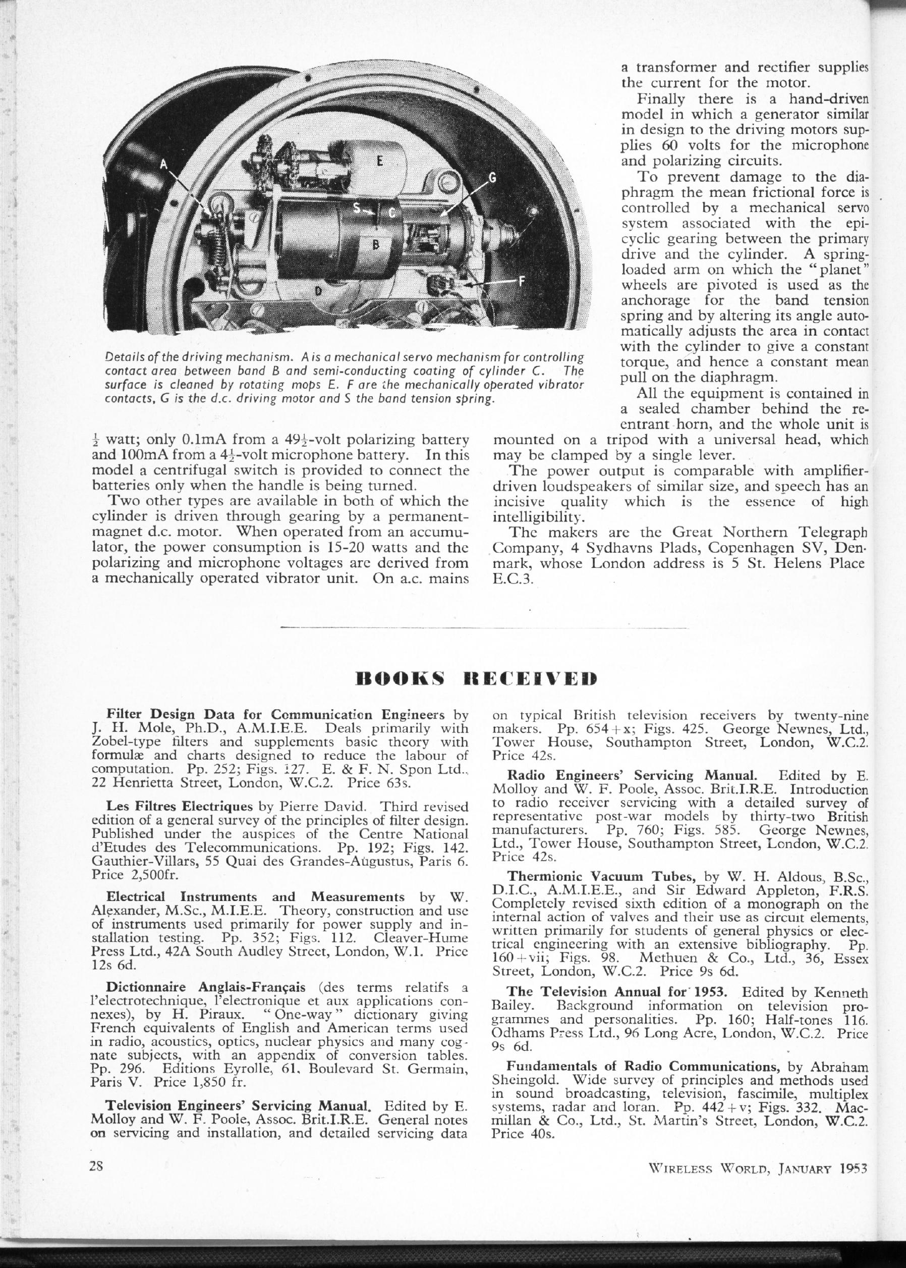
An unconventional loudspeaker is described with an amplifier that converts electrical signals into mechanical forces by voltage-controlled friction. Electrical power was needed both to run a carbon microphone and polarise the frictional element, but this could be provided by a dynamo attached to the same hand-crank that worked the frictional element. This surely must have been developed with nuclear war in mind.
|
HOME-MADE TRANSISTORS: January 1954
P B Helsdon
This remarkable article shows you how to make your own point-contact transistors by taking the innards of a germanium rectifier and adding two 'cat's-whiskers'to it. The point-contact transistor was the first type made, and it was not very satisfactory, having poor performance and being both delicate and unreliable. When the much-superior junction transistors (the type we use today) came along the point-contact version disappeared rapidly. Not even the most die-hard retro-audio enthusiast has asked for it to be brought back.
|
|
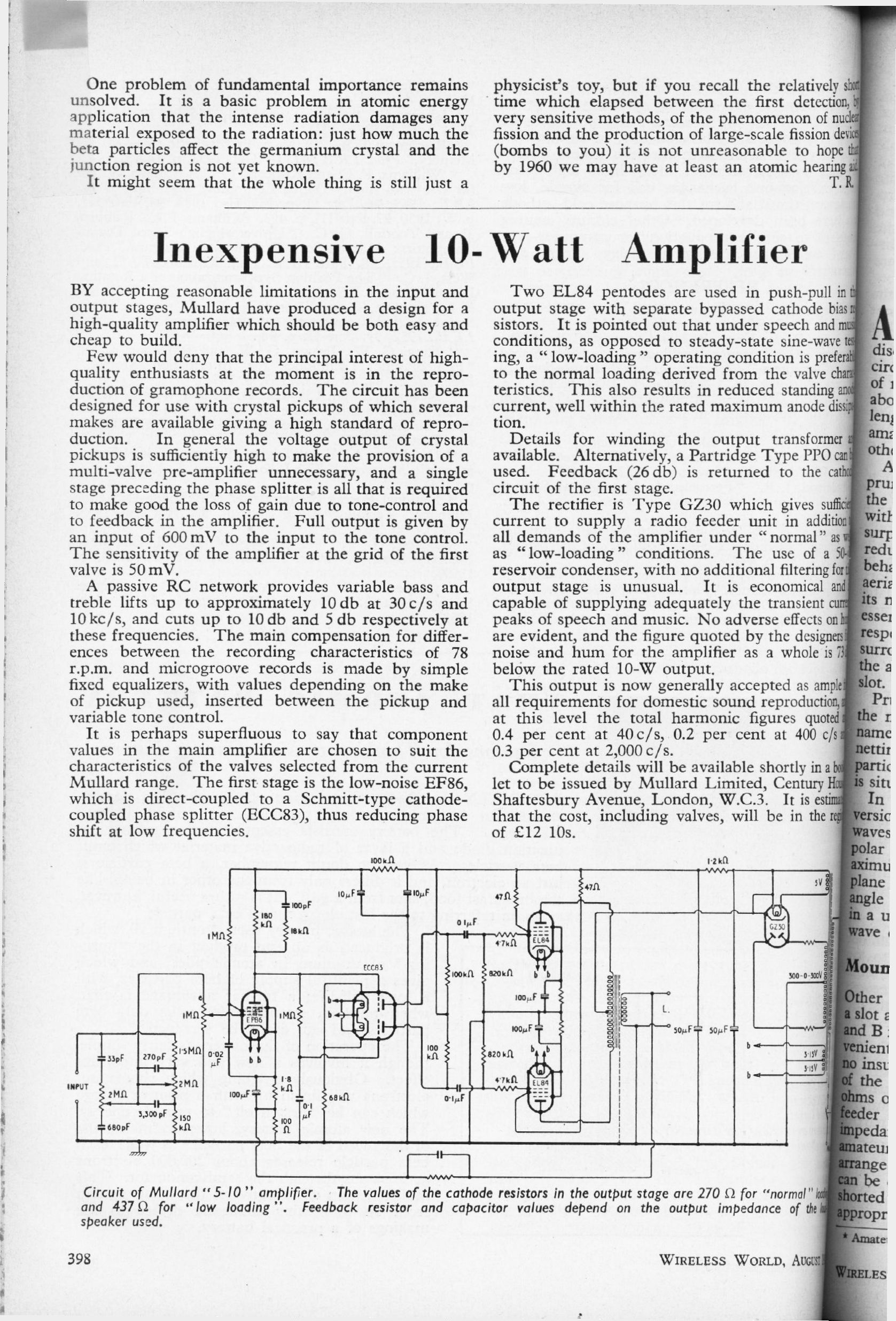
INEXPENSIVE 10W AMPLIFIER: August 1954
Author unknown (WW staff?)
|
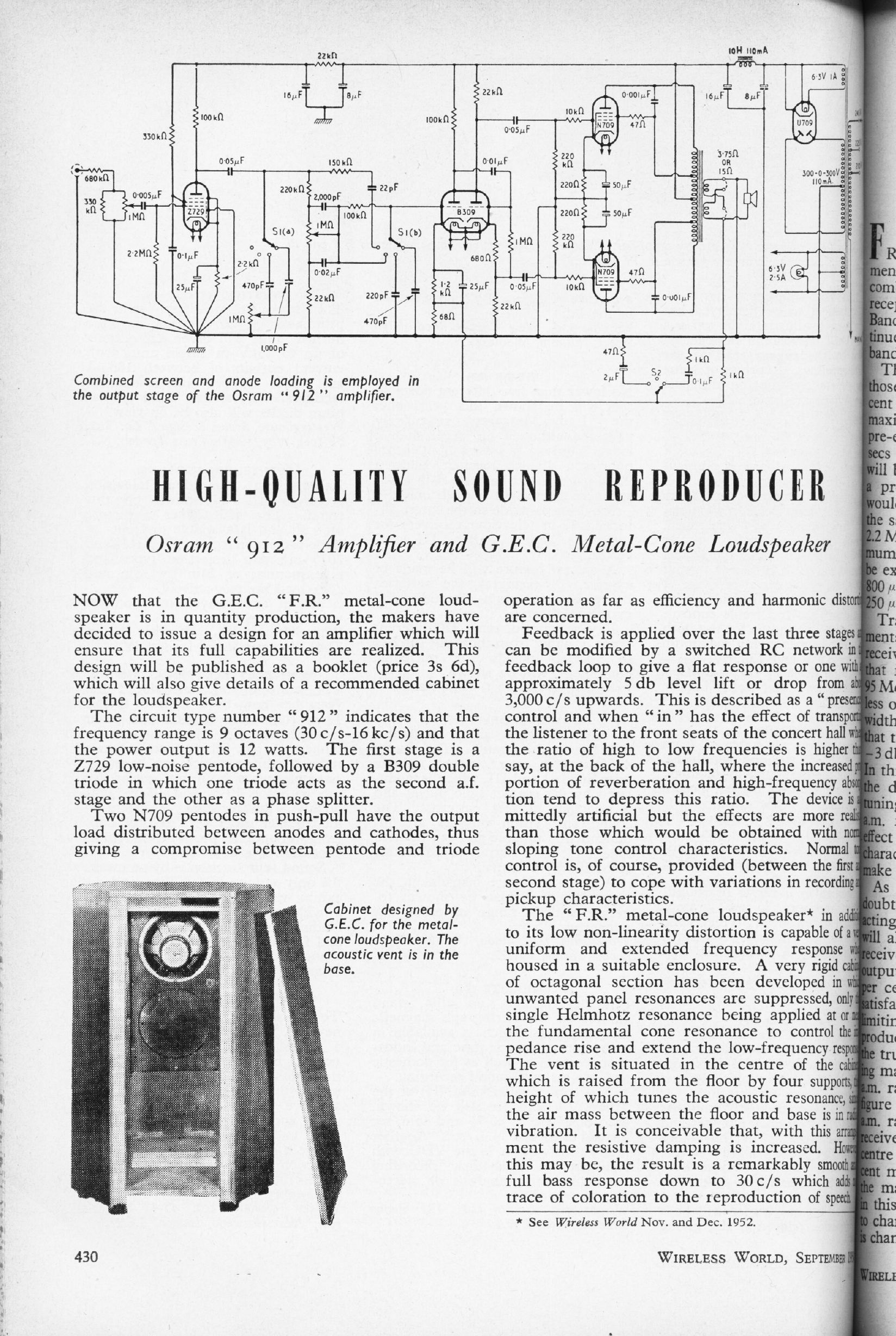
HIGH-QUALITY SOUND REPRODUCER: Sept 1954
Author unknown (WW staff?)
|
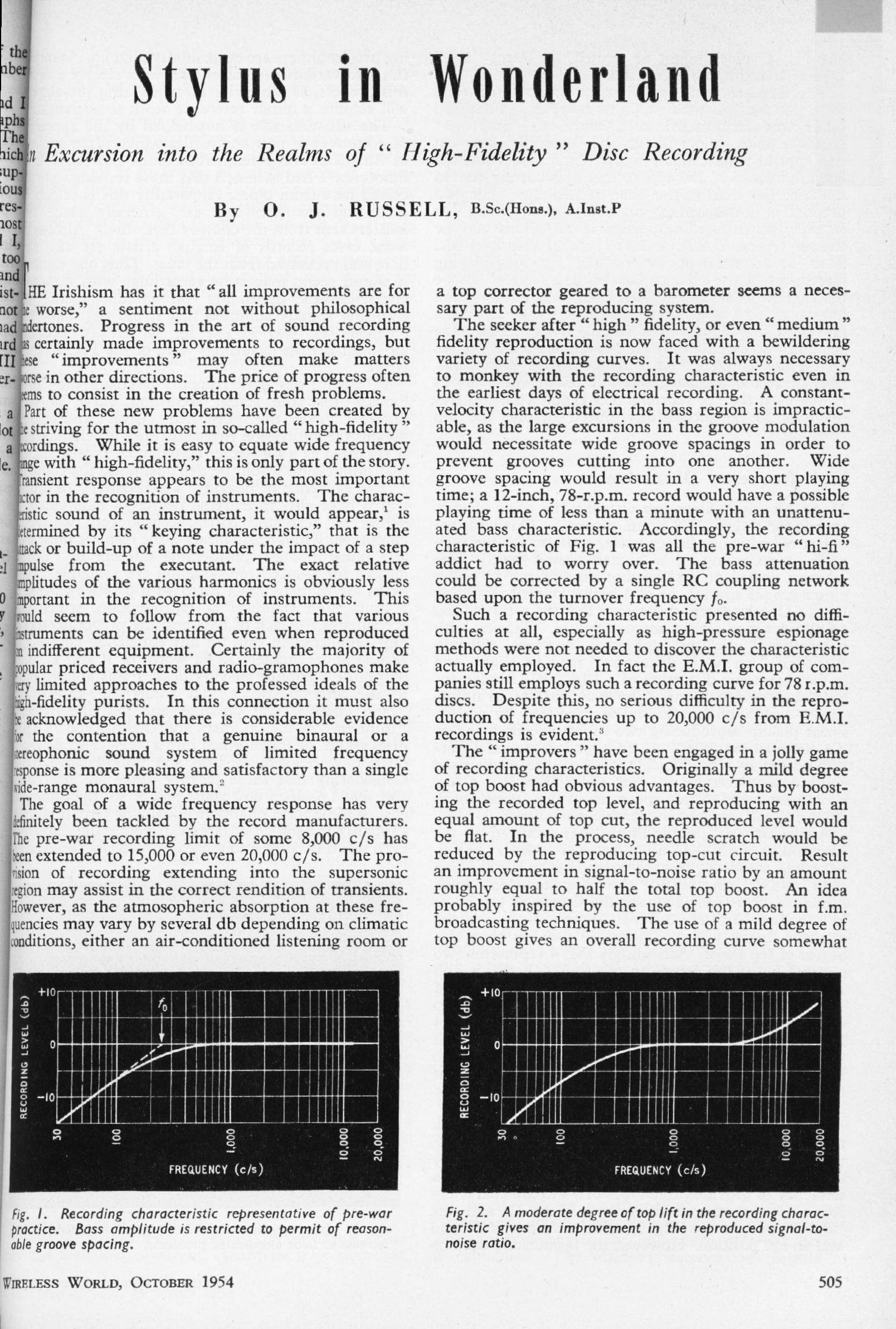
STYLUS IN WONDERLAND: Oct 1954
O J Russell
|
| ||||||
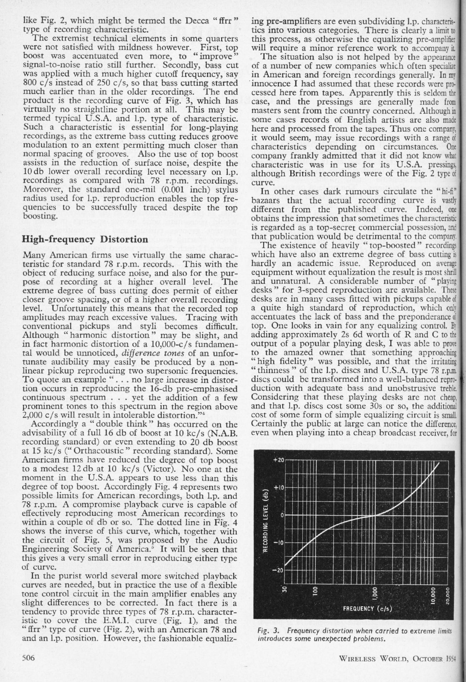
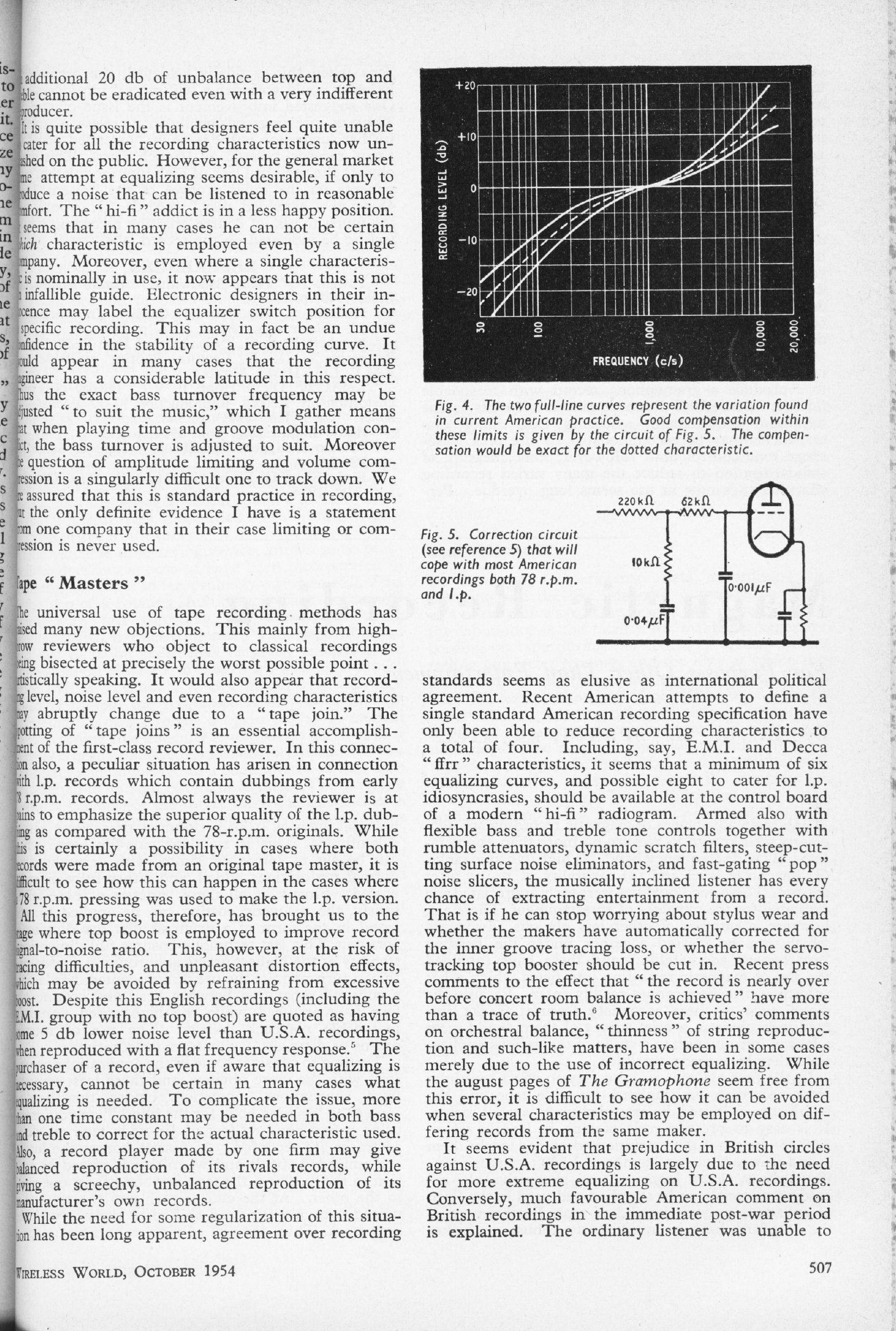
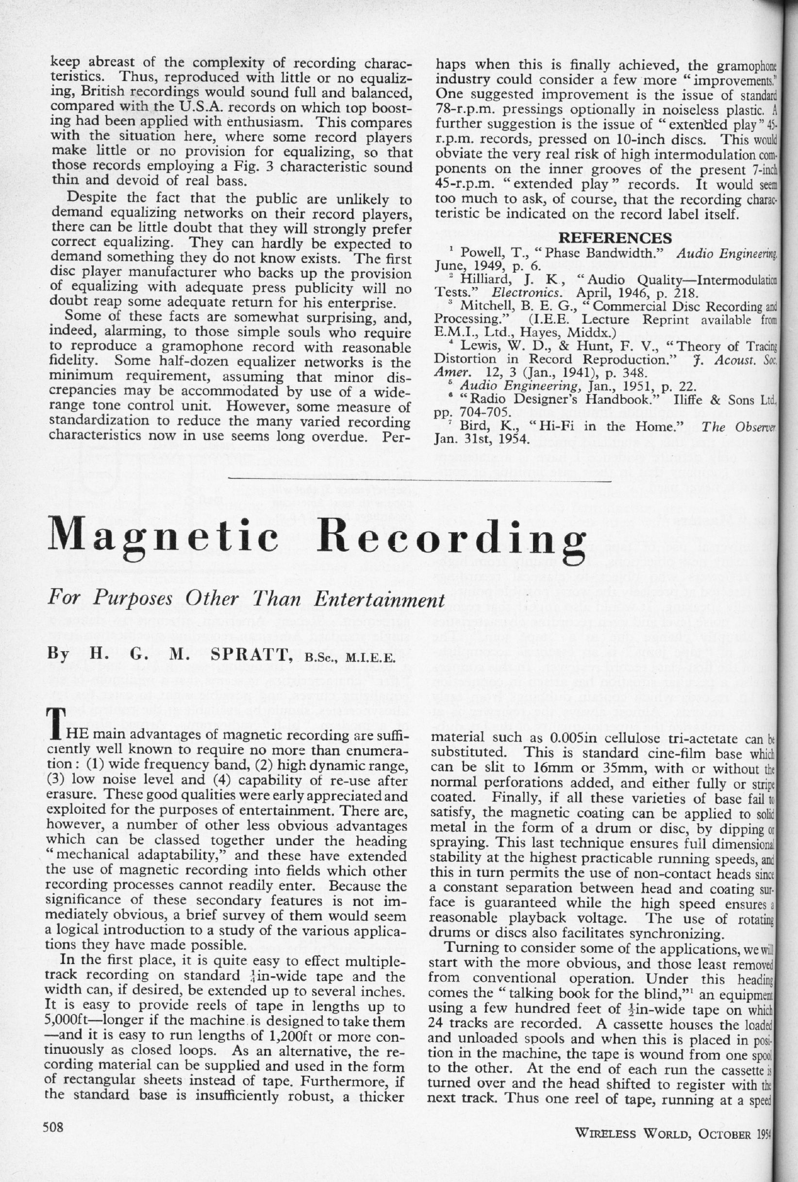
An examination of some of the problems involved in vinyl disc reproduction when a number of competing recording characteristics are in use. The author concludes that no less than six switchable equalisation option are required, plus minor tweaking from use of a "wide-range tone-control". Not a happy state of affairs. Standardisation on the RIAA characteristic was still two years away. | |||||||
INEXPENSIVE 10W AMPLIFIER COMMENTS: Oct 1954 and Dec 1954
| |||||
A letter from E F Good questioning some statements made about the 'Inexpensive 10W Amplifier' described above. Is the phase-splitter directly coupled? The designers reply. There is an intriguing reference to a tertiary-winding feedback system published by Peter Baxandall in WW. (January 1948) This article is now in the archive.Lower right on the original page is a correction to the 10W amplifier circuit, and also a correction to the 'High-quality Sound Reproducer' circuit published in September 1954. | A letter from F B White on coupling methods in the amplifier, with another tantalising reference to a tertiary-winding feedback system; the implication is that it was publicised by Peter Baxandall but he was not the patent holder. According to JLH the inventor was C G Mayo of the BBC Research Department. Note the significant reference to stability problems with the Williamson amplifier.Mid-left on the original page is a letter from Peter Walker pointing out that he drew attention to the so-called ultra-linear output configuration as long ago as 1943. |
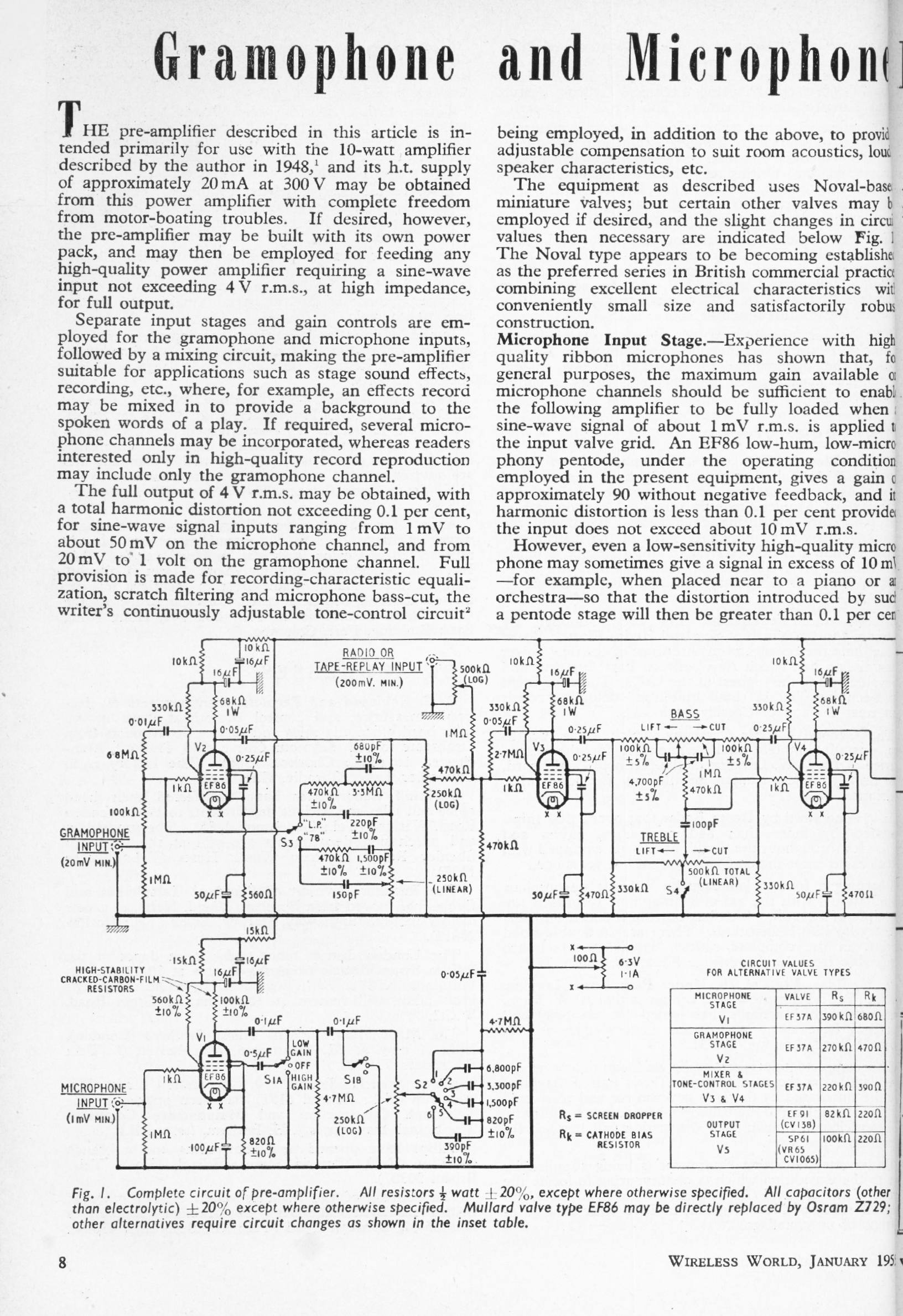
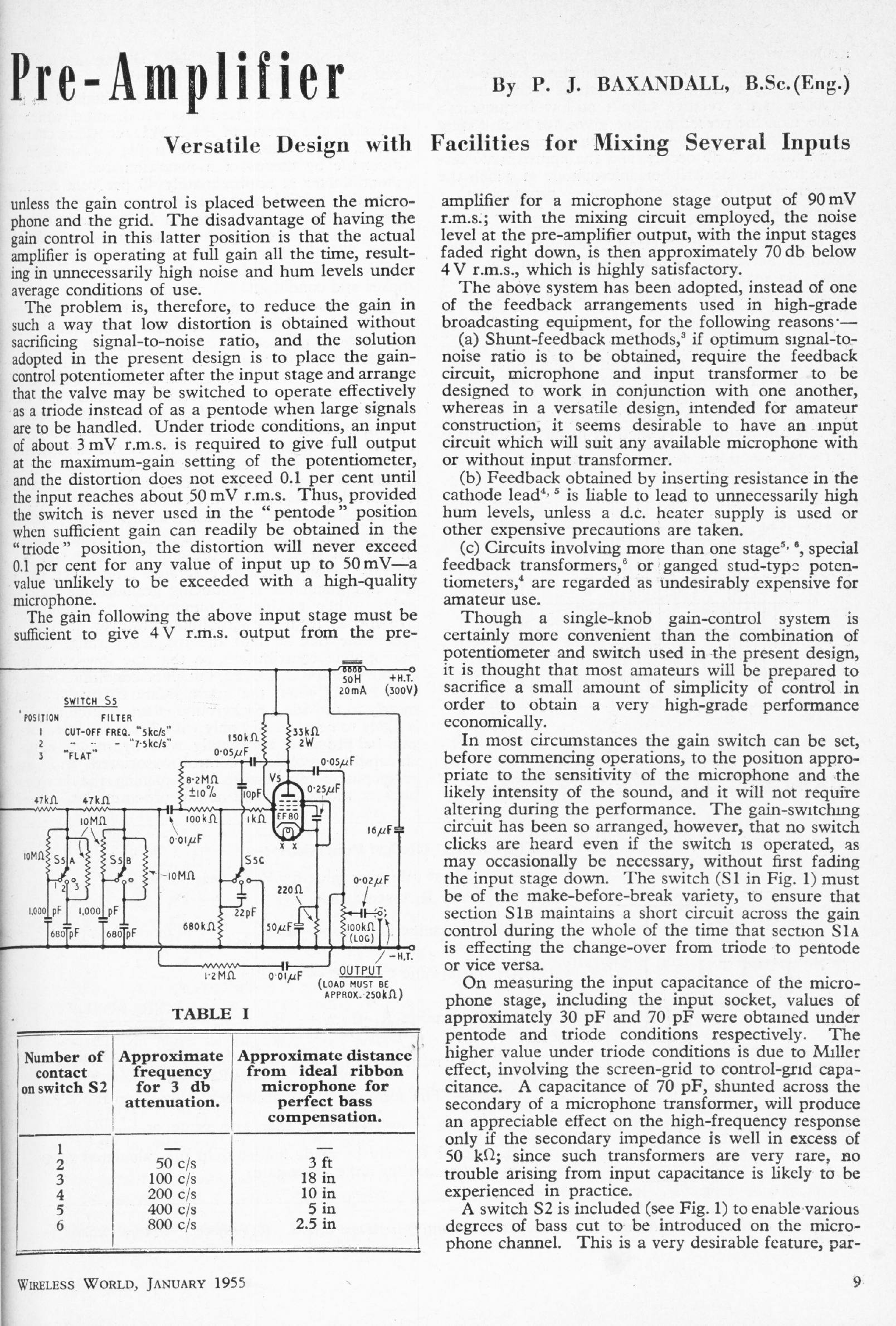
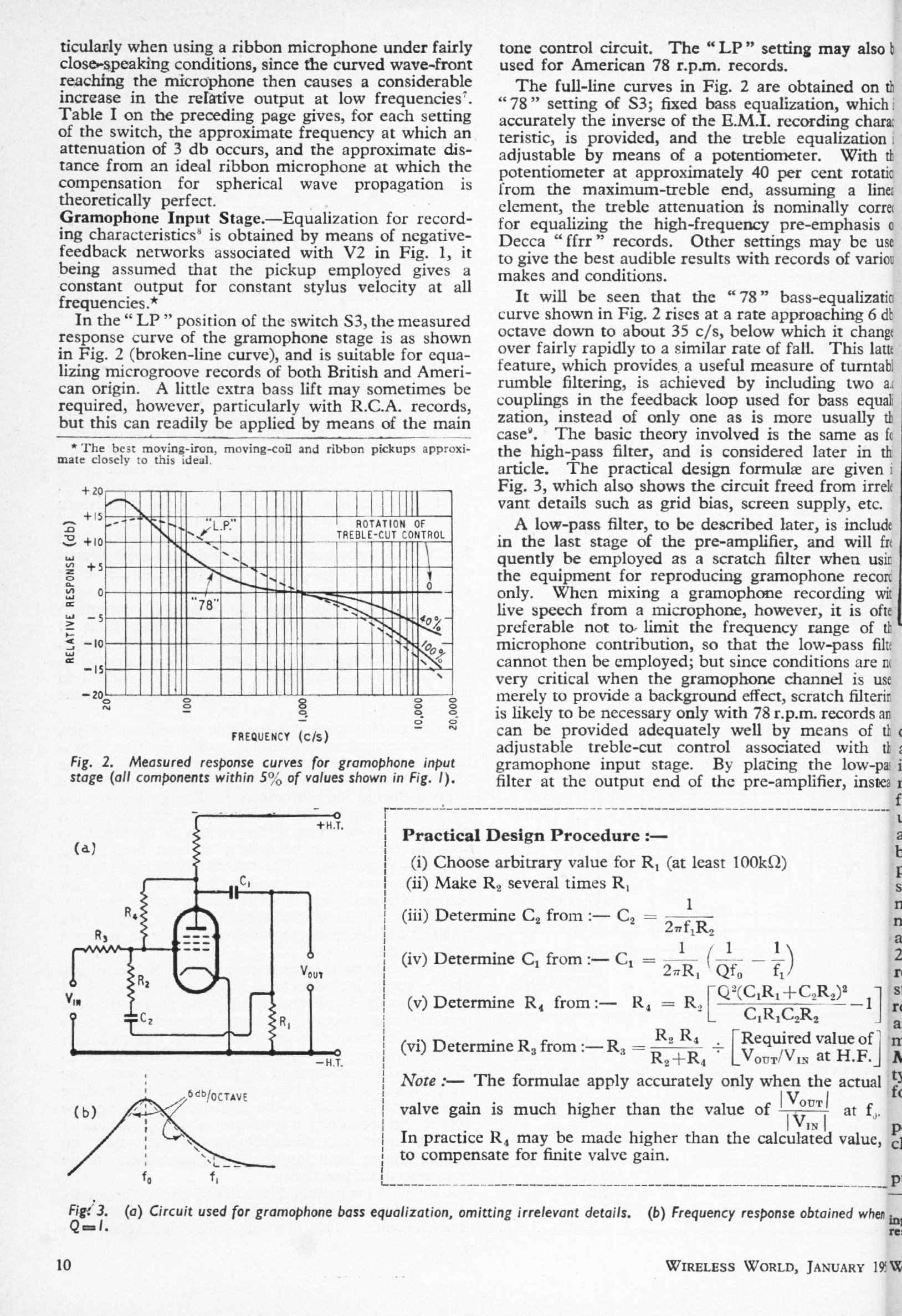
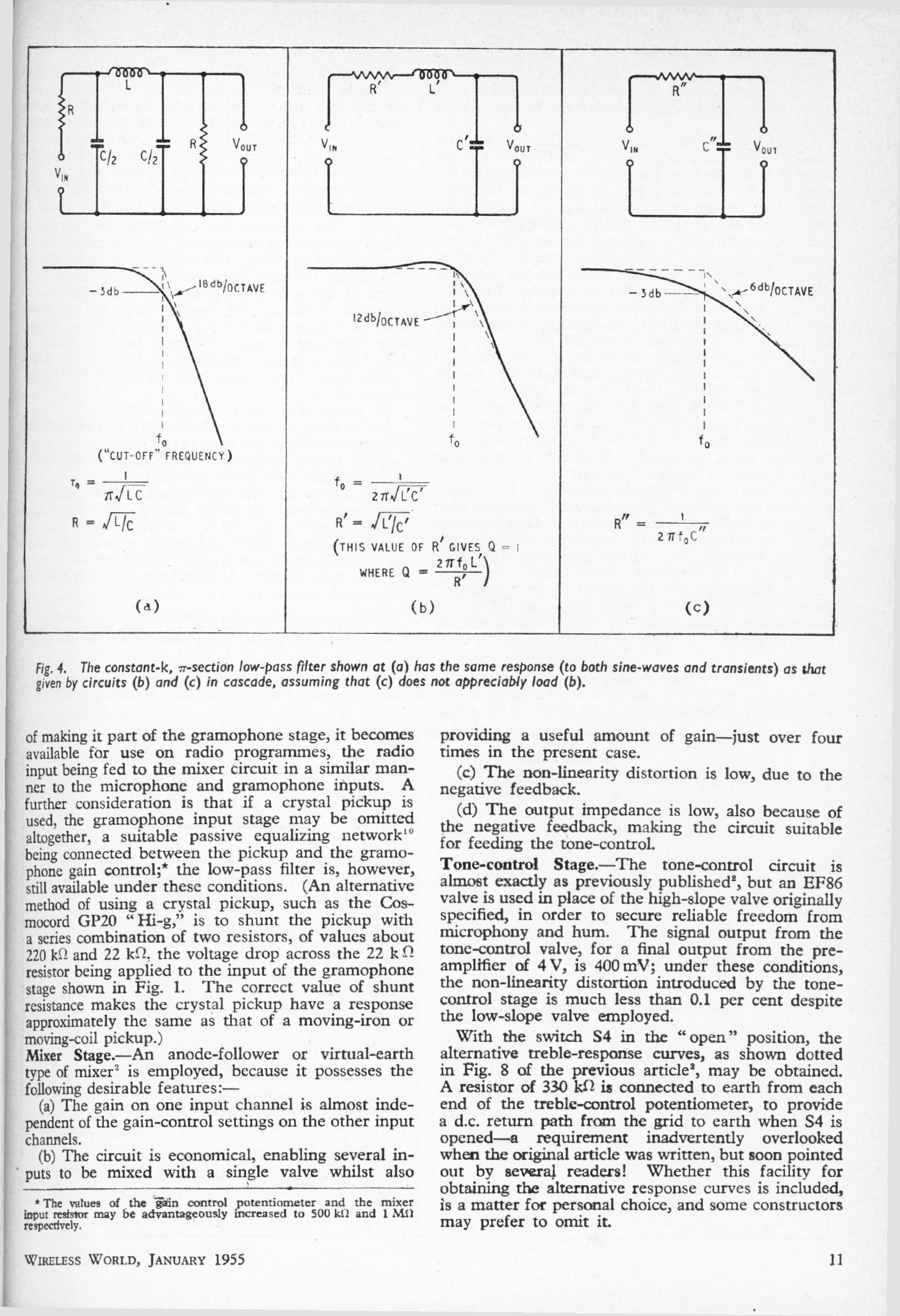
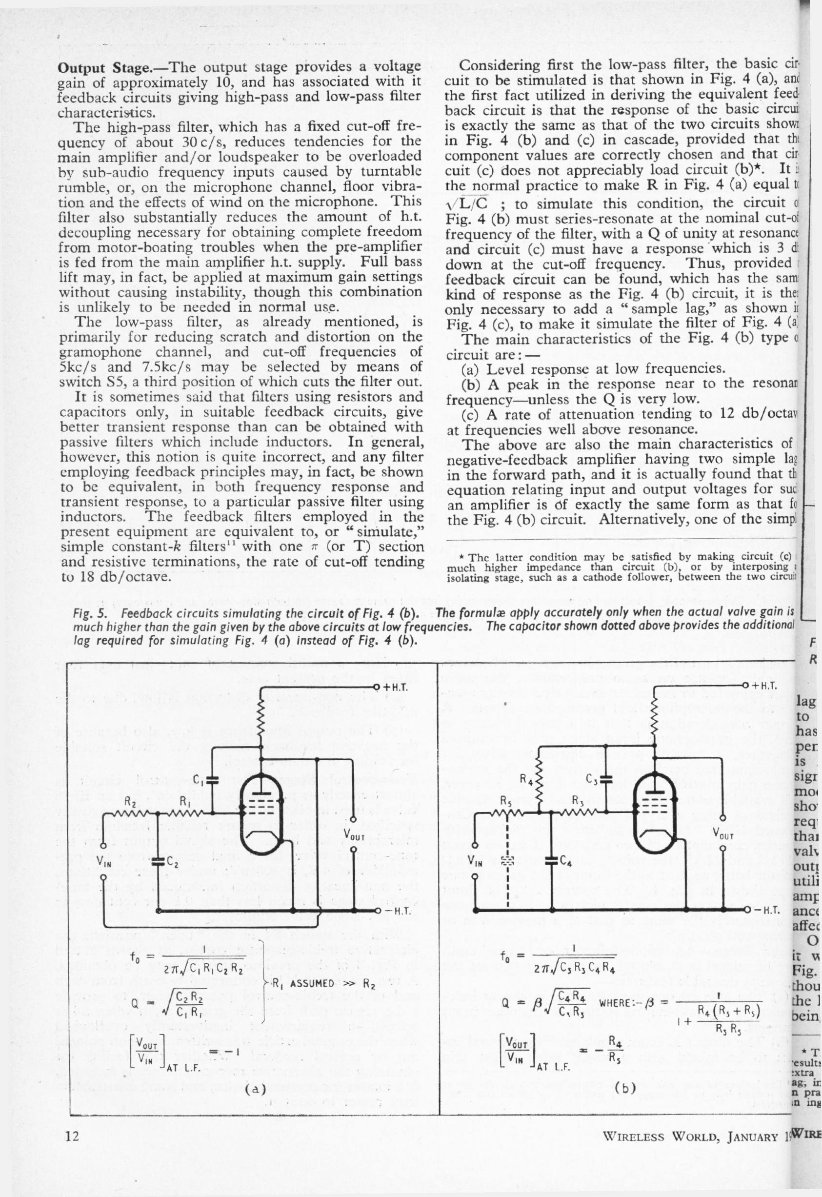
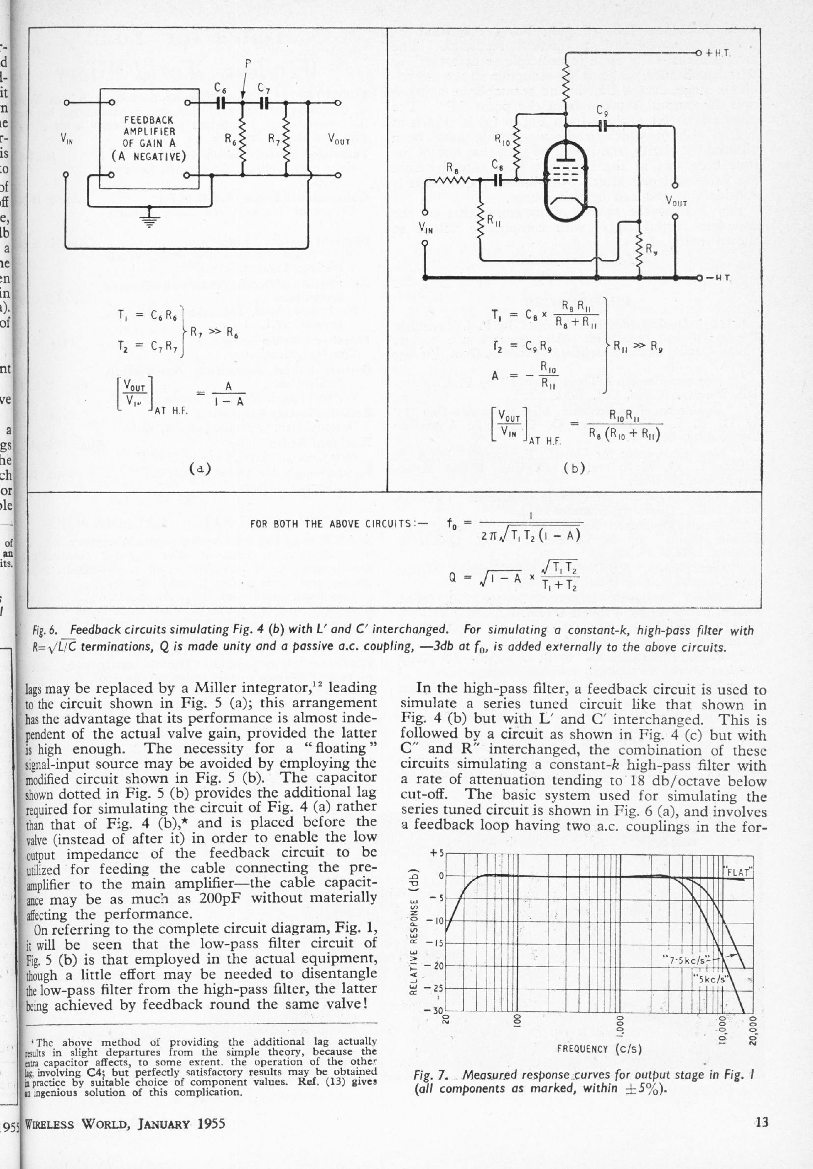
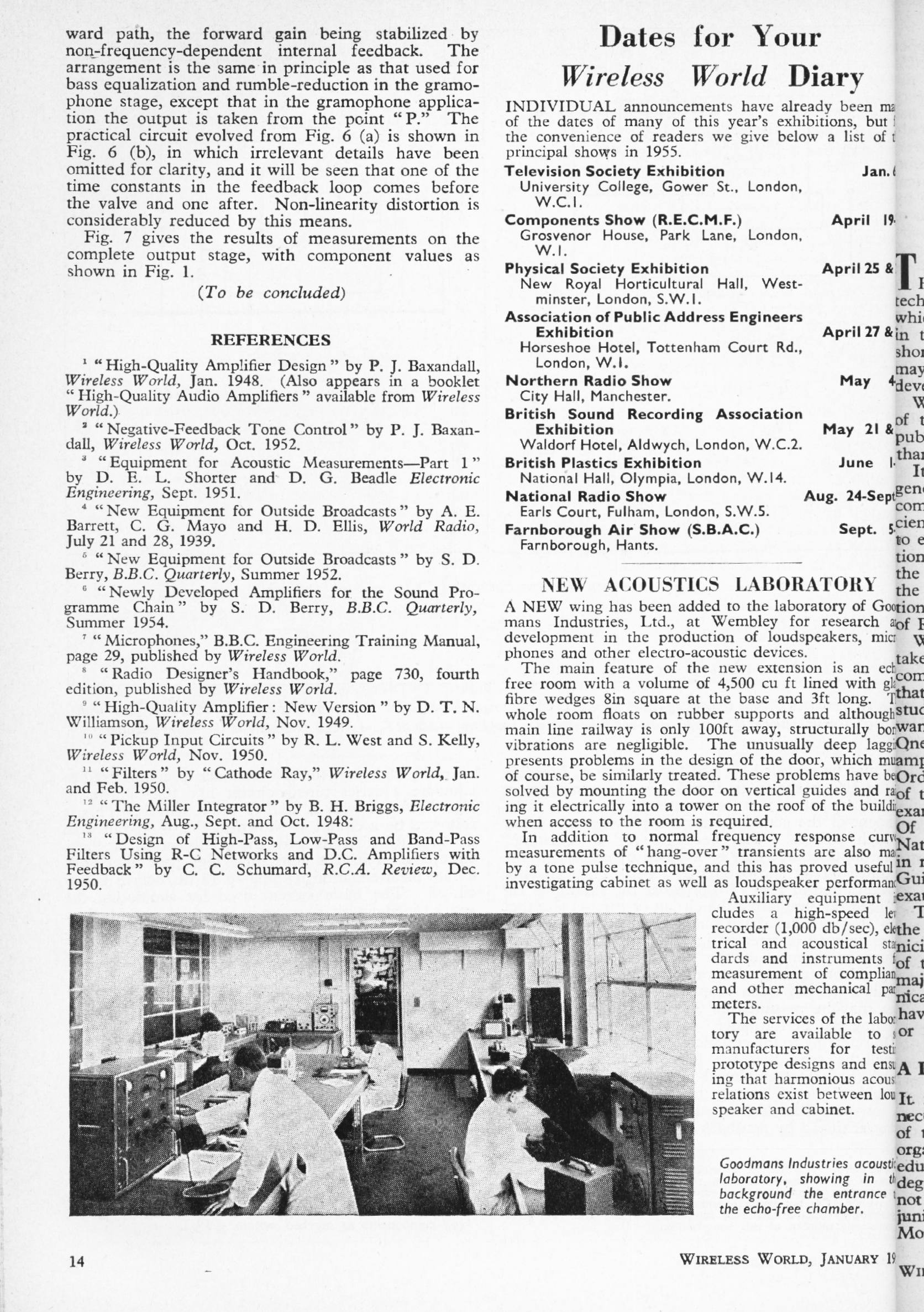
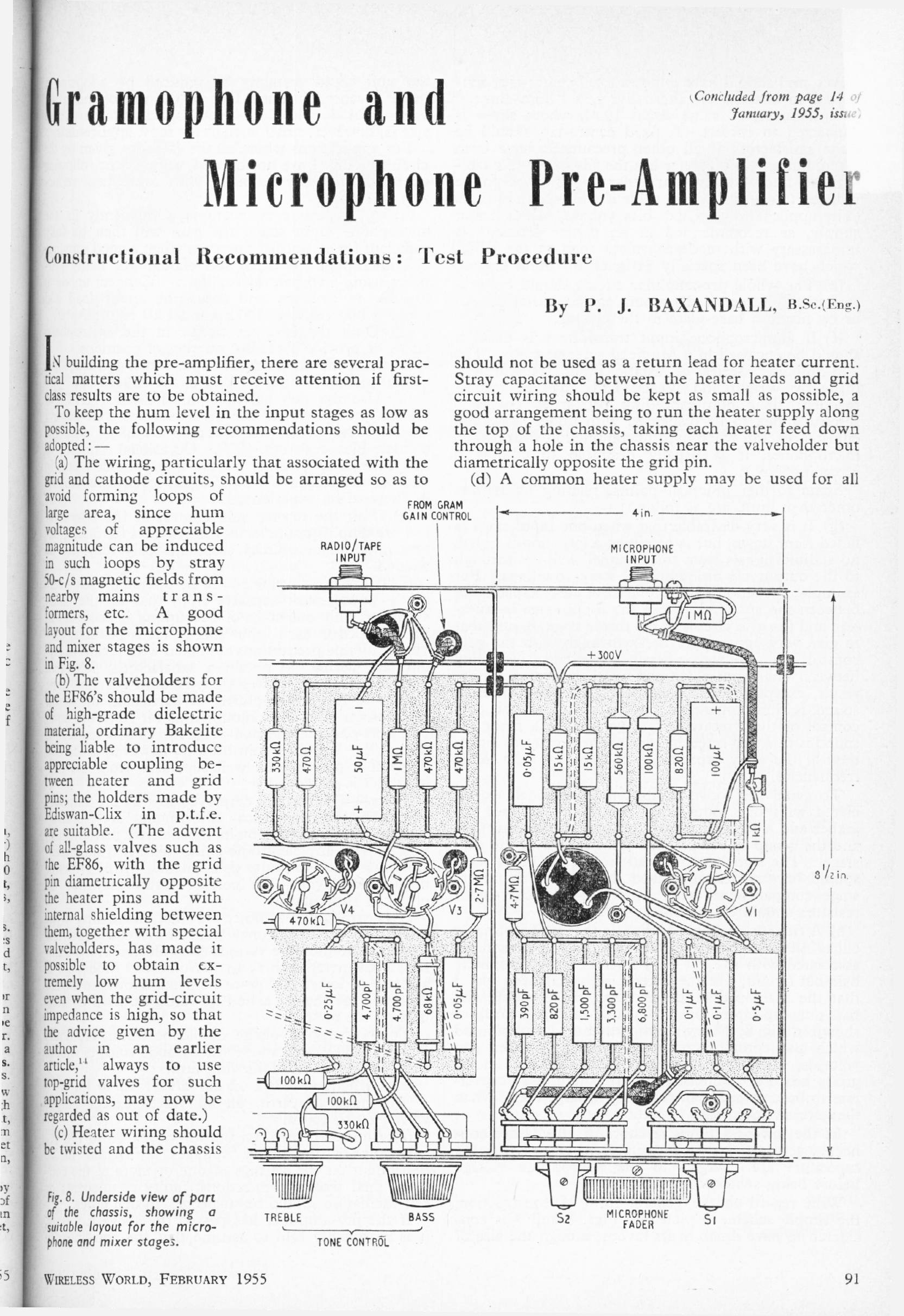
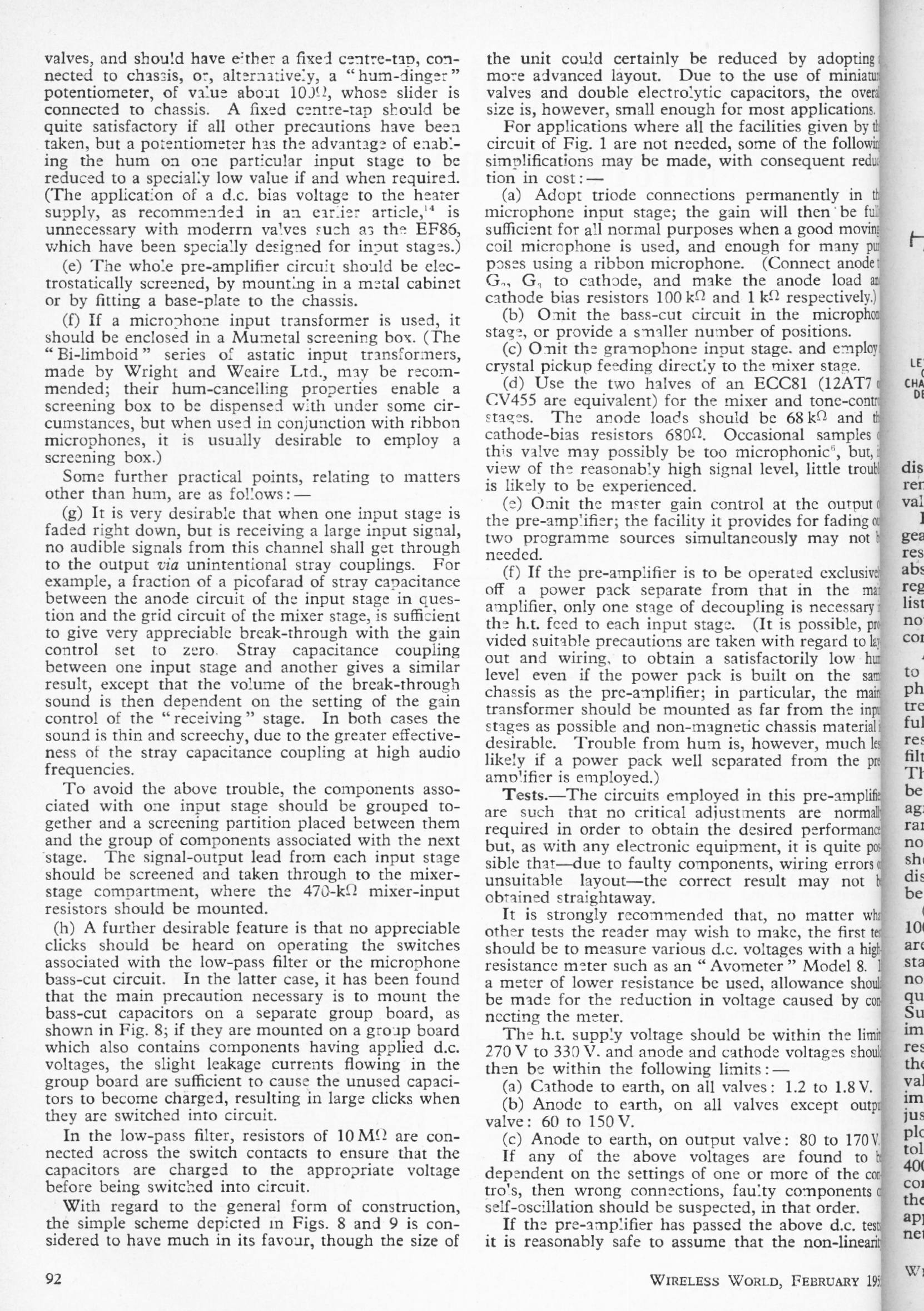
GRAMOPHONE & MICROPHONE PRE-AMPLIFIER: January, February 1955
Peter Baxandall
A fairly complex design, using five valves. This is the preamplifier referred to in the "Inexpensive High-Quality Amplifier" article of March 1957.
I'm afraid the scanning is not wholly satisfactory as the volume has been bound so the extreme right text is not visible on every other page.
|
|
|
|
|
|
| ||||||||
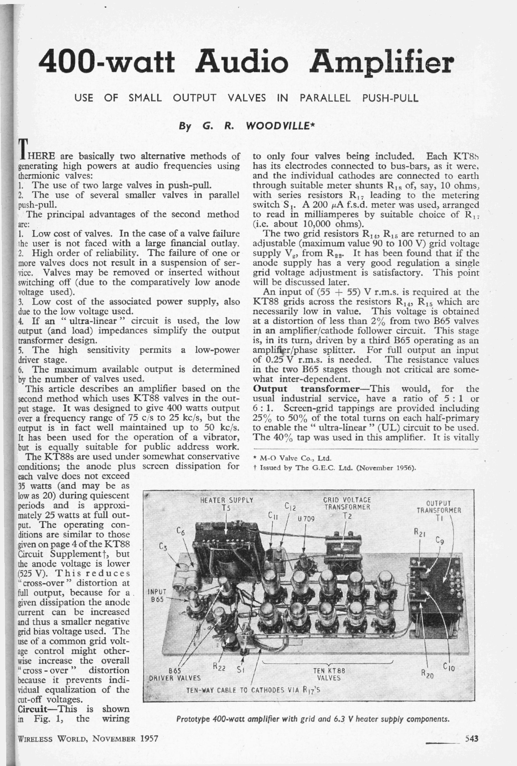
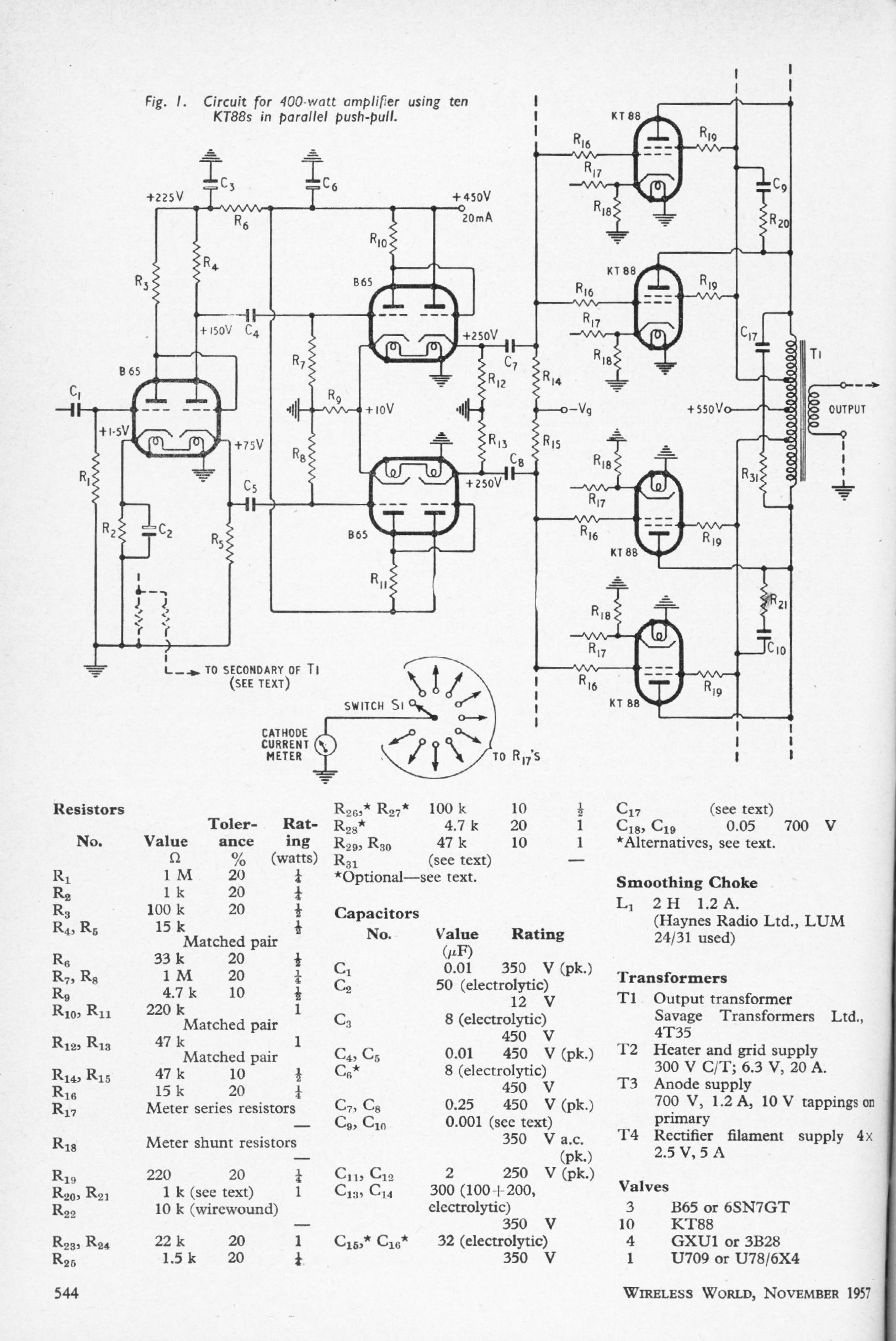
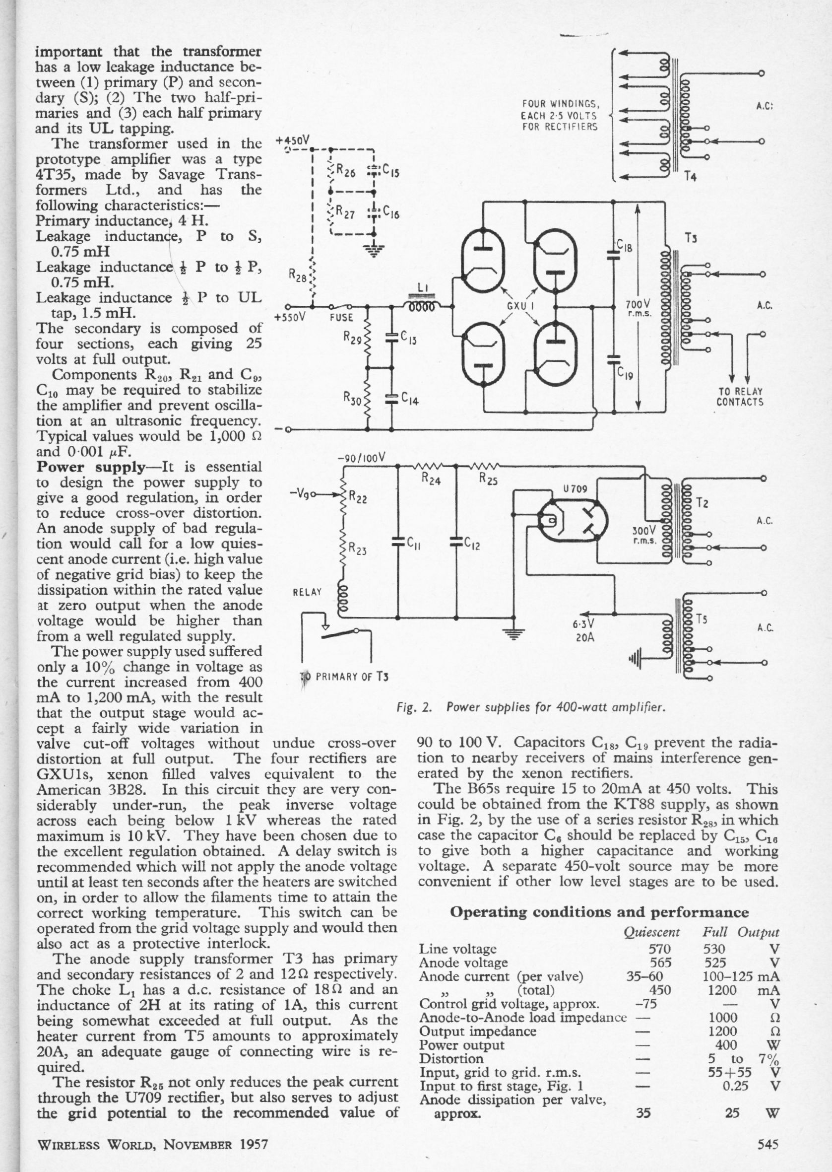
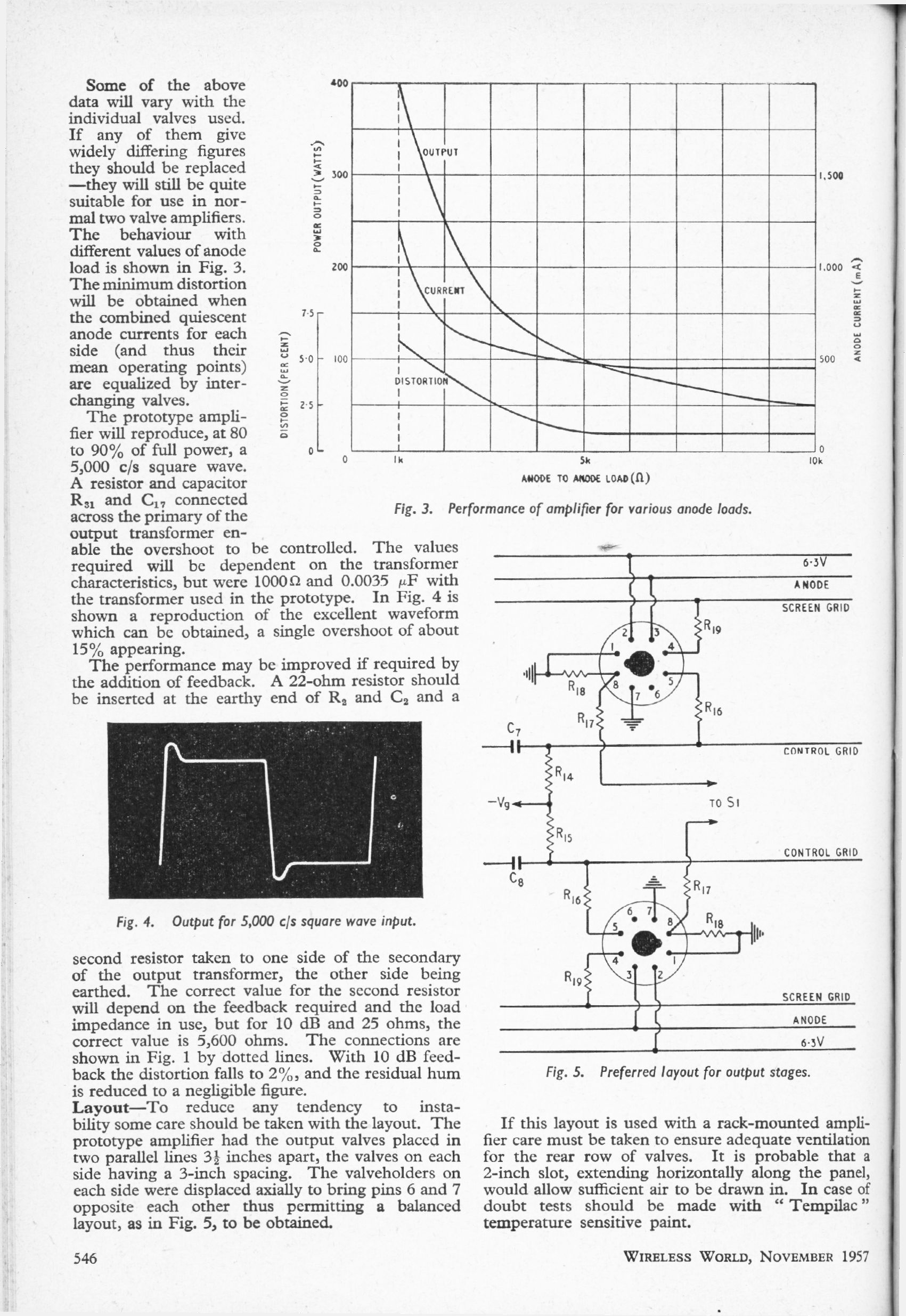
400W POWER AMPLIFIER: Nov 1955
G R Woodville
A seriously powerful amplifier by valve standards, with ten KT88s in parallel push-pull.
|
| ||||||
The circuit consists of a voltage-gain stage and a phase splitter (one double-triode), a pair of voltage-gain stages, and a pair of cathode-followers to drive the array of output valves. These have their screen grids driven from a tap on the output transformer, so I suppose this is an "ultra-linear" topology. The KT88 is a beam tetrode/kinkless tetrode, hence the "KT". | |||||||
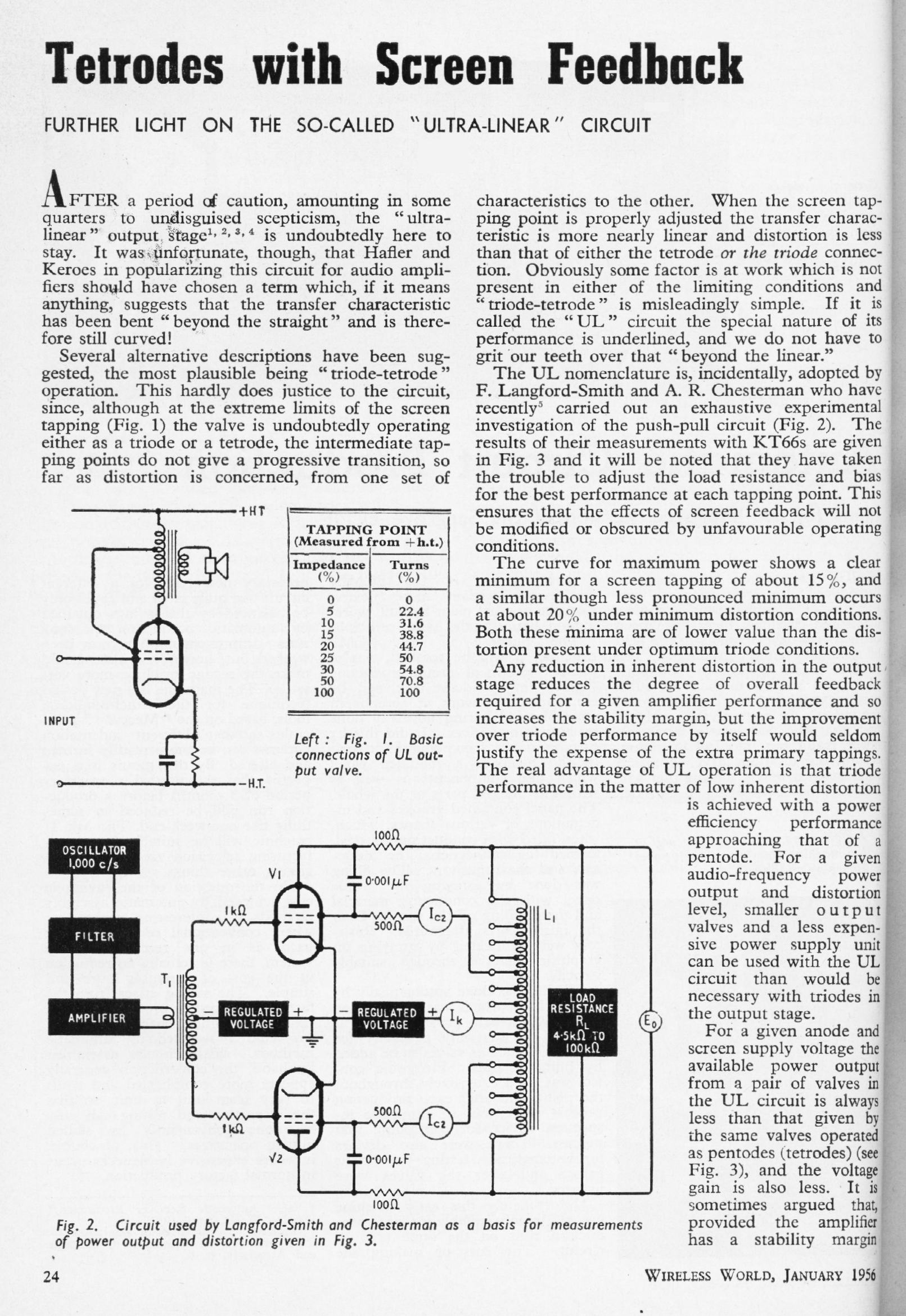
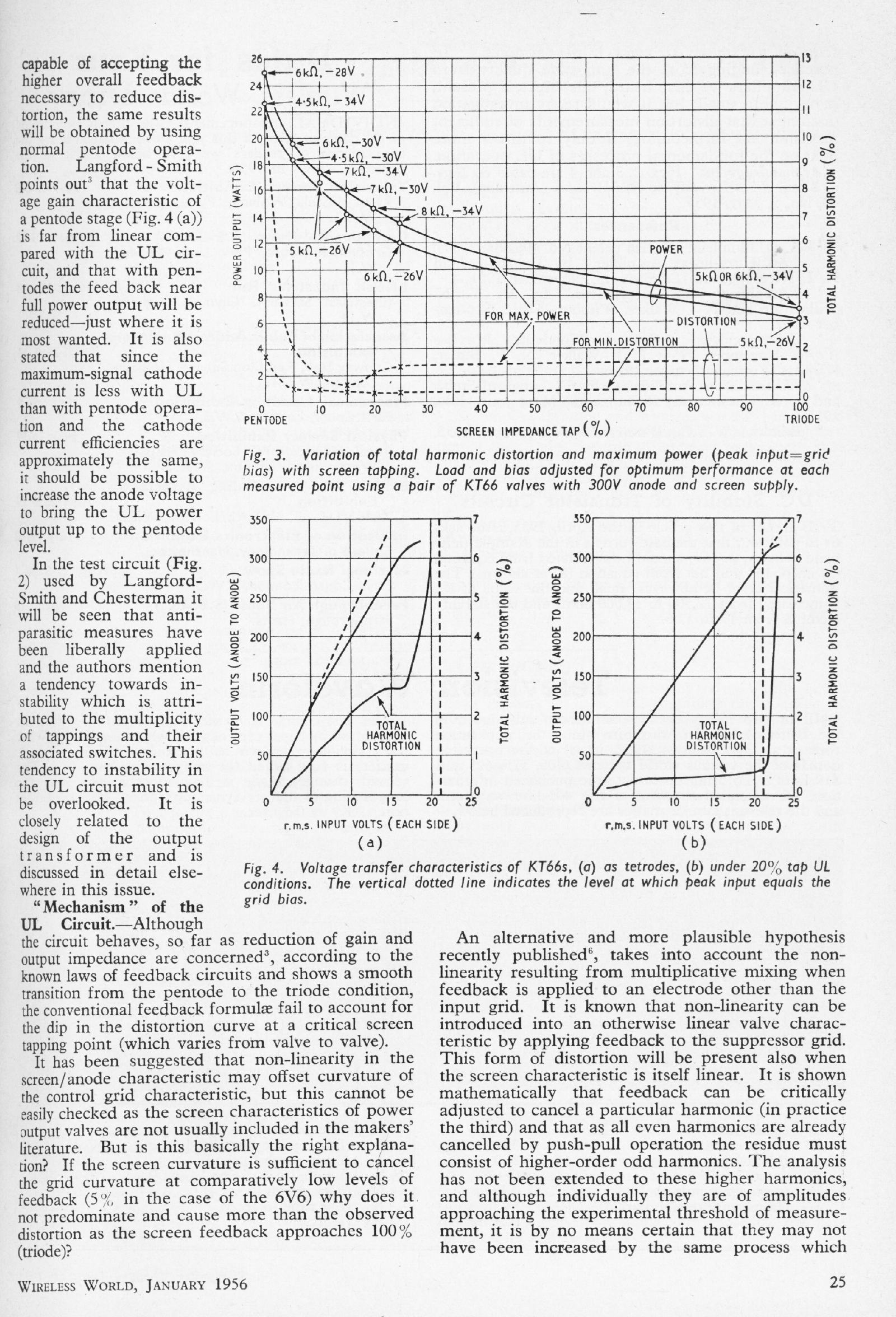
TETRODES WITH SCREEN FEEDBACK: Jan 1956
Author unknown (WW staff?)
A review of the so-called Ultra-Linear output stage for valve amplifiers. It was controversial when first introduced.
|
|
ULTRA-LINEAR OUTPUT TRANFORMERS: Jan 1956
D M Leakey & R M Gilson
An article focusing on possible stability problems in ultra-linear output stage valve amplifiers.
|
|
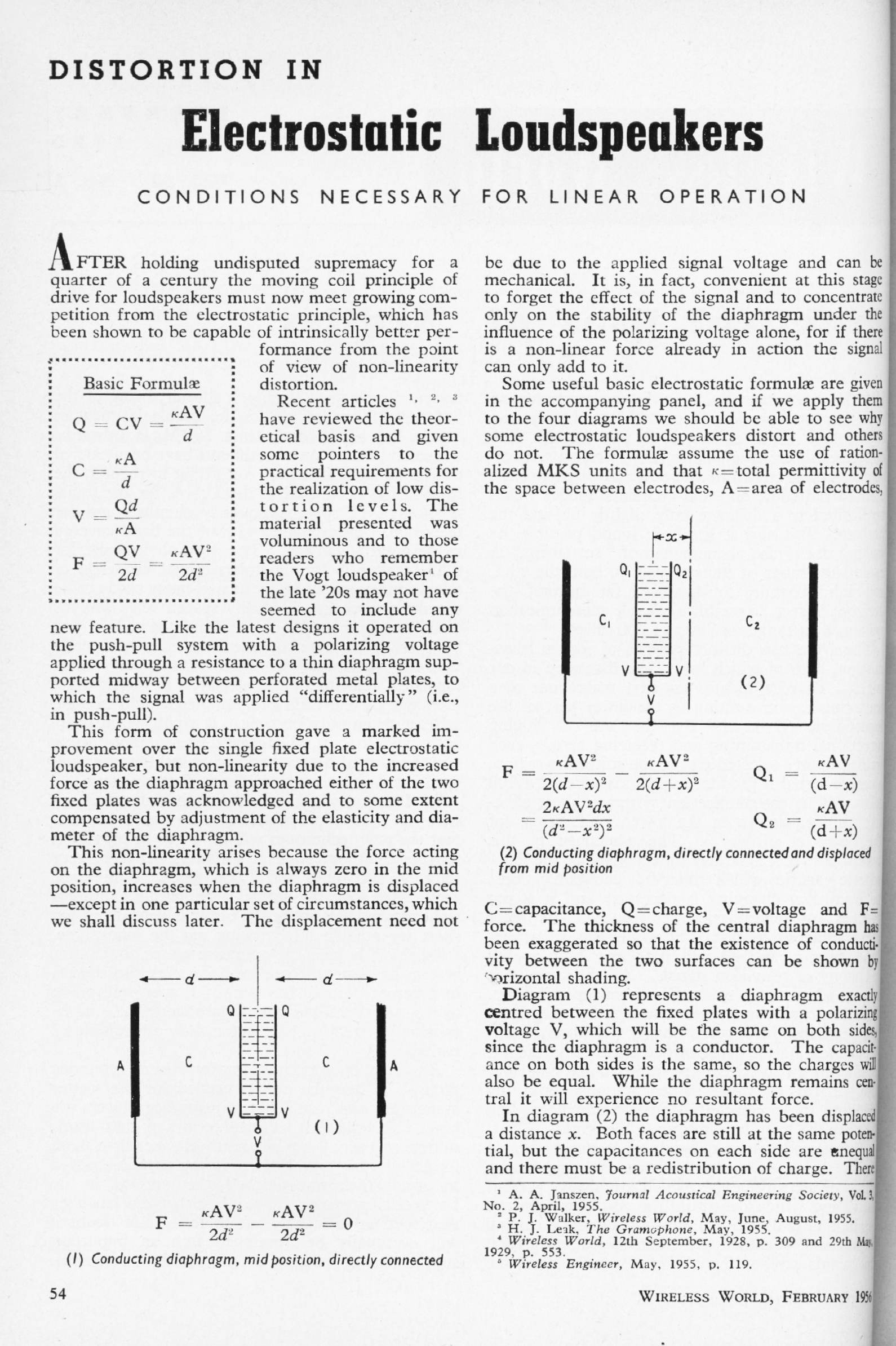
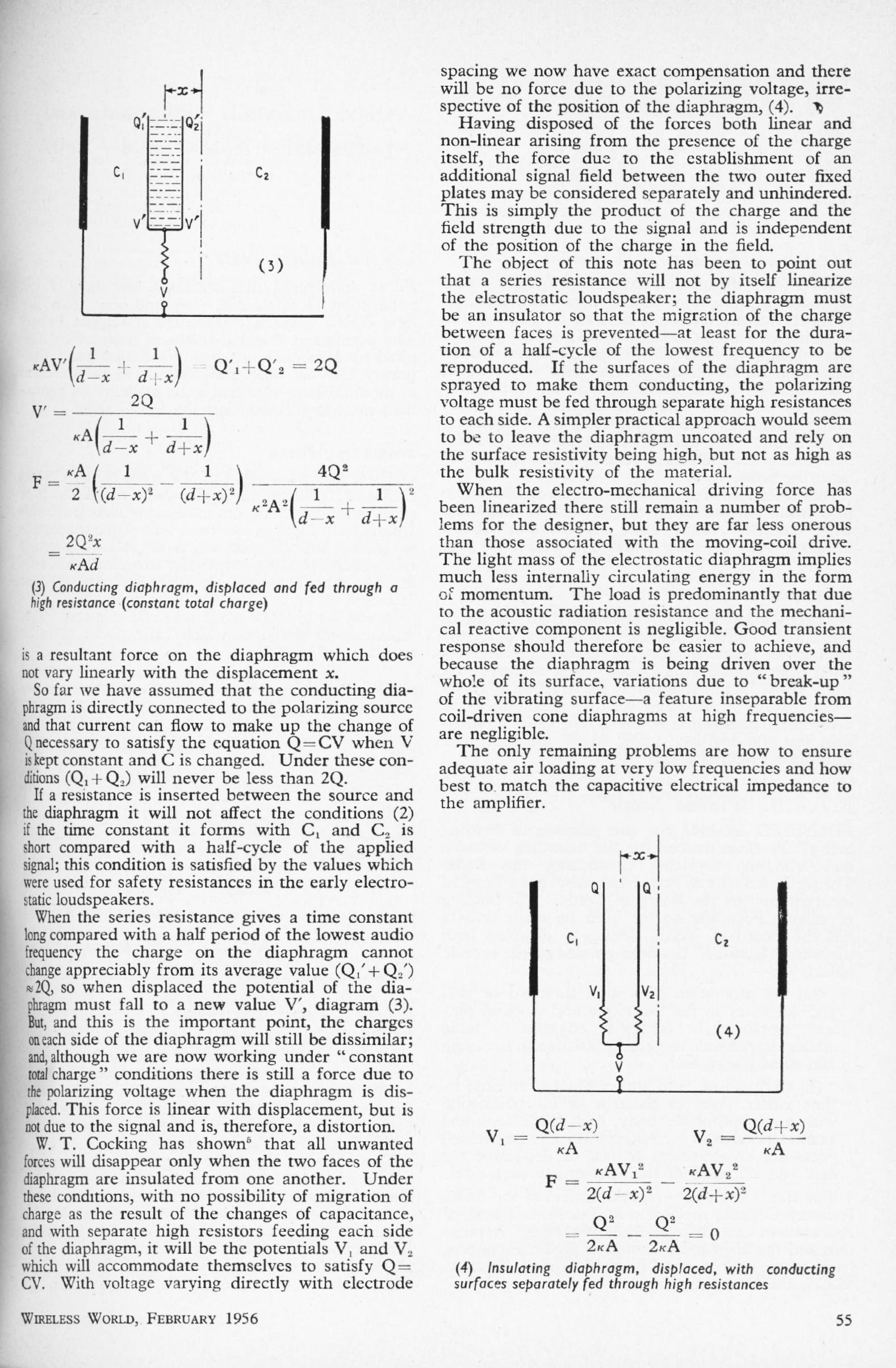
DISTORTION IN ELECTROSTATIC LOUDSPEAKERS: Feb 1956
Author unknown (WW staff?)
A short note on the non-linearity and stability of electrostatic speaker diaphragms, pointing out that some sort of resistive rather than metallic coating is required, to prevent charge migration.
|
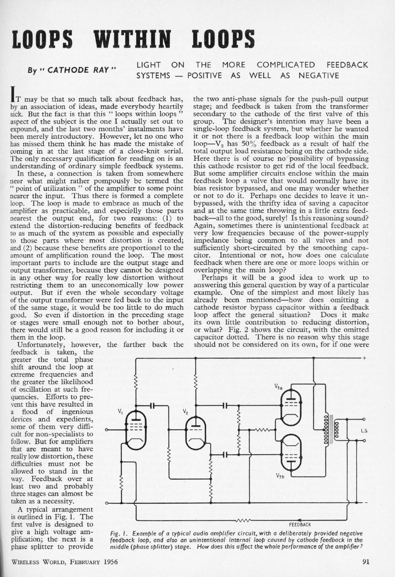
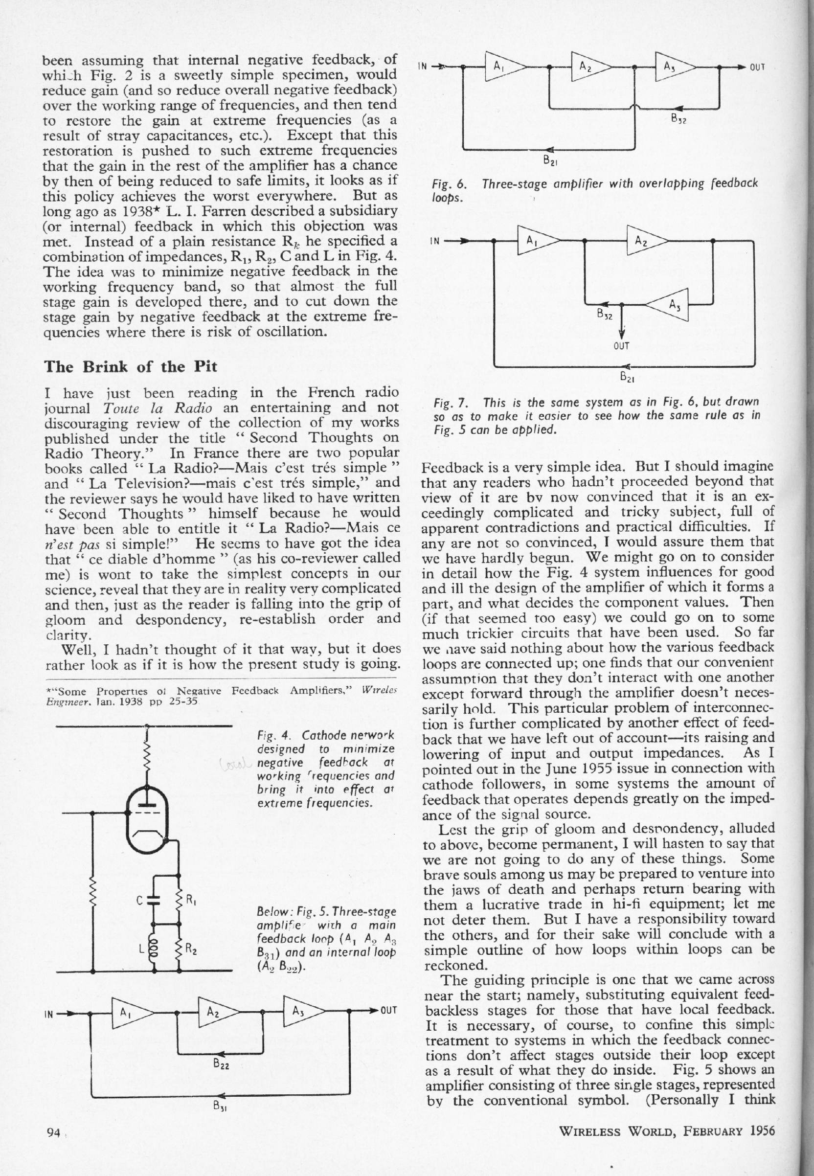
LOOPS WITHIN LOOPS: Feb 1956
'Cathode Ray'
'Cathode Ray' was the pseudonym of M G Scroggie. (1901 - 1989) He contributed more than 800 articles to Wireless World. One might have expected him to be joined by Anode Arnold and Sid The Grid, but mercifully this never actually happened.
|
|
| This article on negative feedback deals with nested loops, and the use of positive feedback within the main loop. A clear understanding of feedback was more important in valve days, because the distortion of the output transformer, especially at LF, required that the global negative feedback loop be closed around it by taking the return path from the secondary. However the phase-shifts in the transformer made it difficult to apply more than a very modest amount NFB (compared with solid-state amplifiers) without instability occurring. | ||||||
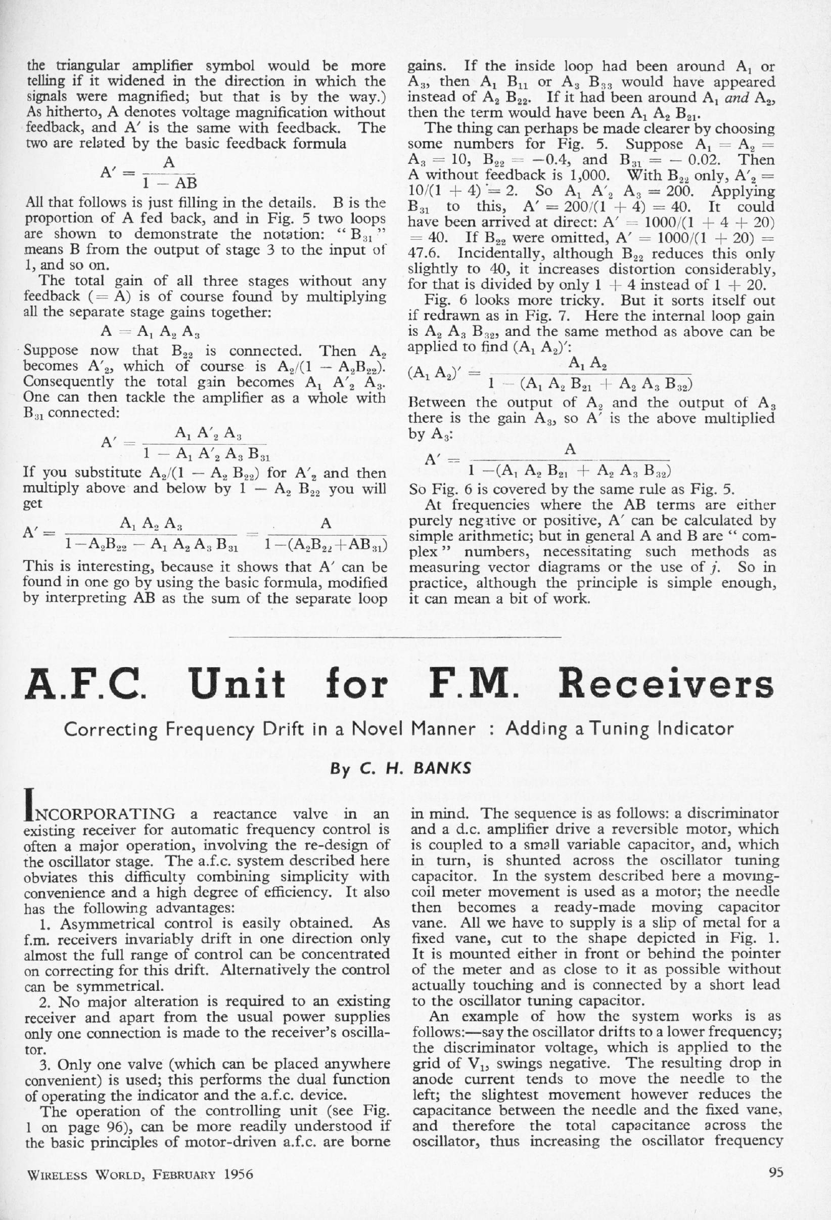
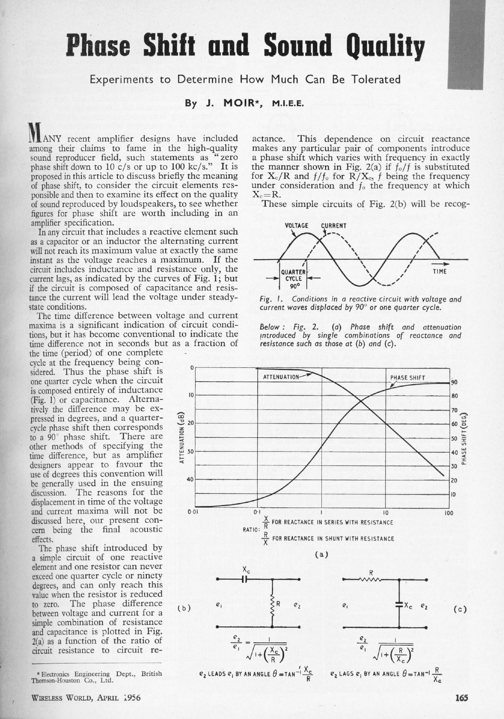
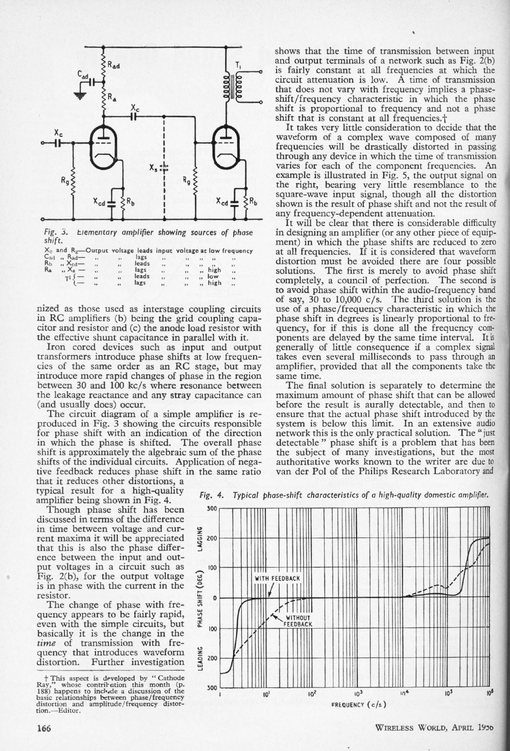
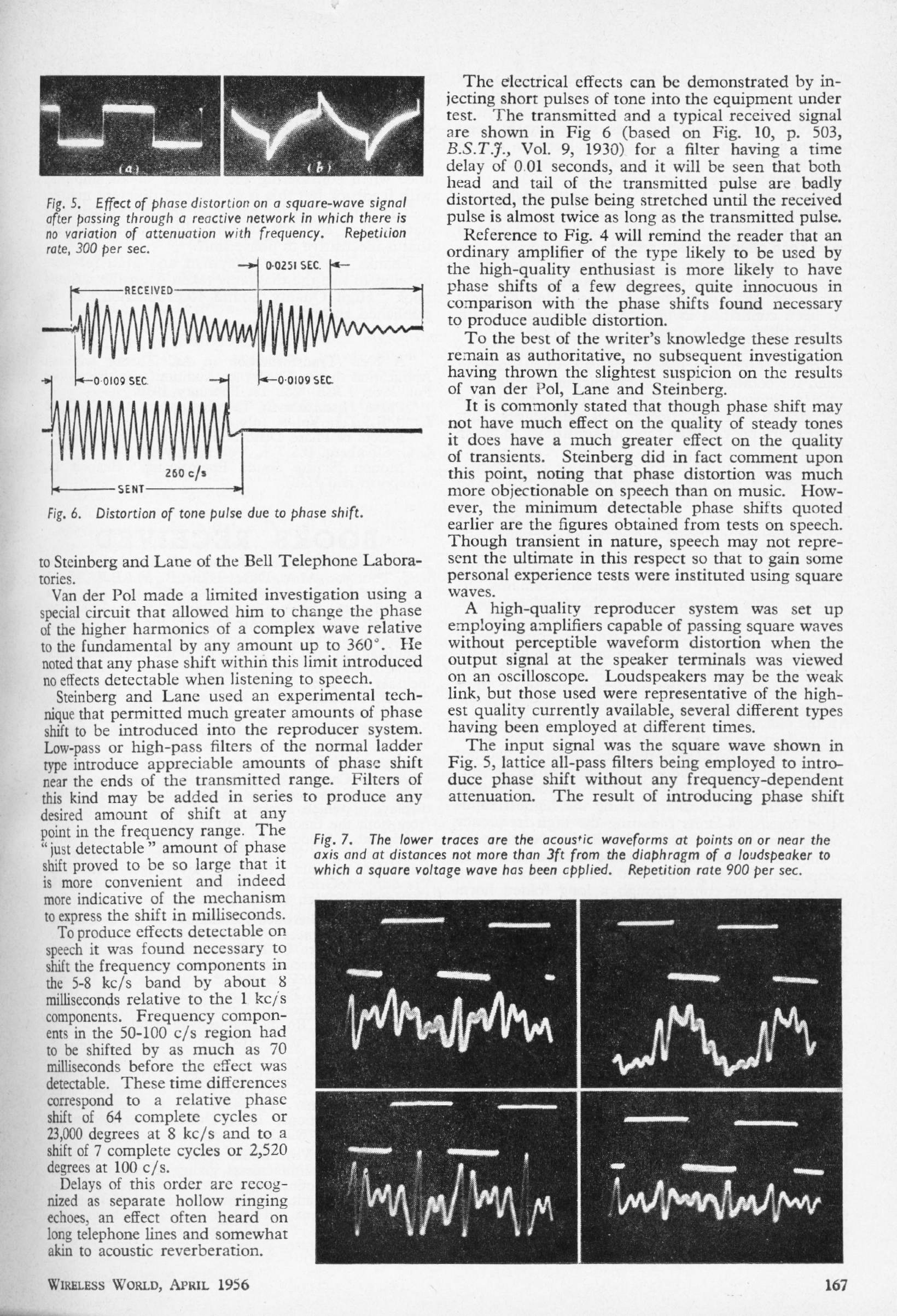
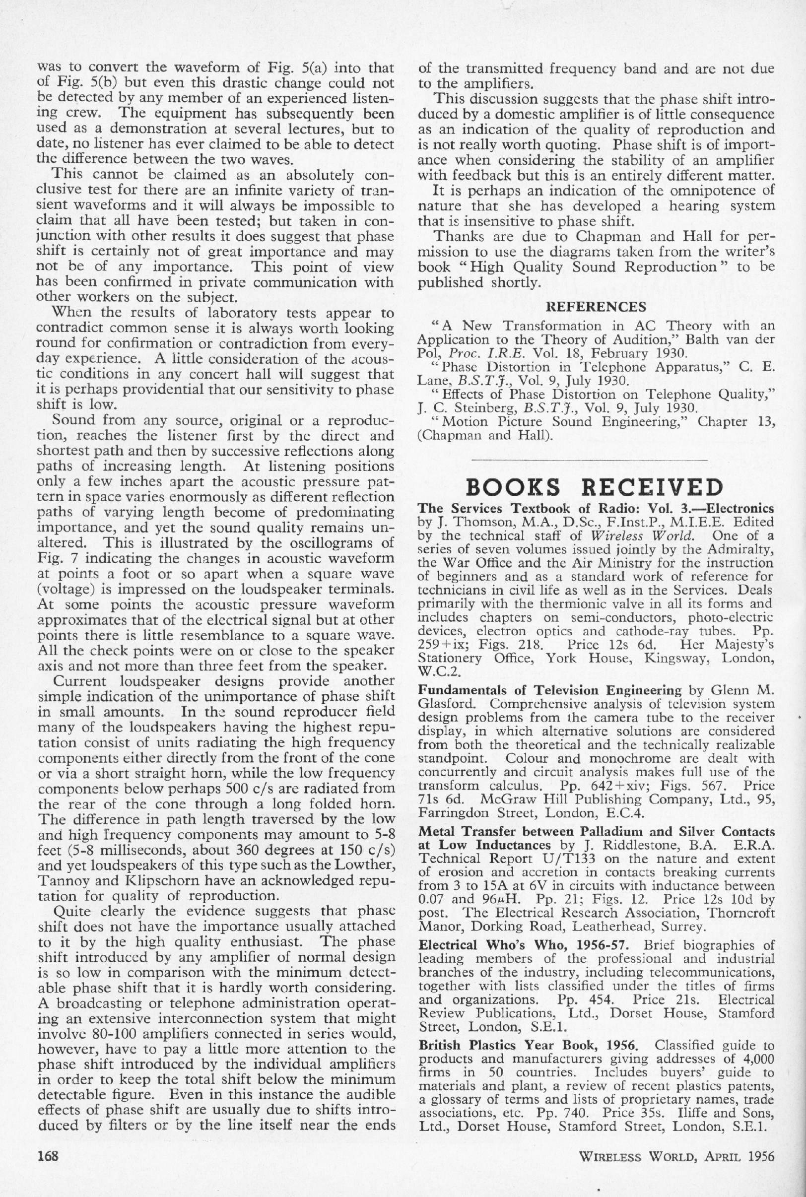
PHASE SHIFT AND SOUND QUALITY: Apr 1956
James Moir
A careful examination of the audibility of phase shift by the well-respected James Moir. He concludes that the amount of phase-shift you are likely to get in an amplifier- and he was of course talking about valve amplifiers with output transformers- is completely inaudible. More modern studies confirm this, and the article is as valid today as when it was written.
|
|
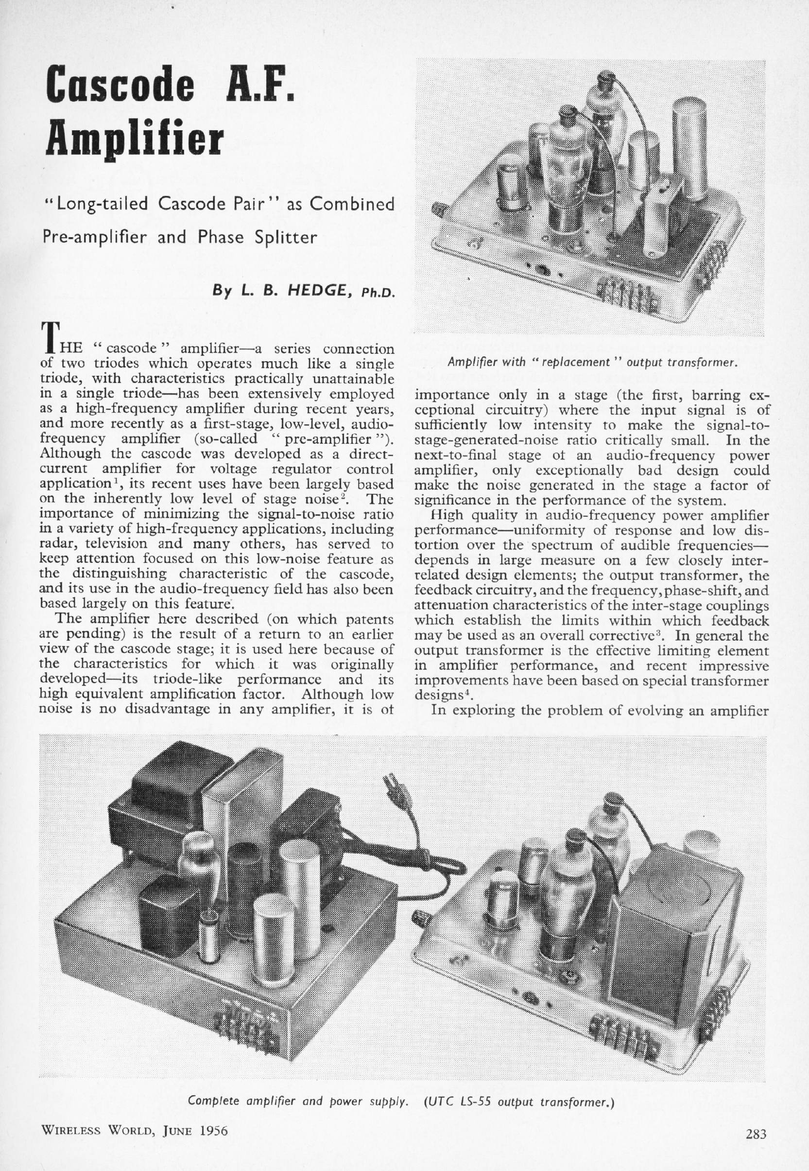
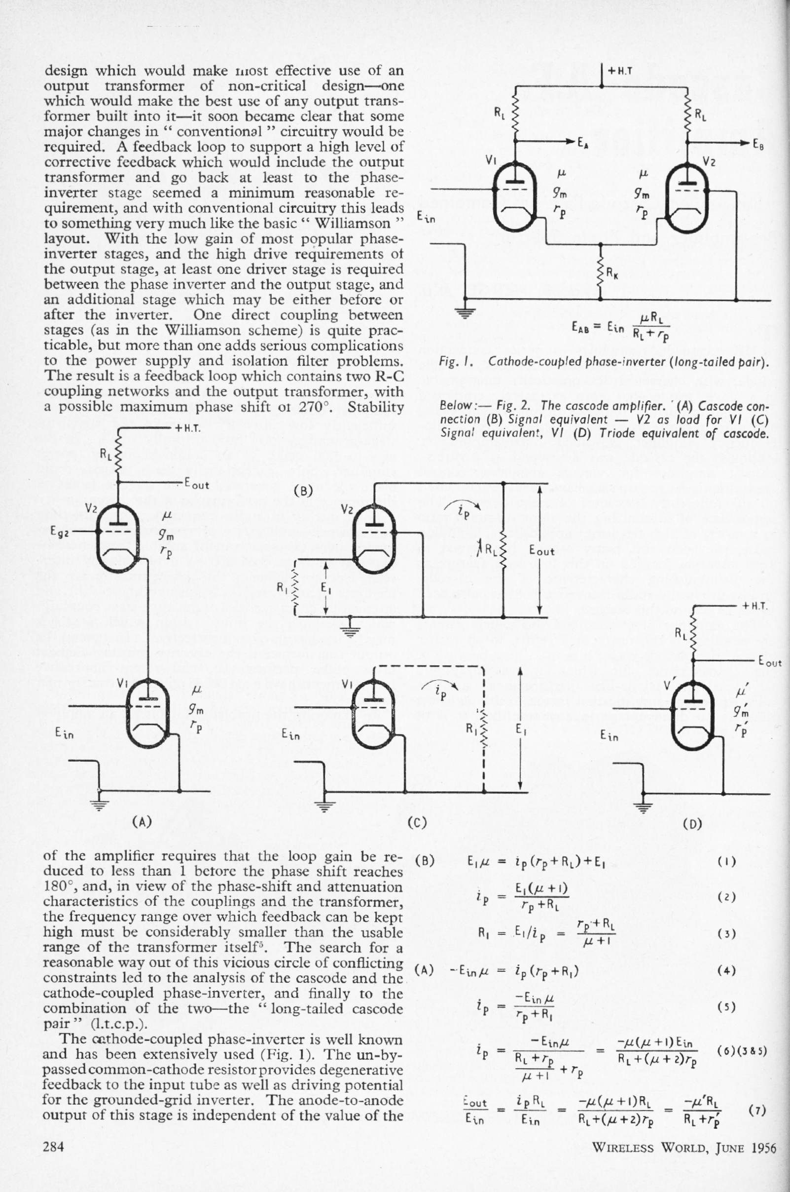
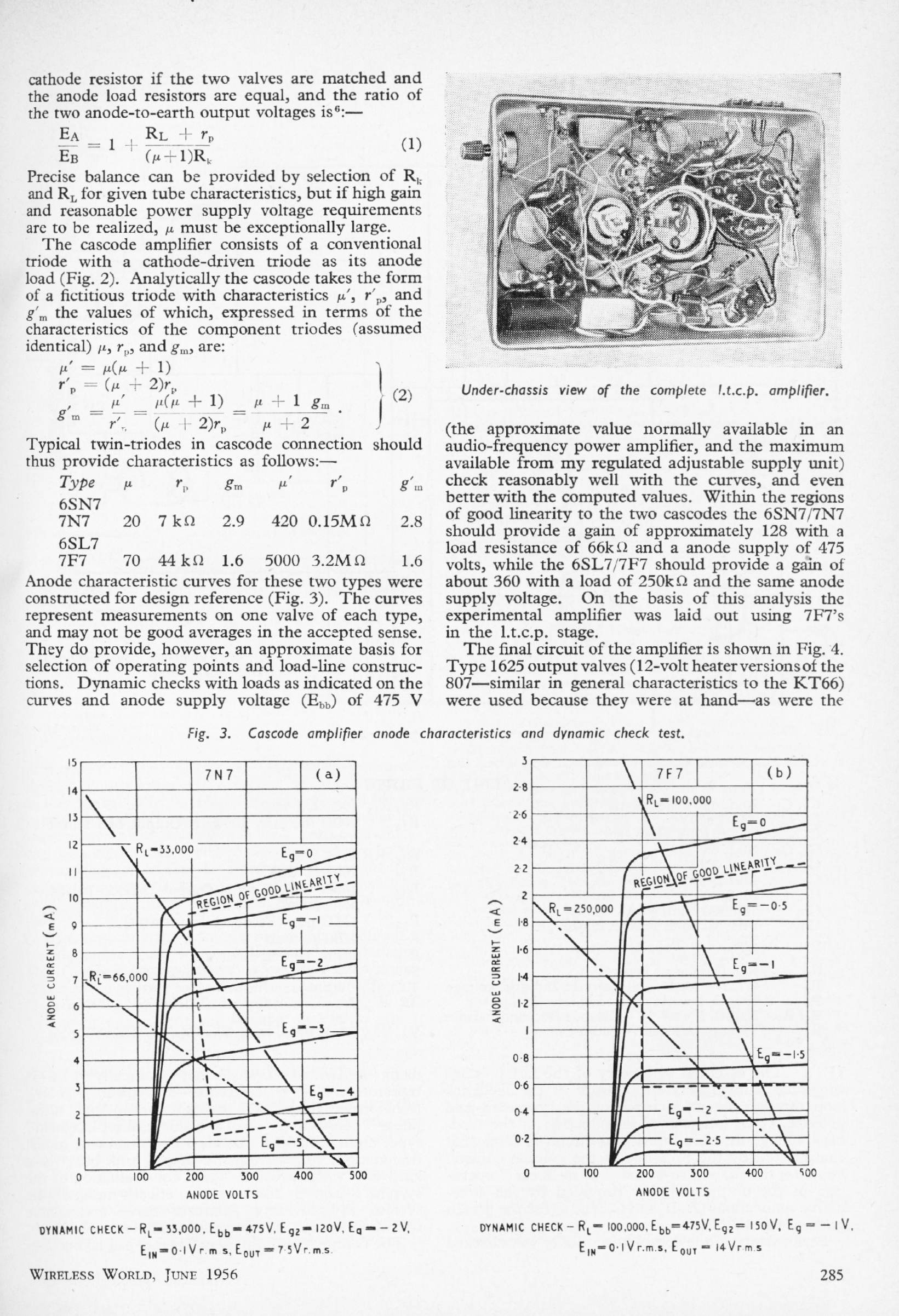
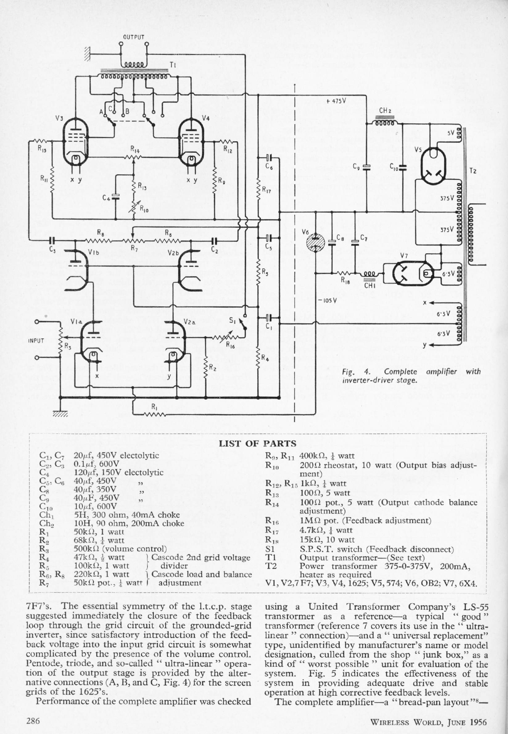
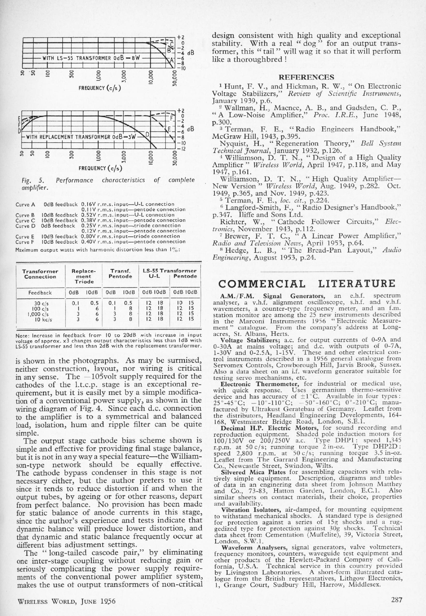
CASCODE AF AMPLIFIER: June 1956
L B Hedge
A cascode valve amplifier using a "long-tailed cascode pair" as combined preamplifier and phase-splitter. Apparently a patent was applied for, but the idea does not seem to have prospered.
|
|
|
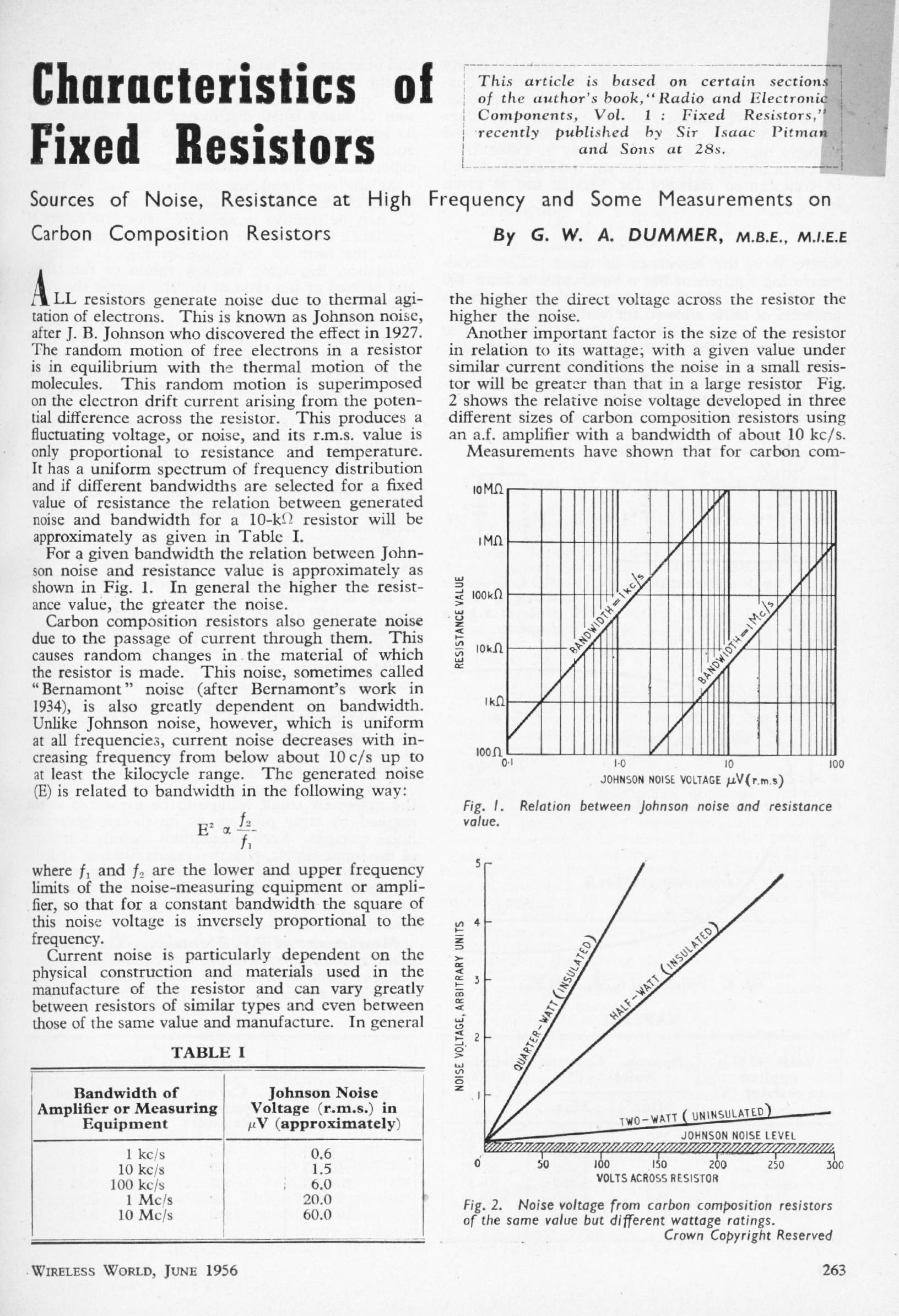
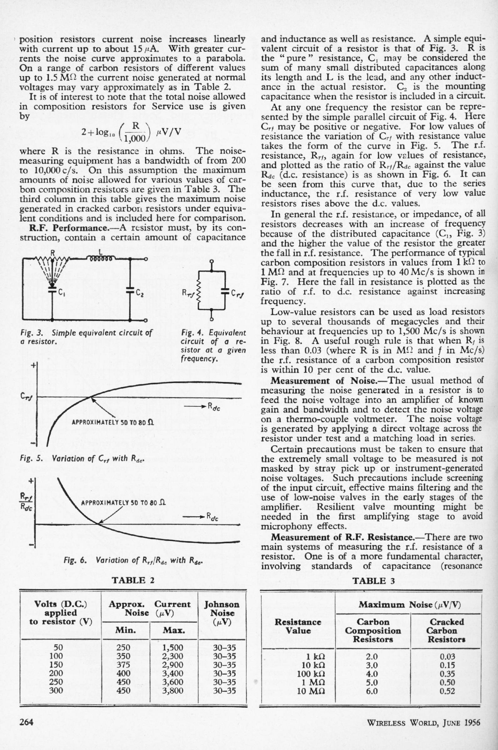
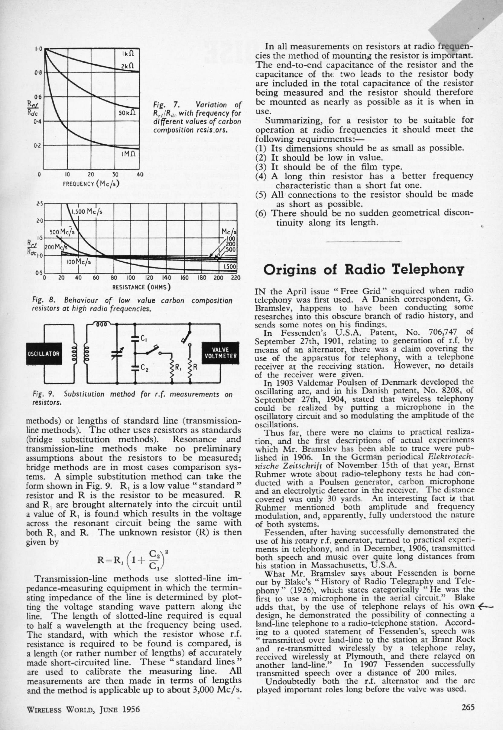
CHARACTERISTICS OF FIXED RESISTORS: June 1956
G W A Dummer
This article is a collection of information on carbon-composition resistors. Since their use nowadays is confined to a few specialist niches, data is hard to come by. What we have here could be useful.
|
|
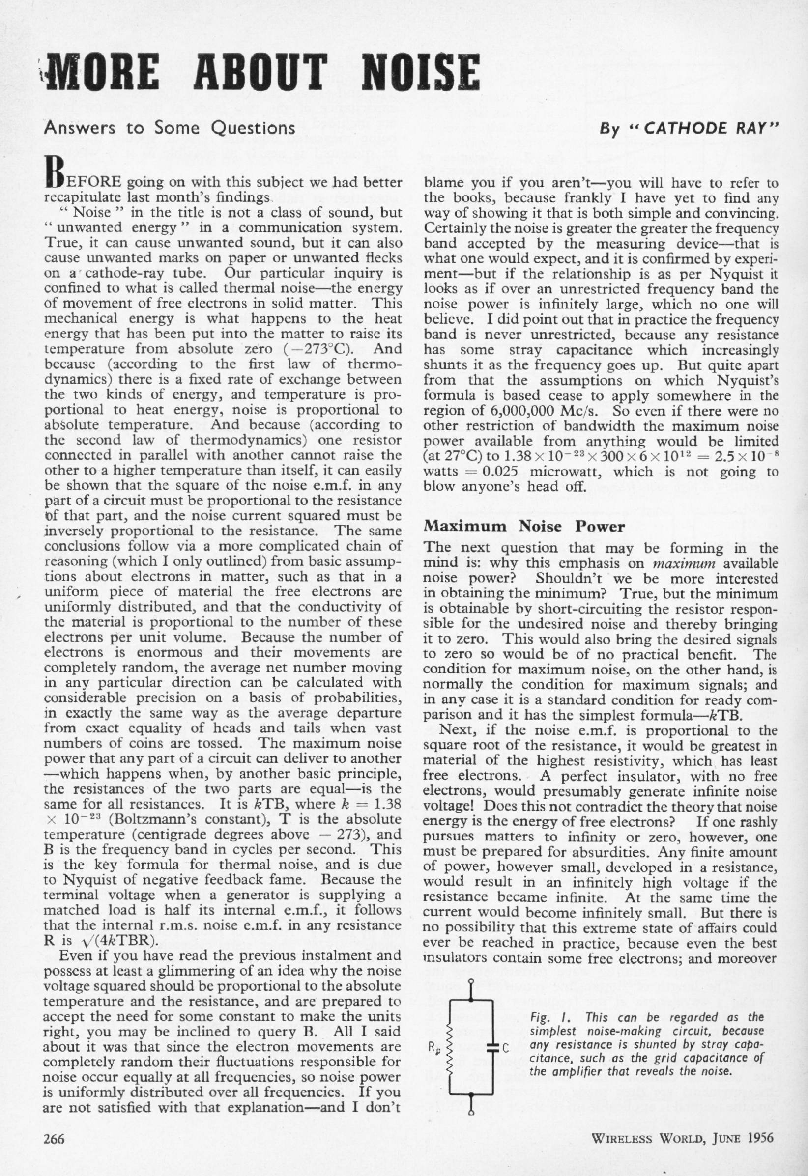
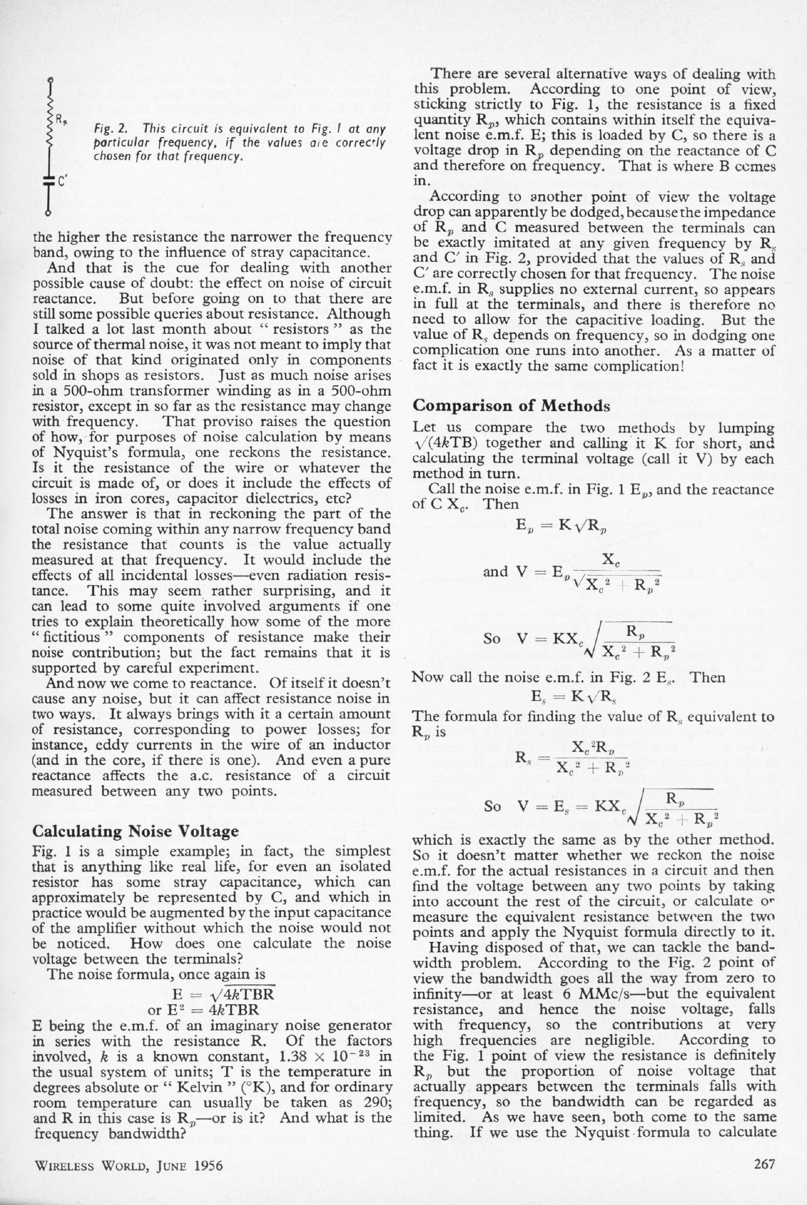
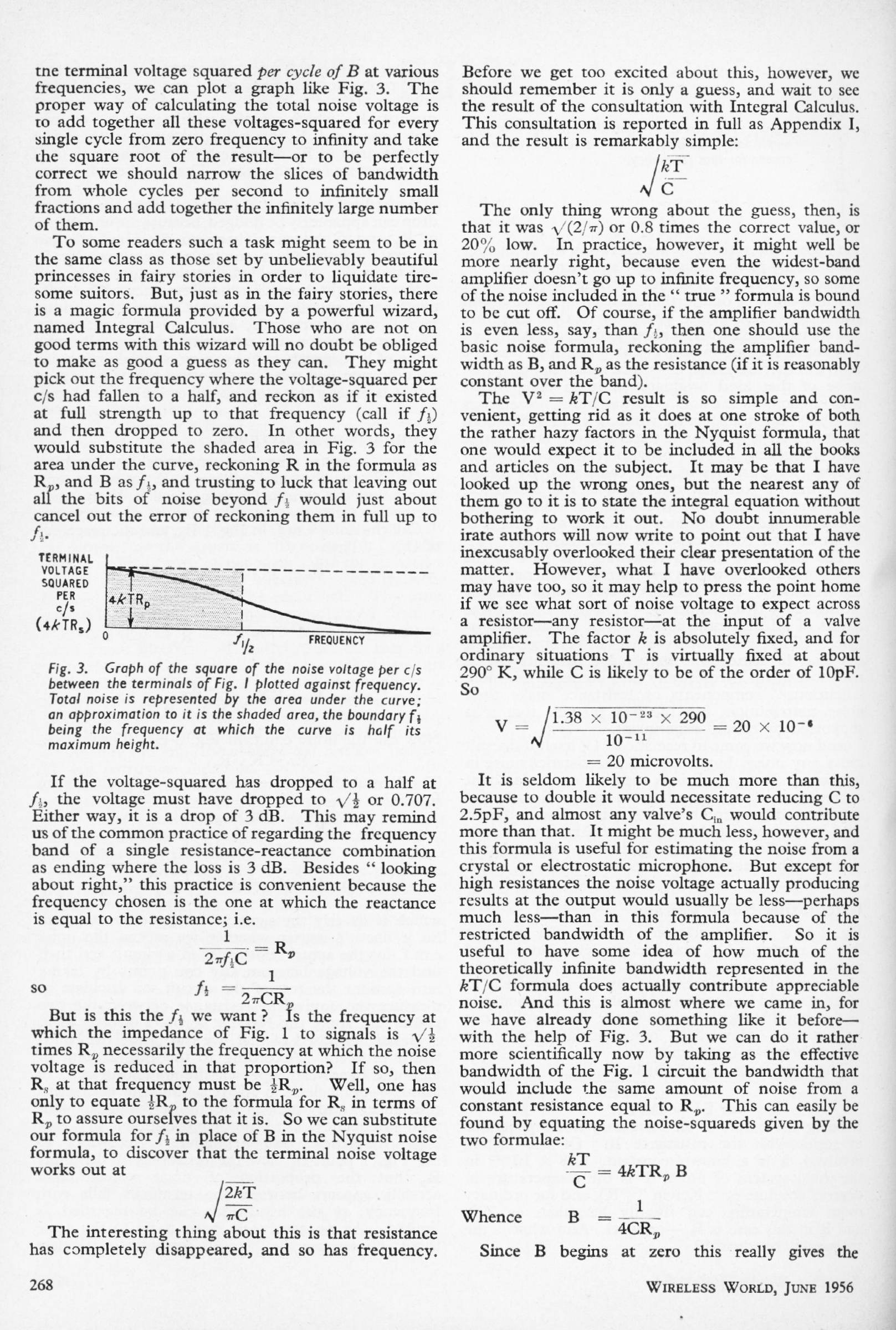
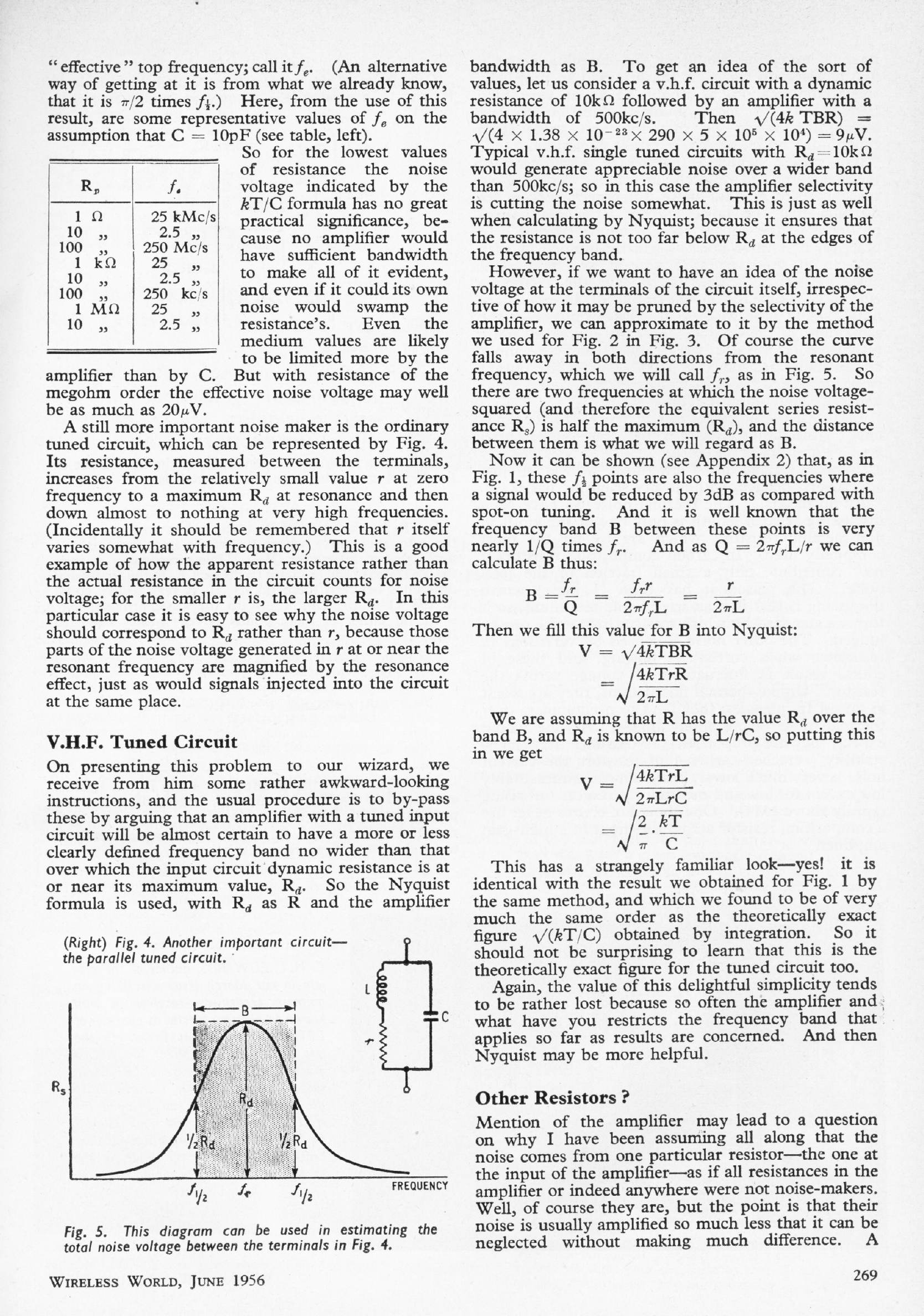
MORE ABOUT NOISE: June 1956
'Cathode ray'
An interesting examination of some complications affecting the calculation of Johnson noise in resistors.
|
|
|
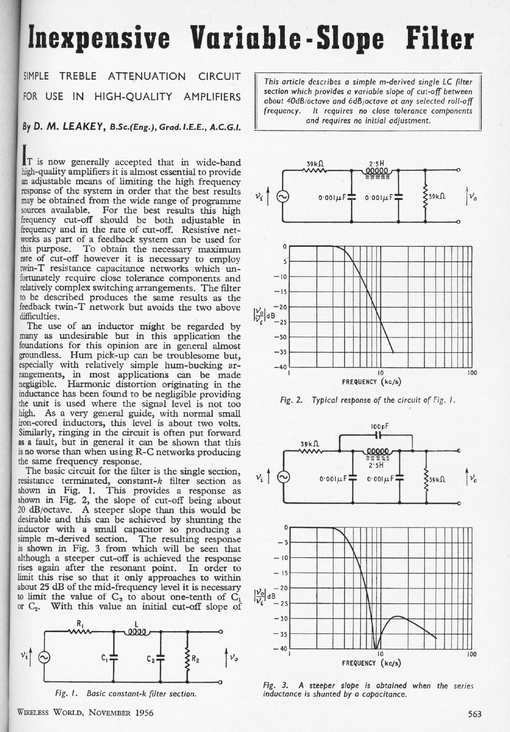
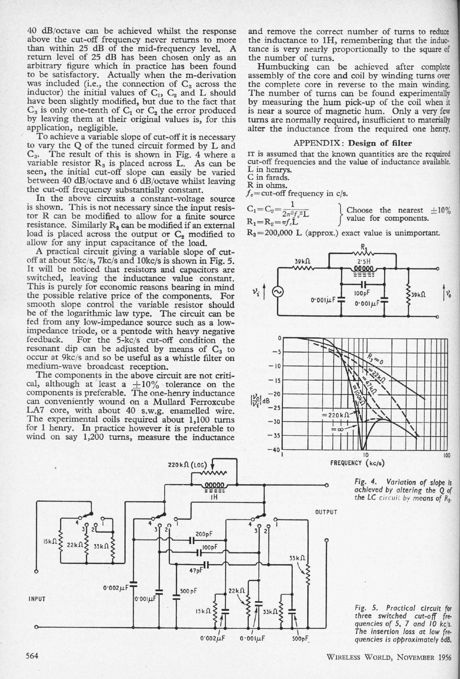
INEXPENSIVE VARIABLE SLOPE FILTER: Nov 1956
D M Leakey
| In the days of vinyl discs, only the most basic of preamplifiers would have been without some sort of HF filter to dull the effect of surface noise and distortion. This is a comprehensive design giving a wide choice of lowpass filter characteristics, including a rather severe setting that is 3 dB down just above 4 kHz, with a deep notch at 9 kHz.The passive filter is implemented with a 1 Henry inductor that is constructed by winding 1200 turns of fine enamelled wire on a Ferroxcube core. (We made our own entertainment in those days!) I think the winding process would make me lose the will to live. You can see why active filters are preferred now. |
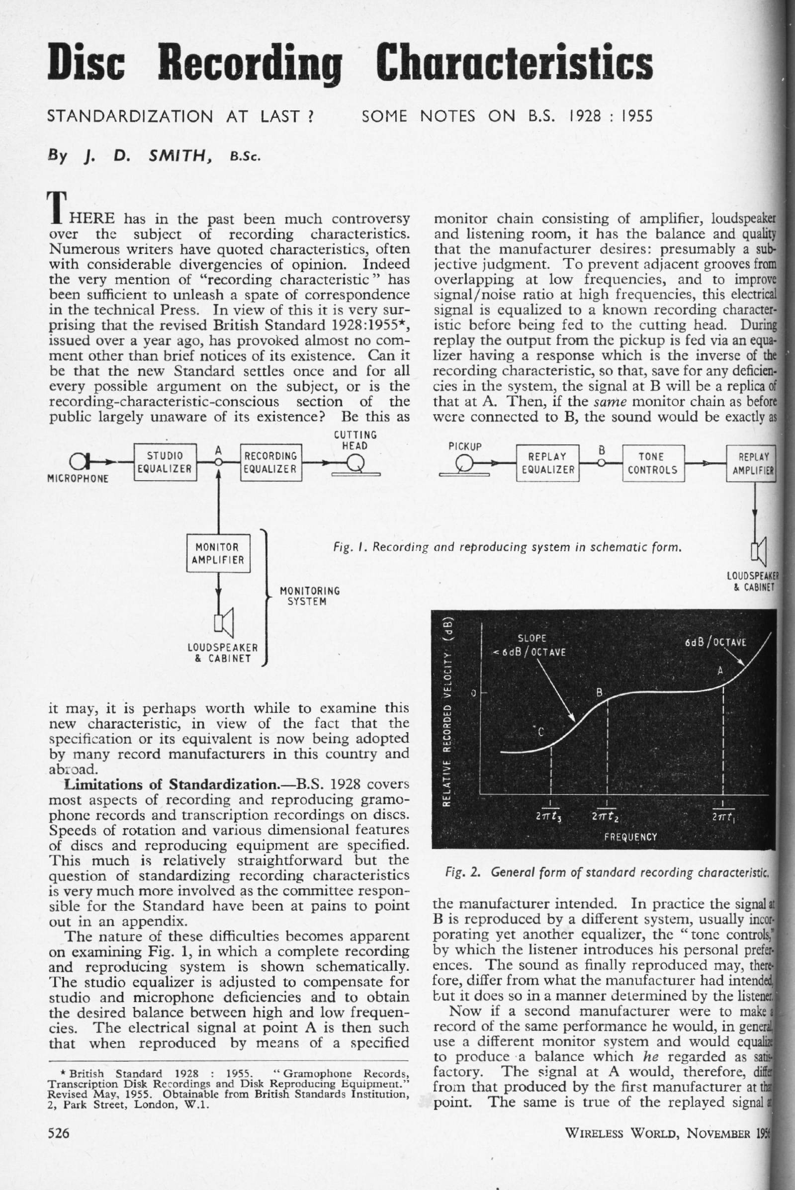
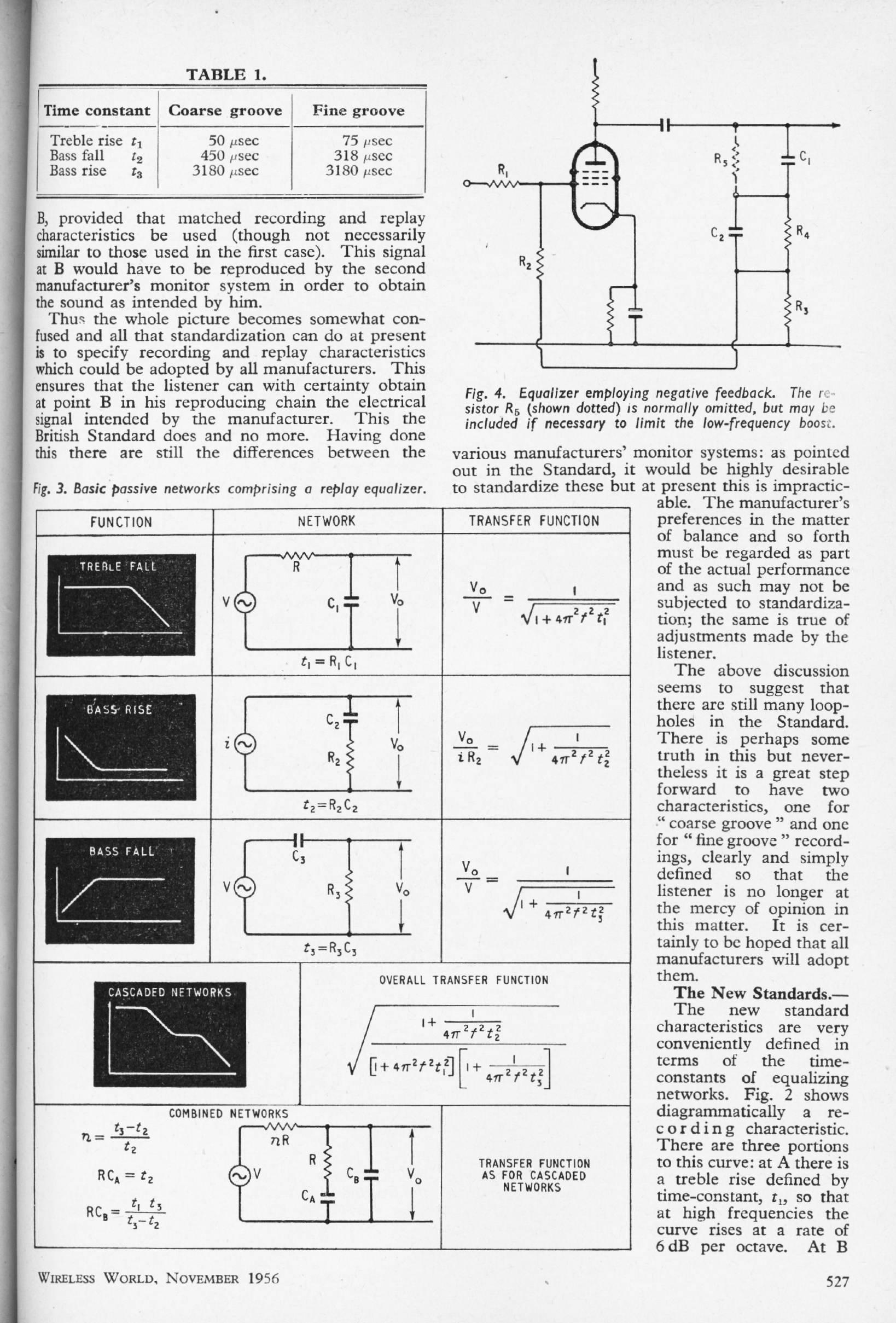
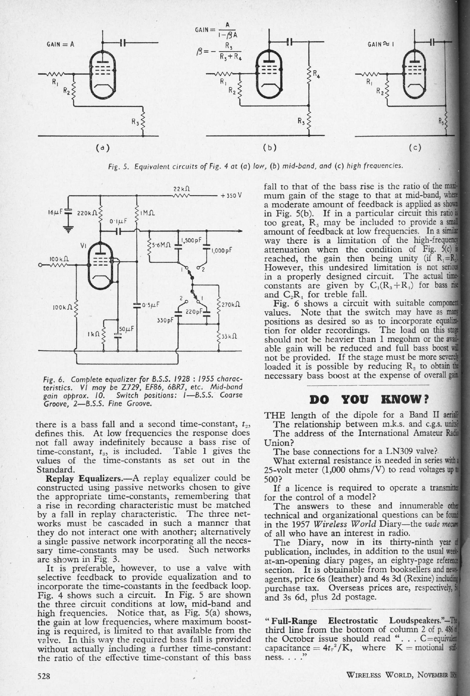
DISC RECORDING CHARACTERISTICS: Nov 1956
J D Smith
Up to 1955 a great variety of equalisation curves for disc cutting and replay were in use. It was common for a preamplifier to have four or more switchable equalisation options for disc replay, selected according to the company who had made the record you were playing. In 1955 the USA standardised on what became known as RIAA equalisation, and the same standard was adopted in the UK as BS1928/1955. This came as a great relief to all concerned.
|
|
OUTPUT TRANSFORMERLESS AMPLIFIERS: Feb 1957
Author unknown (WW staff?)
A review of the tricky business of making valve amplifiers without output transformers. One of the most powerful motivations was that it would allow much more negative feedback to be applied, because there would be no phase-shift caused by an output transformer.
|
|
| Note that on the first page the author refers to "...almost impossibly high values of condenser..." when discussing direct capacitive coupling to a loudspeaker. In those high-voltage days 50 uF was a big capacitor, not least physically. (see WW May 1955, p224) | ||||||
INEXPENSIVE HIGH-QUALITY AMPLIFIER: March, April 1957
Peter Baxandall
A 5W Class-A valve amplifier, published in two parts. Written with Peter's usual clarity of style.
|
|
|
|
|
|
| ||||||||
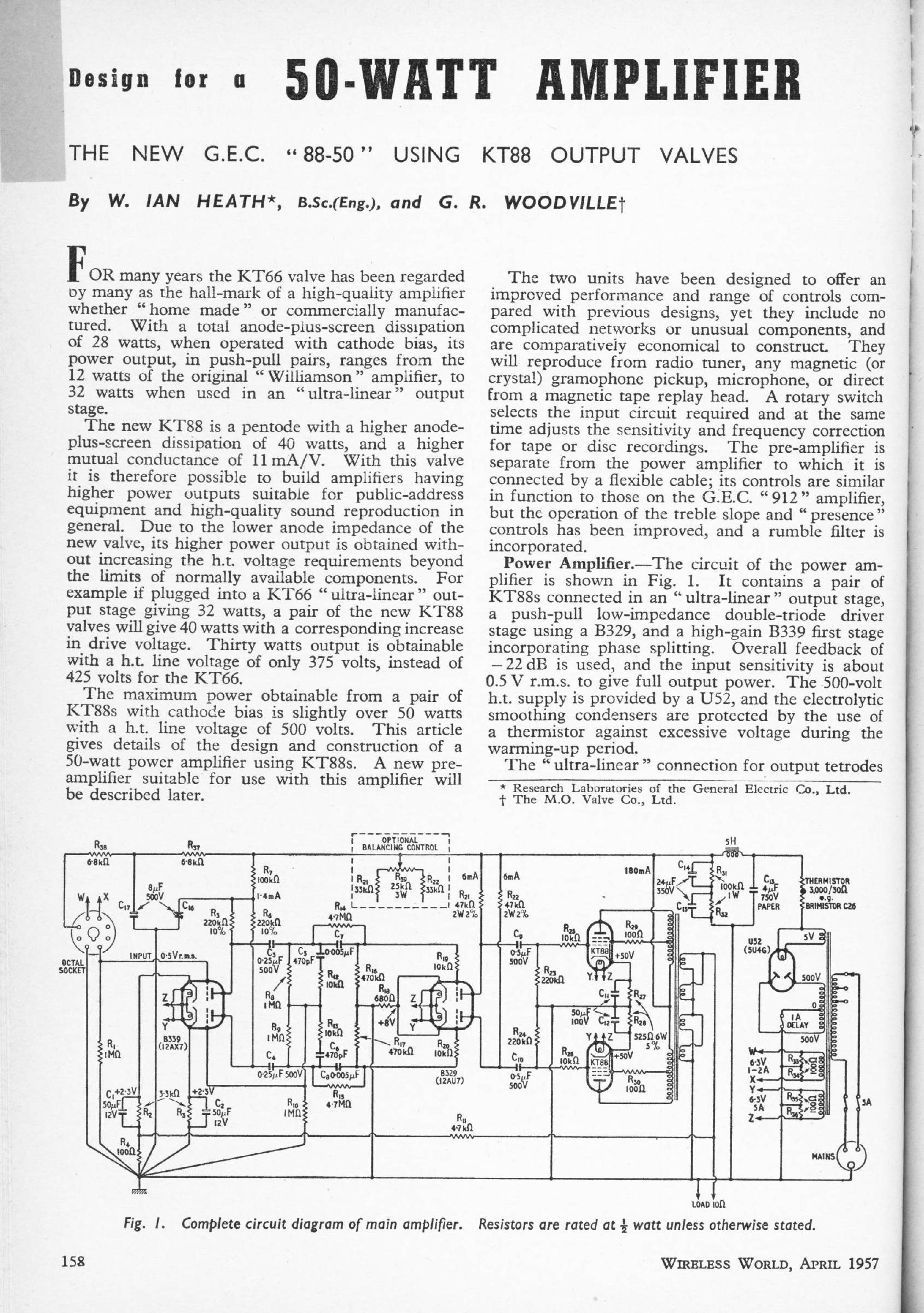
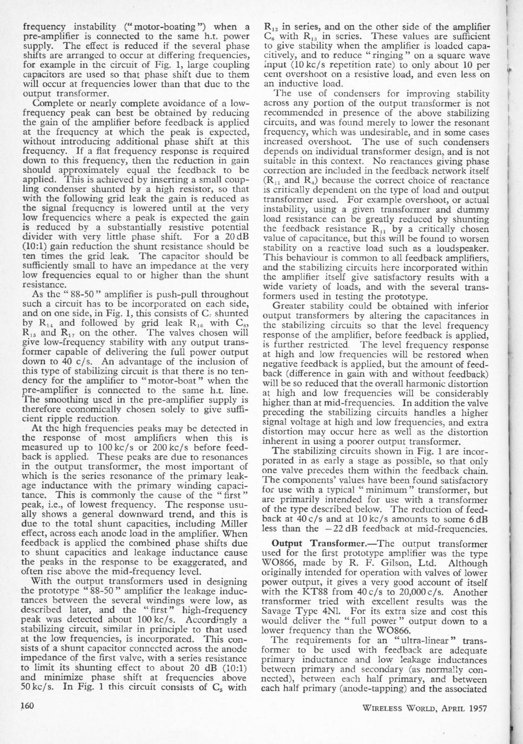
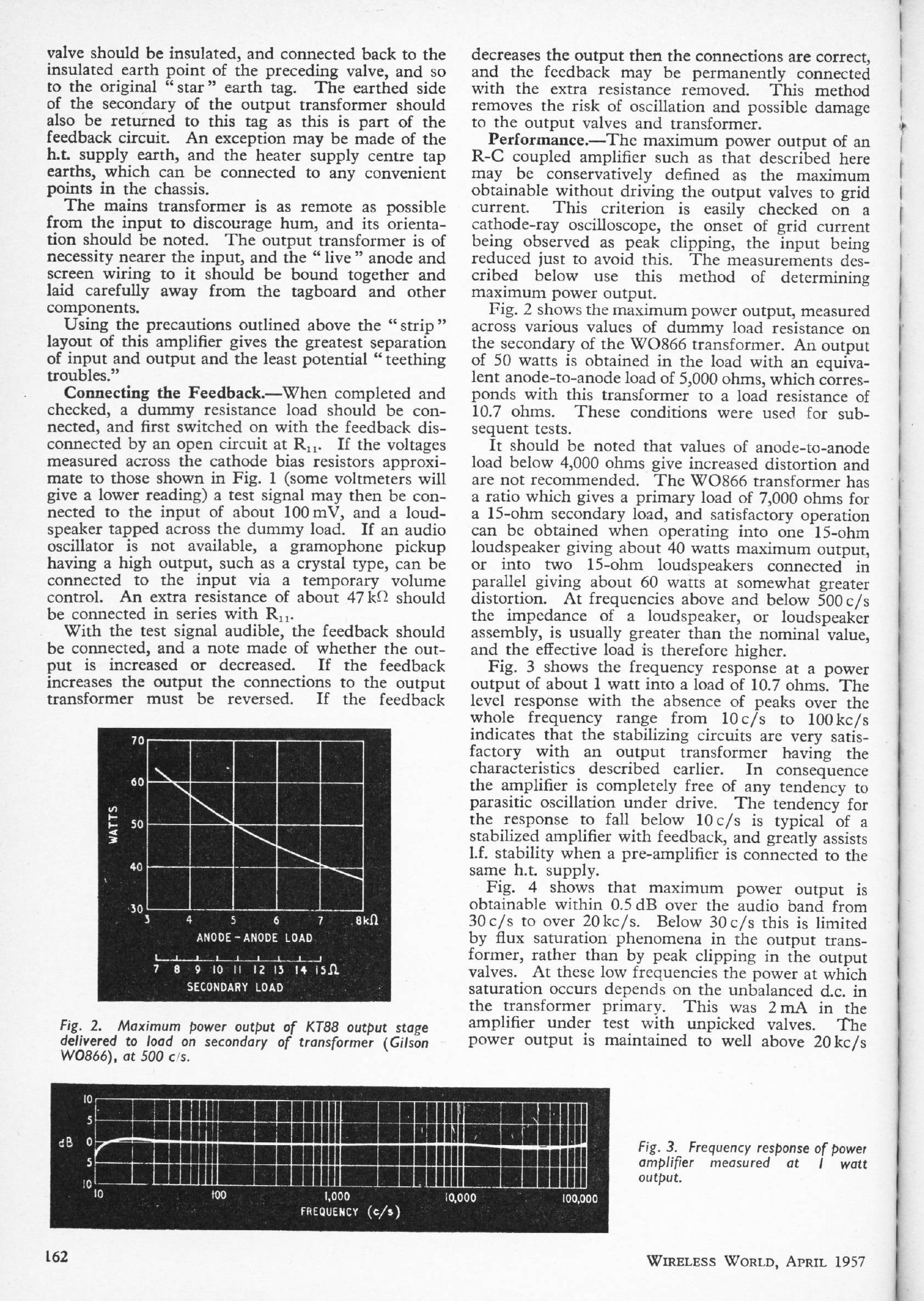
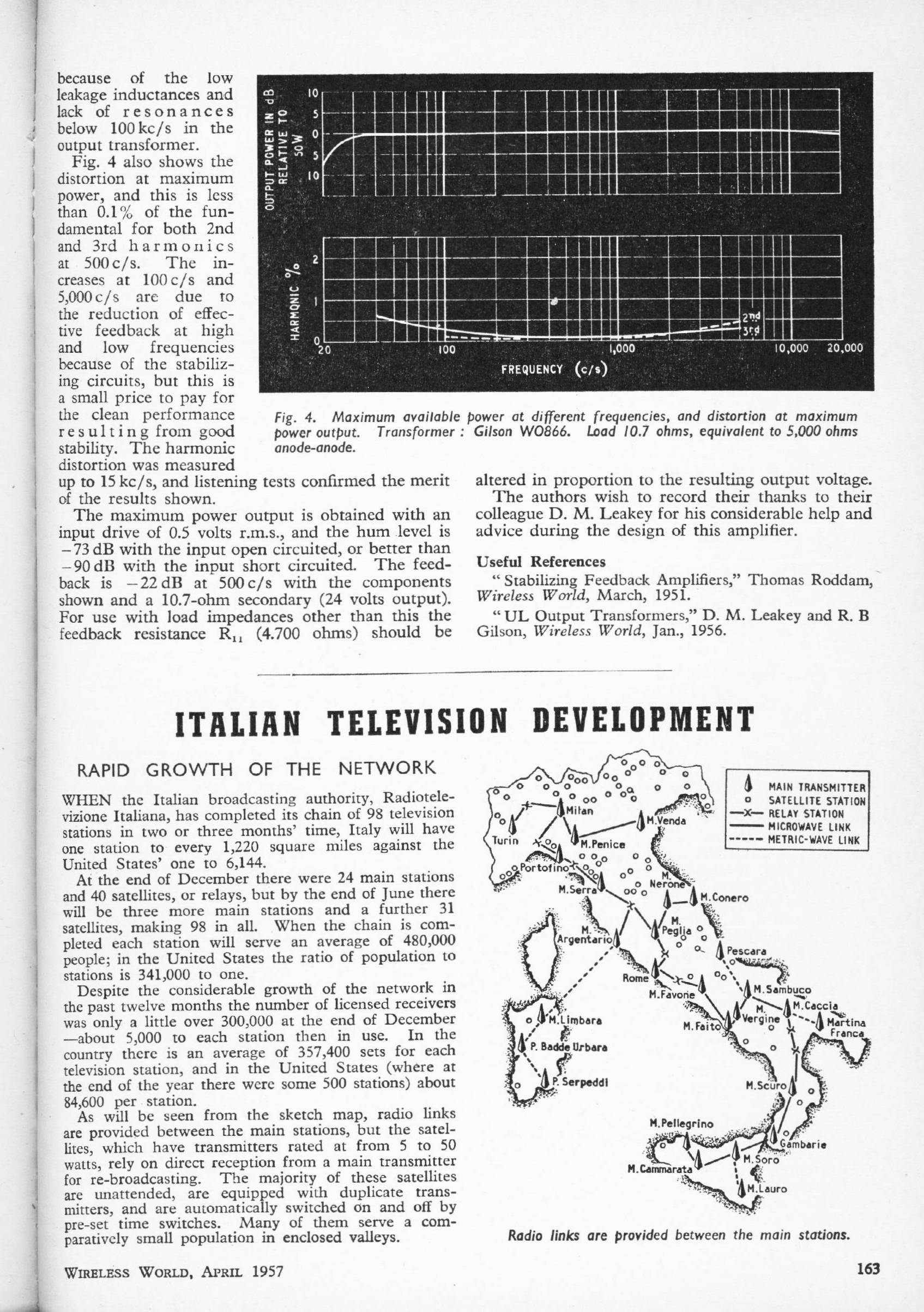
THE 88-50 POWER-AMPLIFIER: April 1957
W Heath & G Woodville
This 50W power amplifier used the relatively new KT88 (KT standing for 'kinkless tetrode') output valve which is described as a 'pentode', though it is actuually a beam tetrode. The supply rail is at an intimidating +500V.
|
|
|
| ||||||
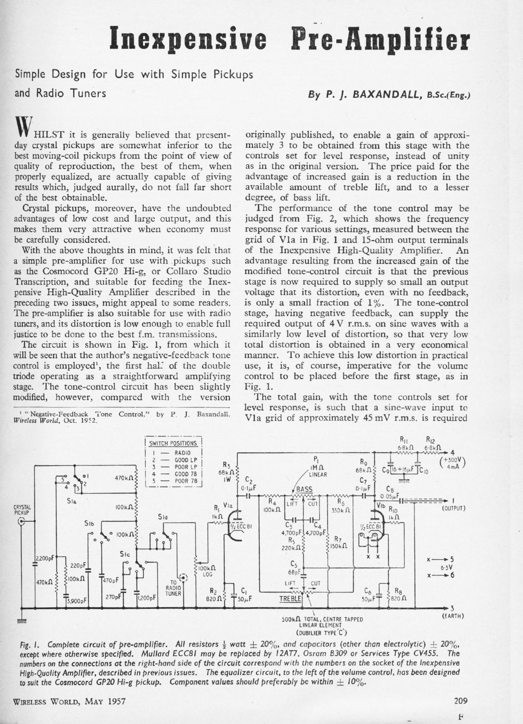
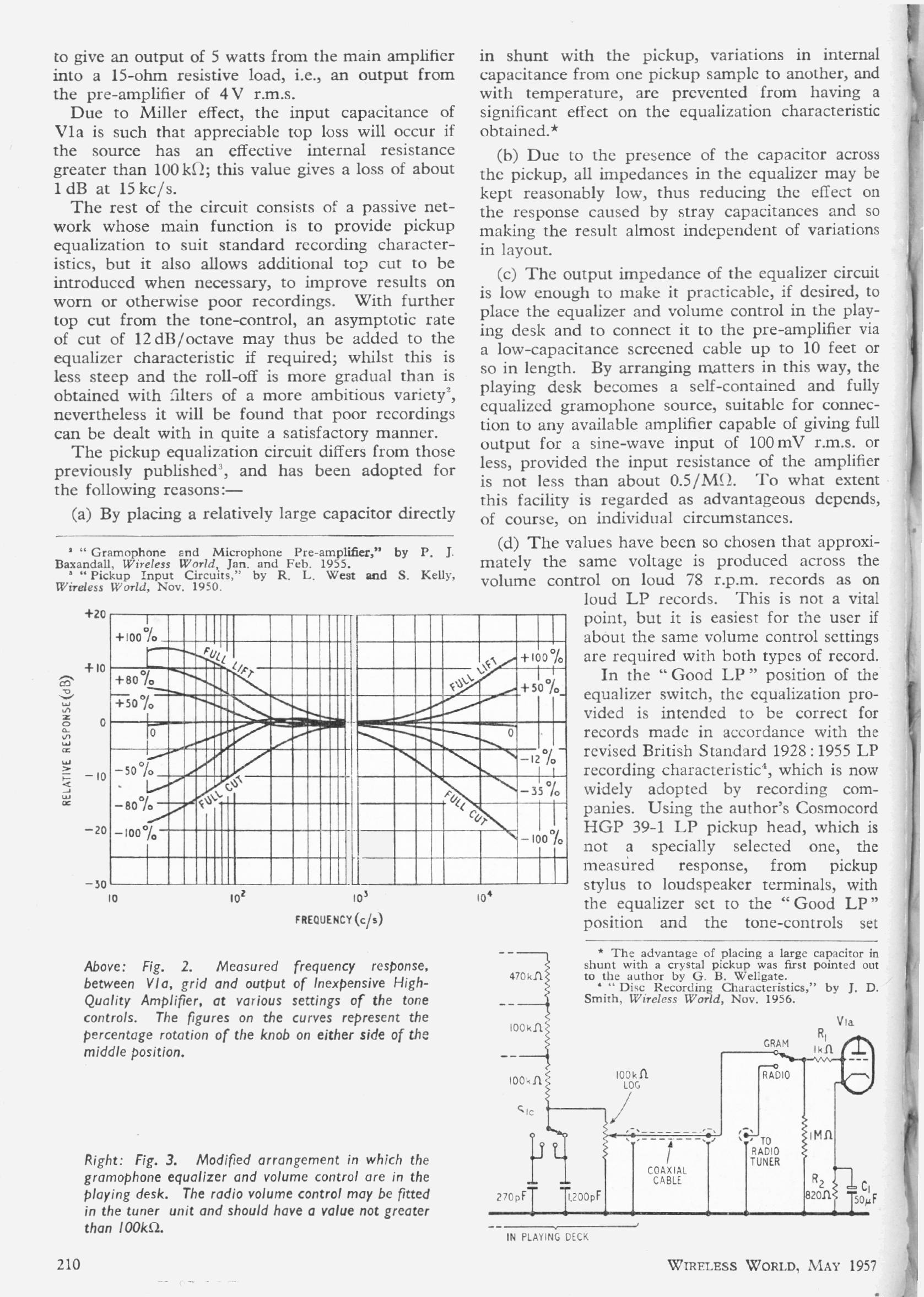
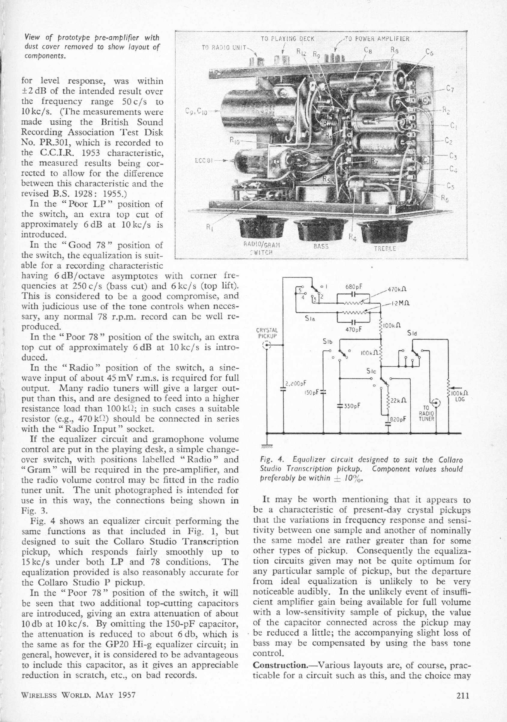
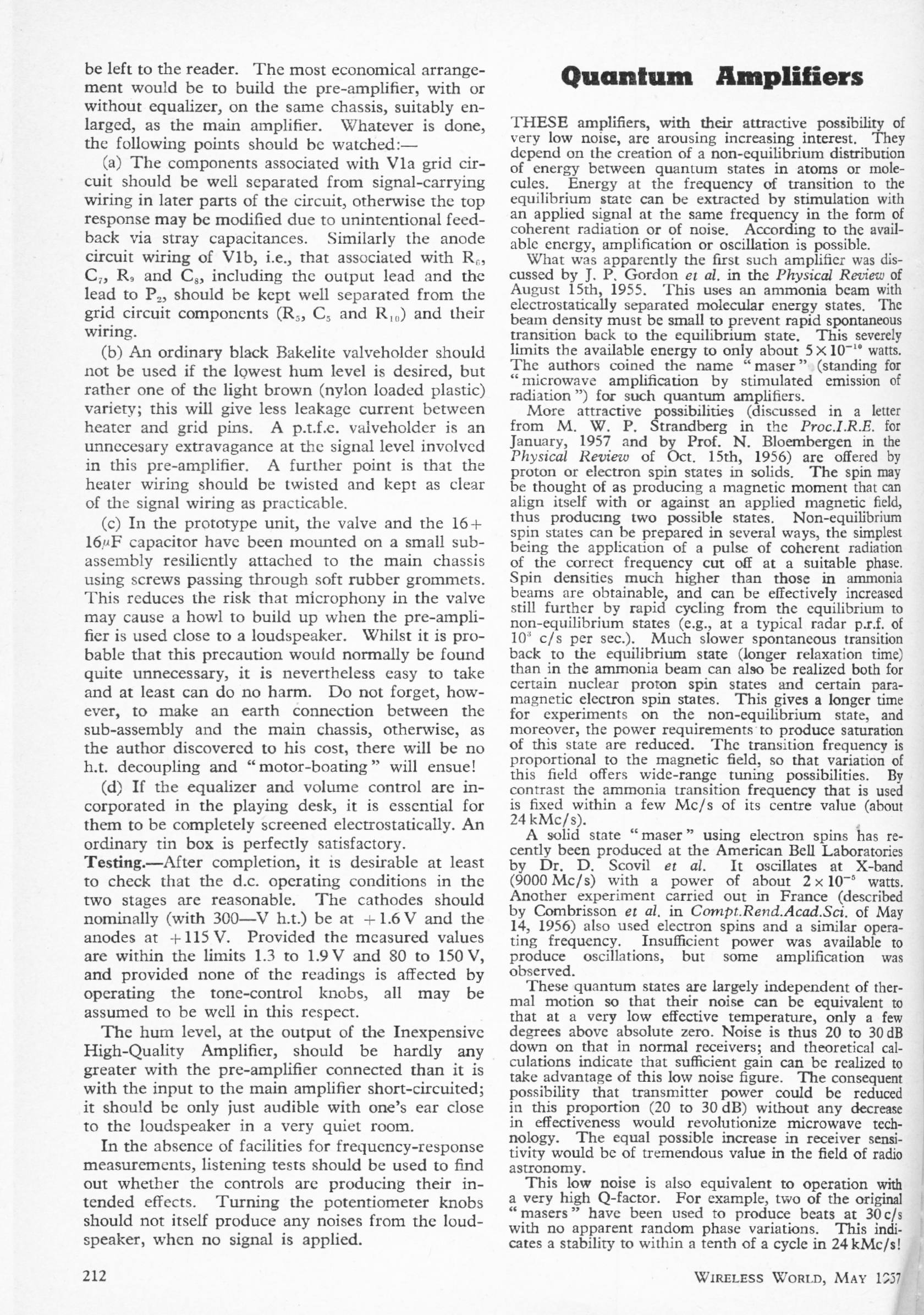
INEXPENSIVE PRE-AMPLIFIER: May 1957
Peter Baxandall
A much simpler design than the 1955 preamplifier, using two valves, or rather one double-triode. (ECC81) It was designed to feed the "Inexpensive High-Quality Amplifier" article of March 1957, and so has the high output level of 4 Vrms.
|
| ||||||
This preamplifier was designed for use with crystal (piezoelectric) cartrdges only, their high output allowing a simple design. This output was of the order of 100 - 200 mV at 1kHz, and back in the day there was much discussion as to whether they should be terminated in a very high impedance, or a relatively low resistance that would give cartridge-dependent equalisation. In an audio world where pretty much every technology has its adherents, nobody seems to want the crystal cartridge back.A version of the Baxandall tone control is fitted, still with the centre-tap on the treble control; the stage is here configured for a gain of three to reduce the demands on the voltage-amplification stage before it. The tone-control still gives fairly symmetrical curves flat at the centre settings, because the bass control is fed by the potential divider R6,R7 which has a loss of 3 times and an output impedance of 100 kOhm to match R4. Until today I was under the happy impression that I had invented this idea in 1983 for my Precision Preamplifier, but it looks as though Peter was more than somewhat ahead of me. Note the switched passive equalisation networks for "LP" and "78" at the crystal pickup input. | |||||||
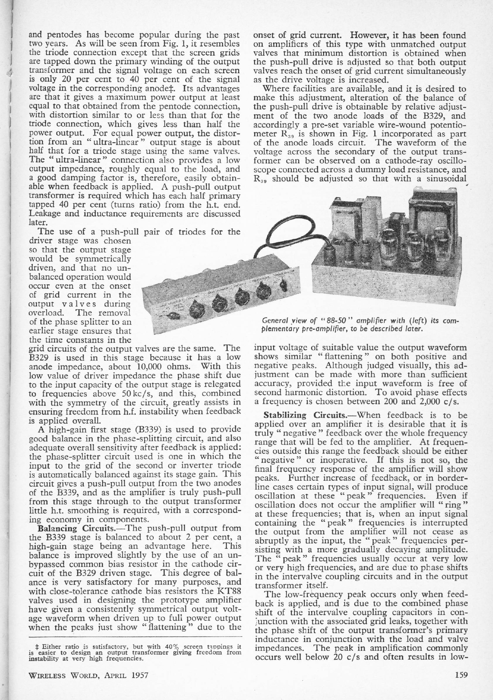
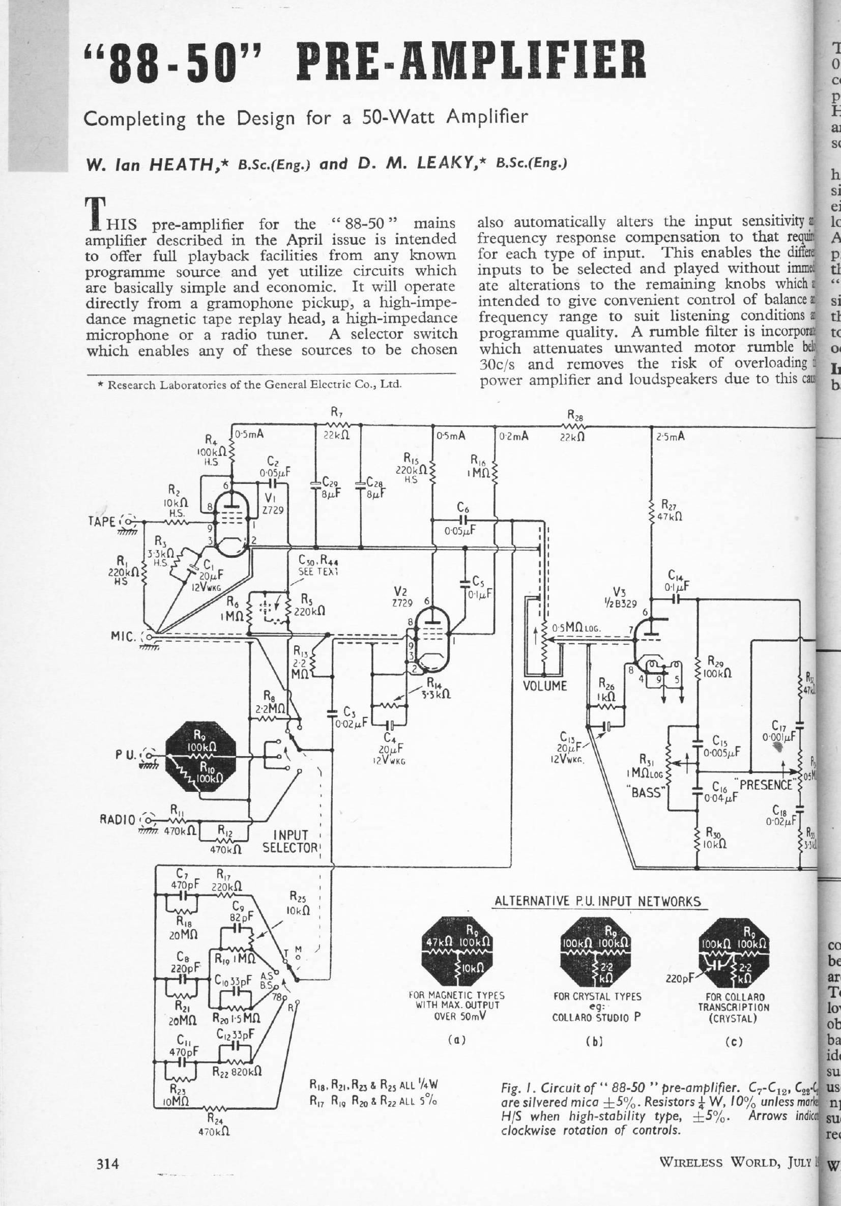
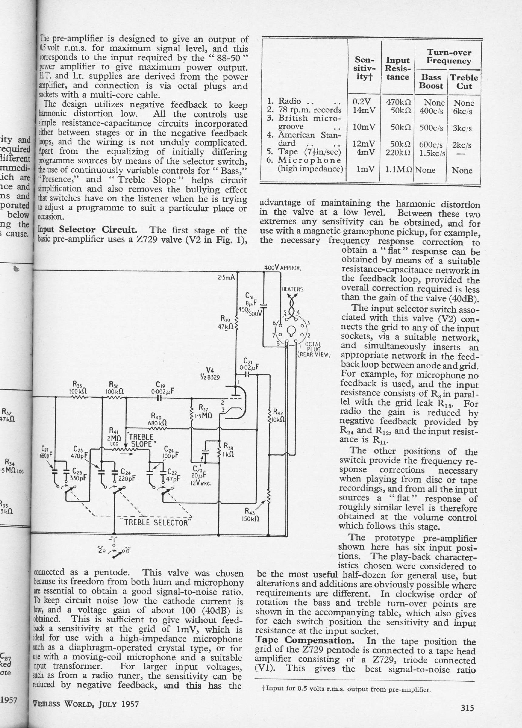
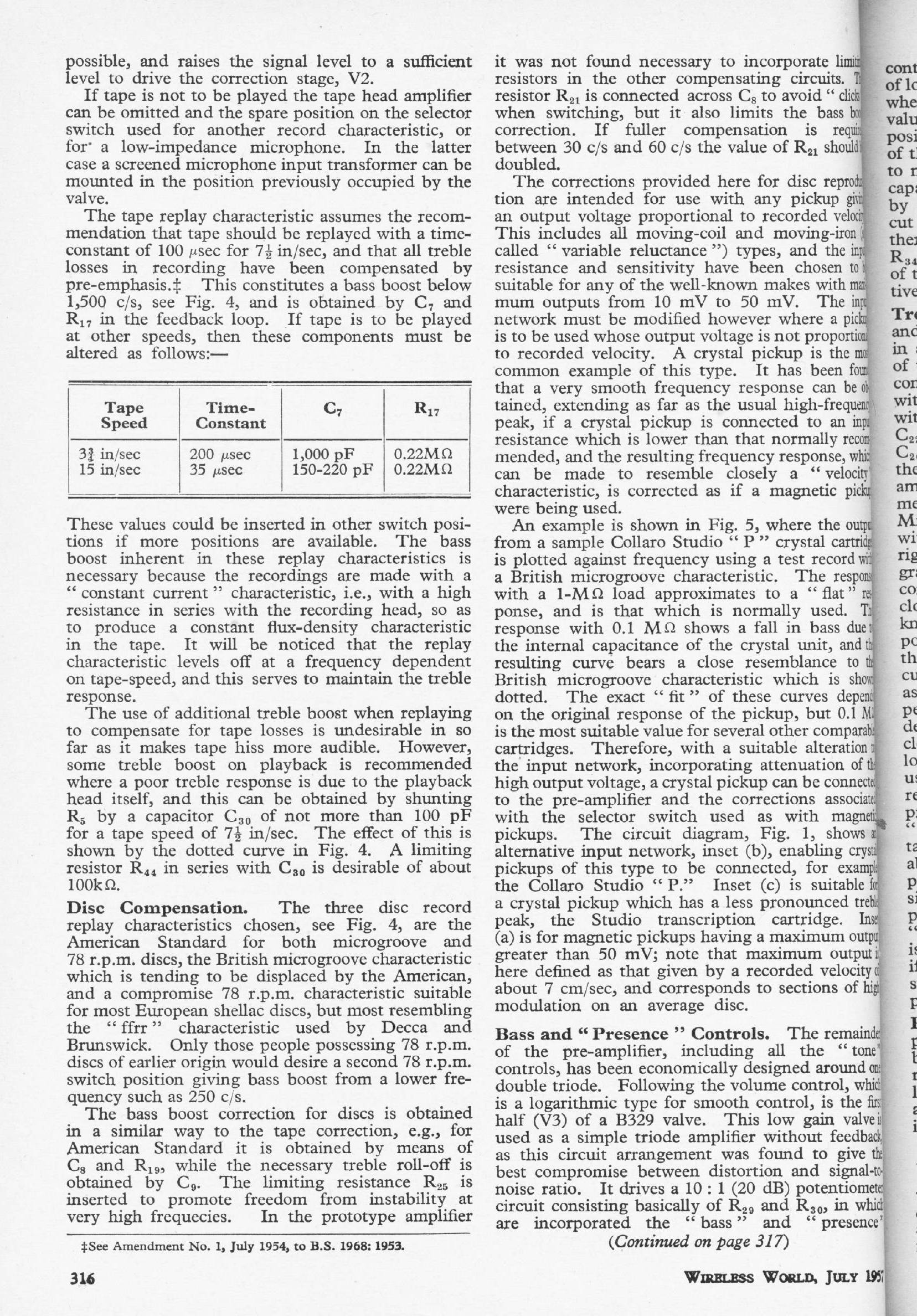
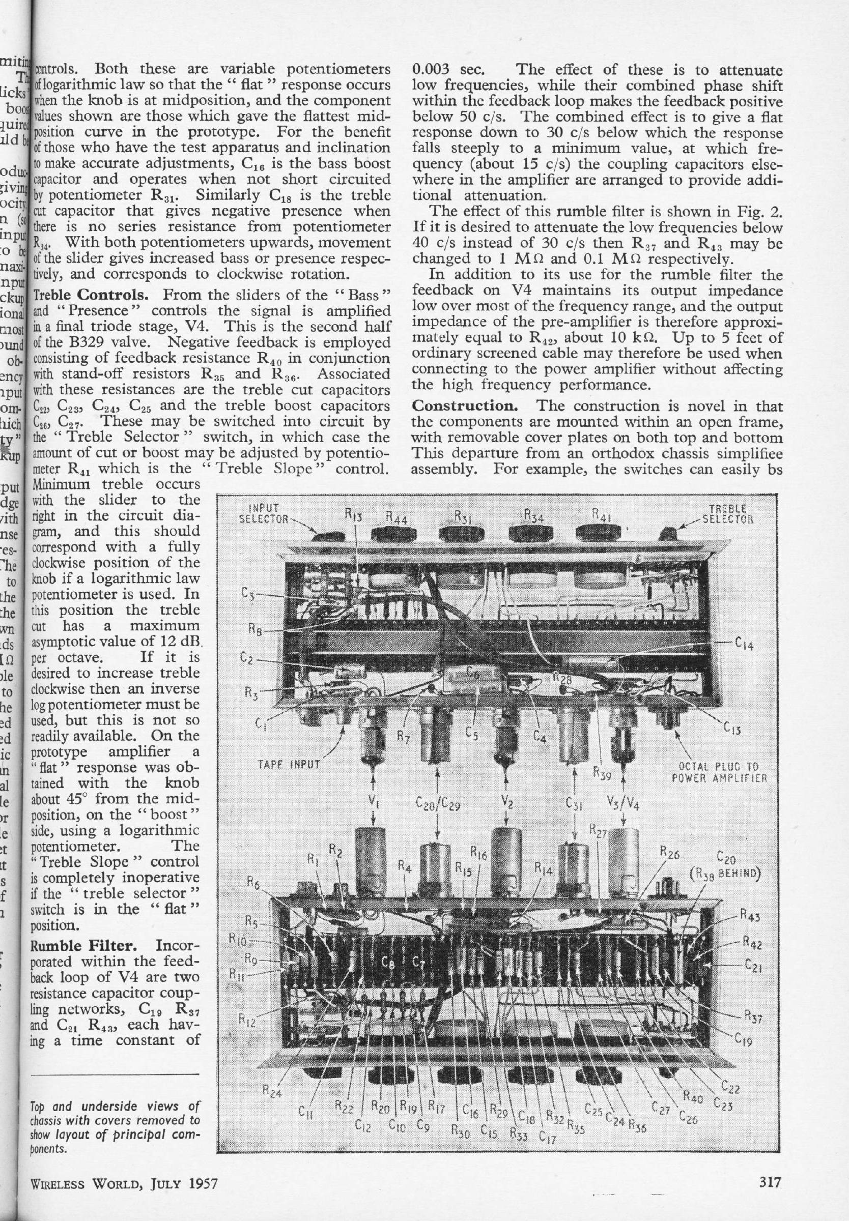
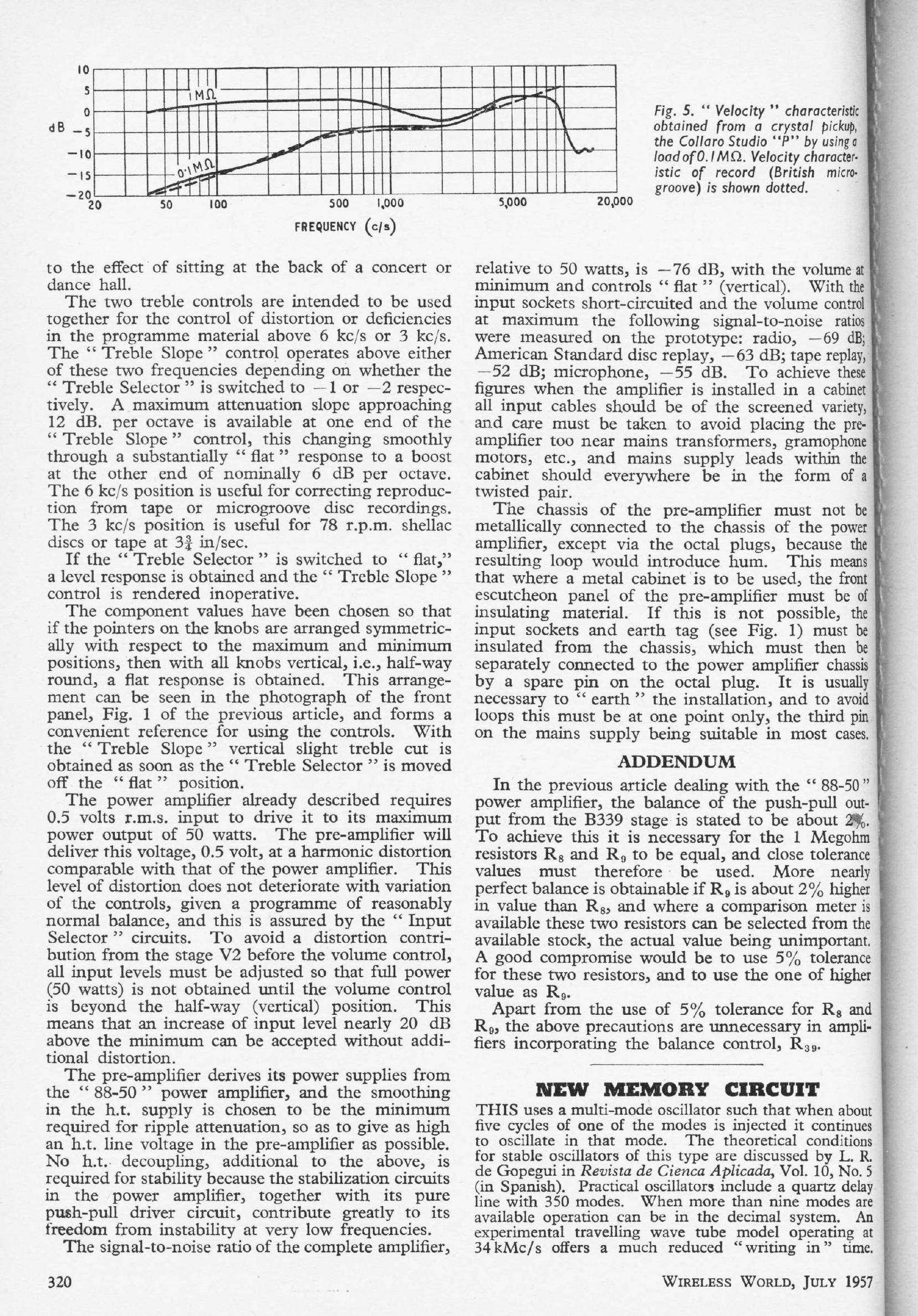
THE 88-50 PREAMPLIFIER: July 1957
W Heath & D M Leakey
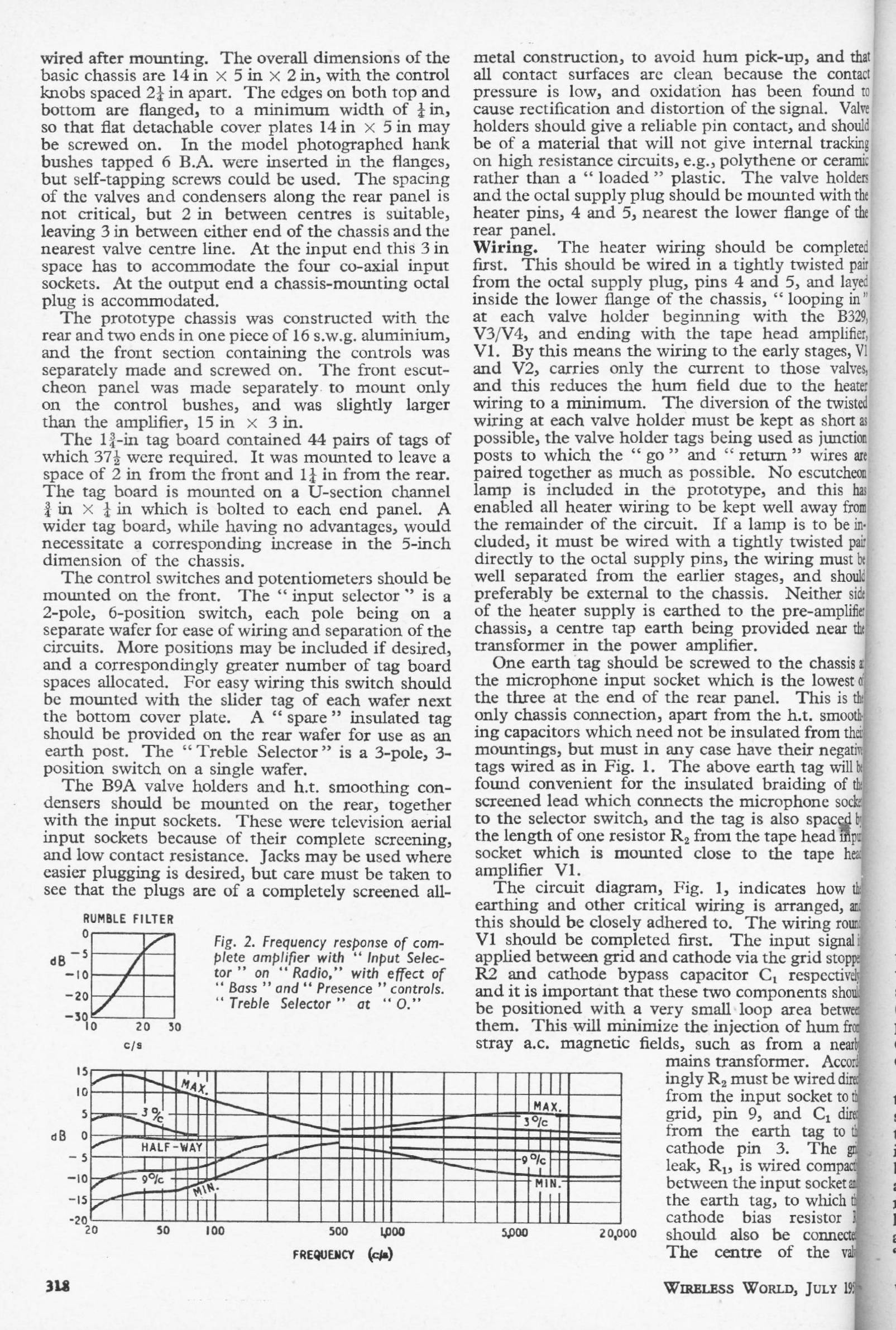
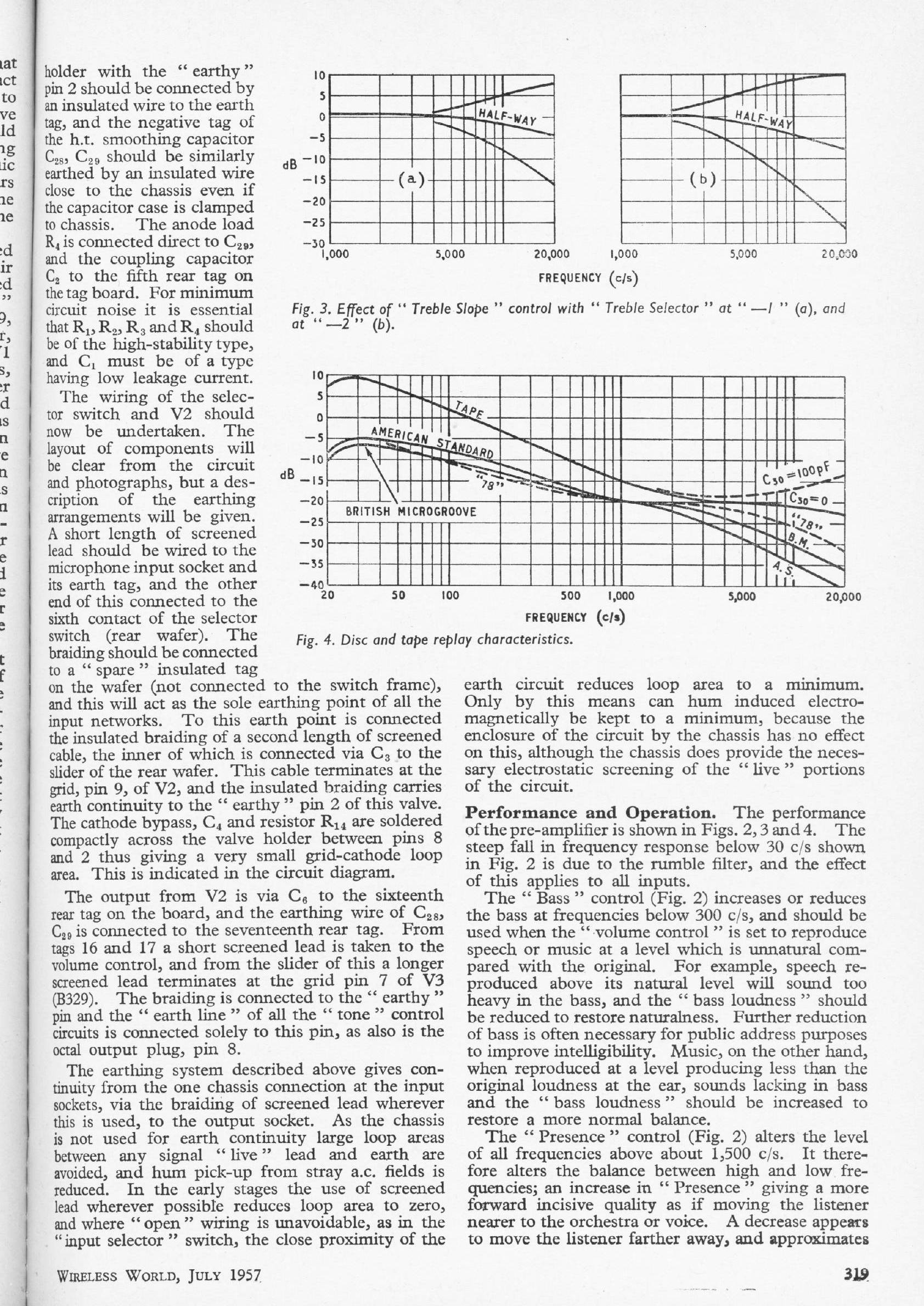
This preamplifier partners the 88-50 power amplifier published in April 1957; that article is available just above. It use two pentodes and a double triode. The article describes the design decisions taken in detail.
|
| |||||||
|
| |||||||
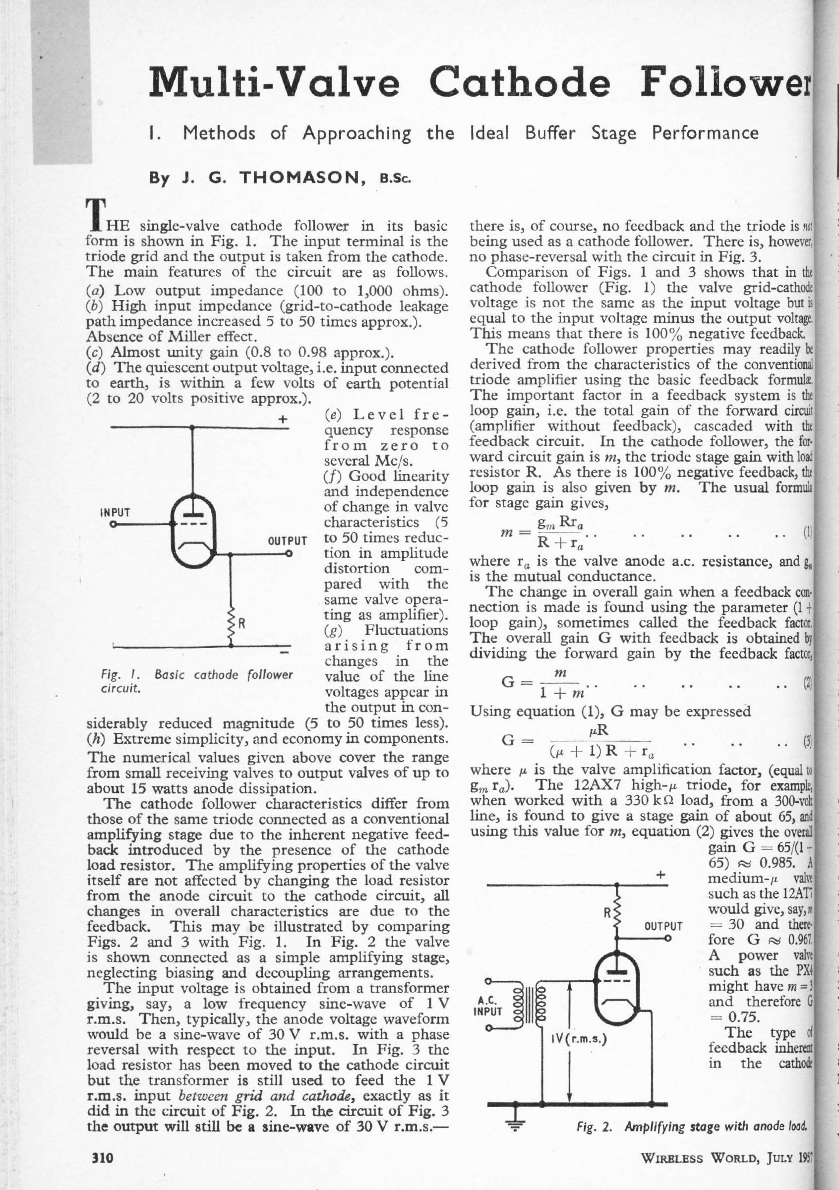
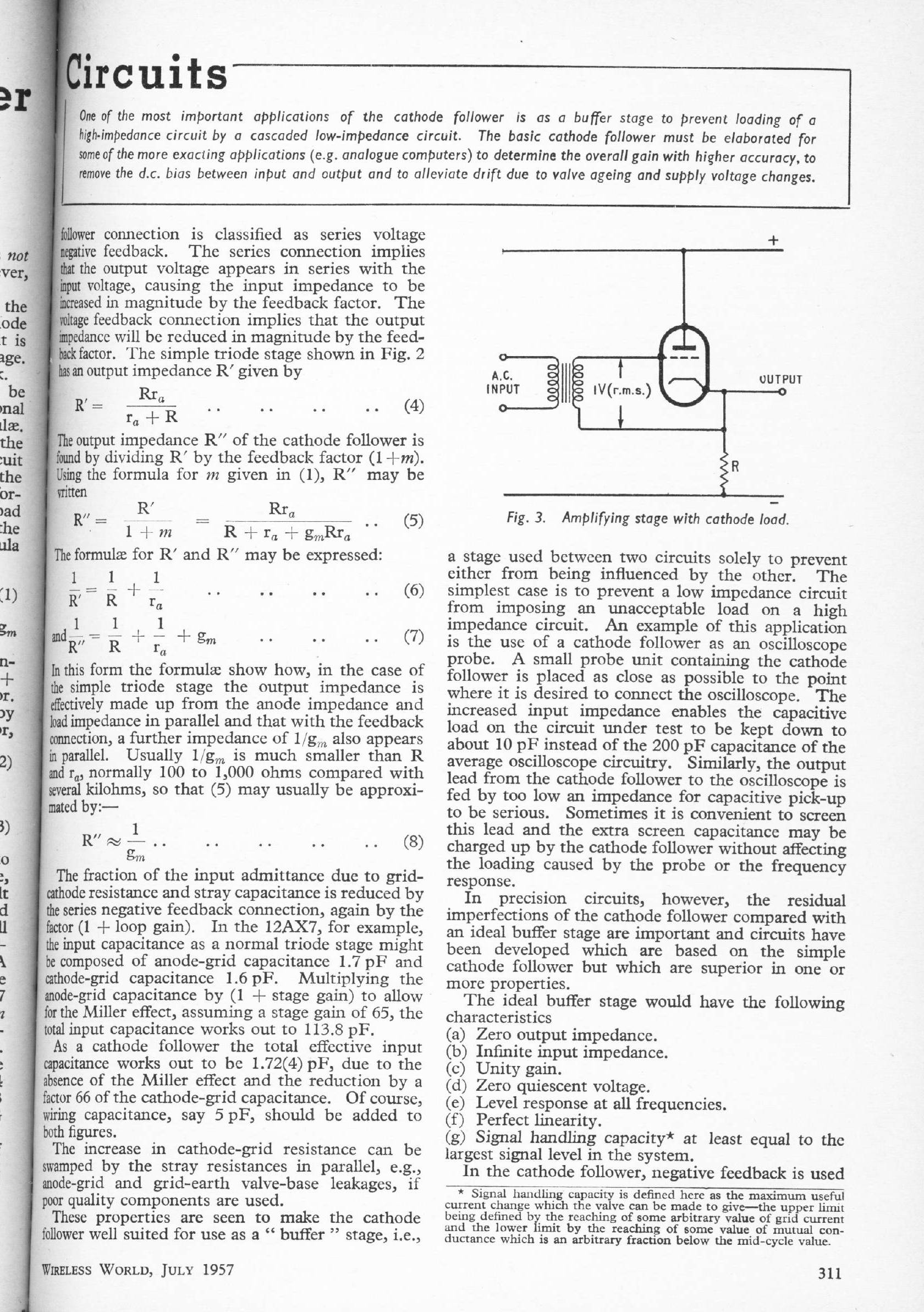
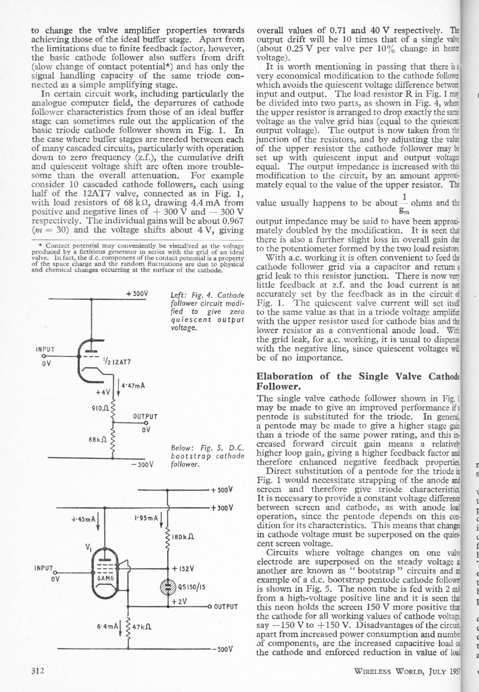
MULTI-VALVE CATHODE FOLLOWERS Part 1: July 1957
J G Thomason
This article was written in the days when adding an extra active device was a serious matter because the cost was high.
|
|
MULTI-VALVE CATHODE FOLLOWERS Part 2: Aug 1957
J G Thomason
This is a fascinating article, but not much applicable to solid-state applications.
|
|
|
HOW LITTLE DISTORTION CAN WE HEAR?: Sept 1957
M Lazenby
Ear distortion and masking effects
|
| ||||||
| This article references some classic research on the subject. | ||||||
MORE TRANSFORMERLESS AMPLIFIERS: Mar 1958
Author unknown (WW staff?)
A follow-up to the February 1957 article above.
| This article includes output stage configurations put forward by Philips, and by Peterson and Sinclair. In both cases the loudspeakers have 800-Ohm voicecoils, making these stages practical if not perhaps very linear; what compromises there might be in making such loudspeakers I do not know. Driving a conventional 8-Ohm loudspeaker directly with valves is of course much more difficult. |
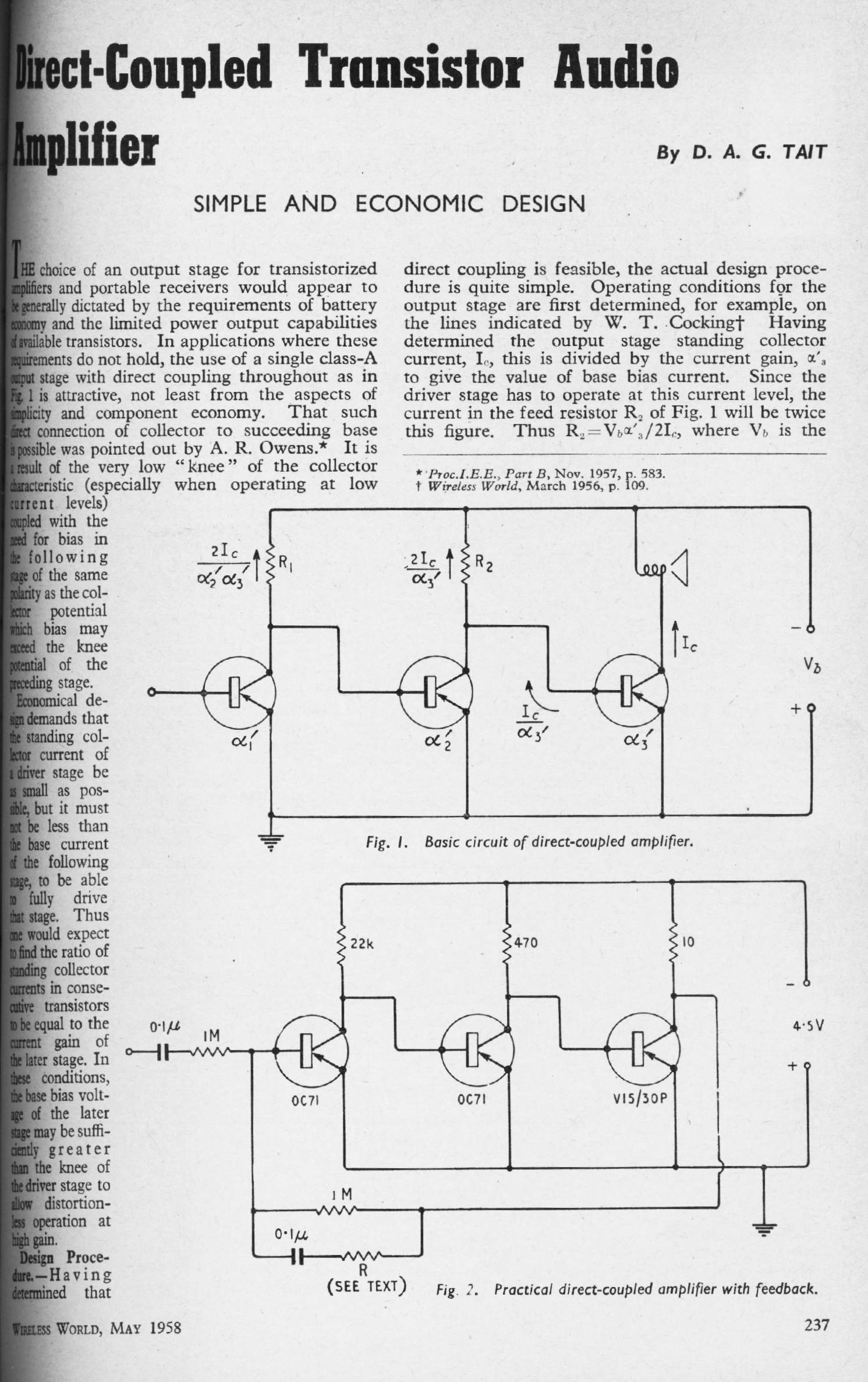
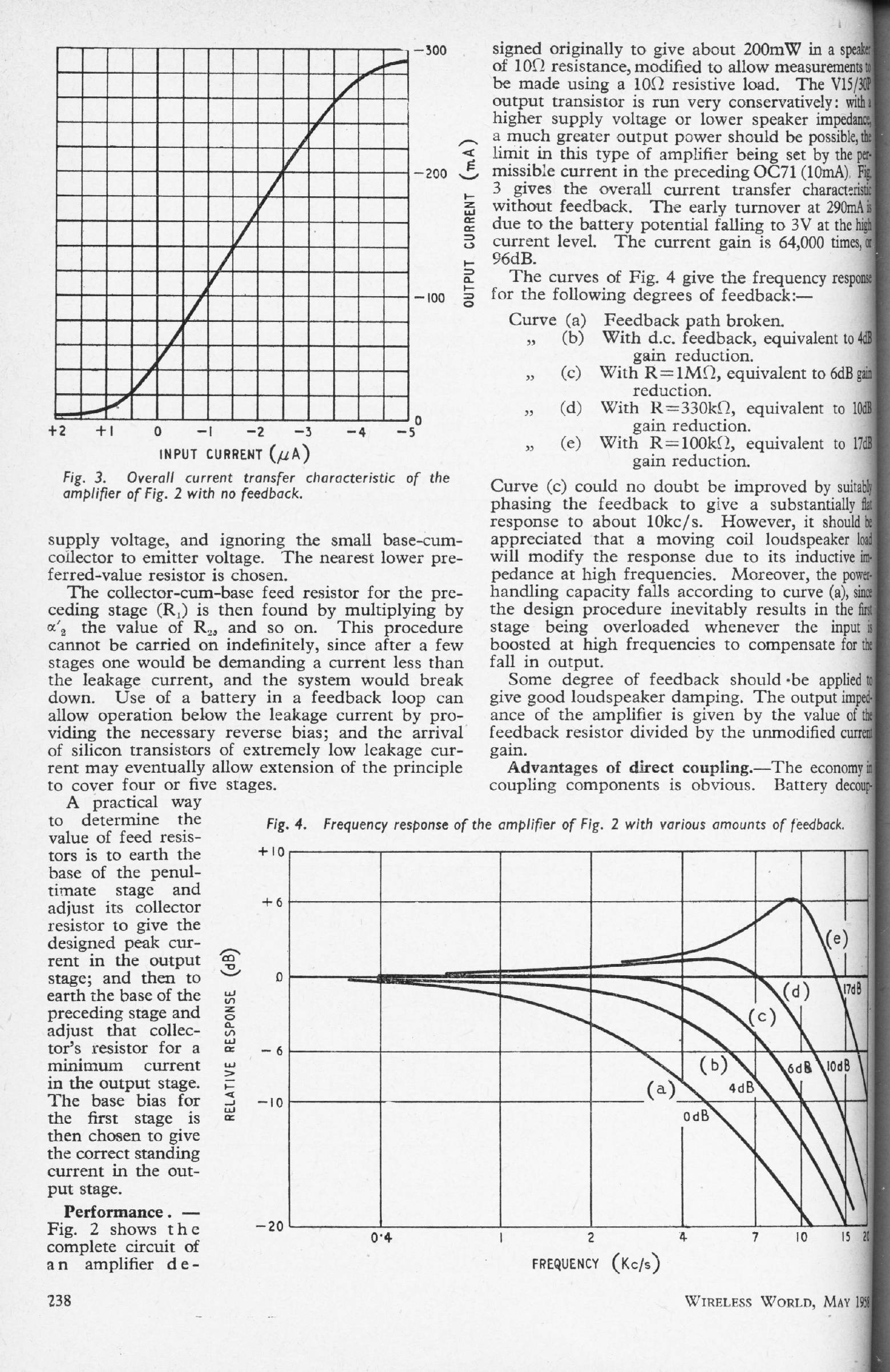
DC-COUPLED TRANSISTOR AUDIO AMPLIFIER: May 1958
D A G Tait
This is one of the earliest designs for a transistor power amplifier that appeared in WW. It is a three-transistor circuit in single-ended Class-A, with shunt feedback. The DC standing current of the output stage passes through the coil of the loudspeaker, which I would have thought would made its already mediocre linearity a good deal worse, though the author states it will not be 'troublesome'. Even allowing for the date, this seems to be a rather crude design. No distortion figures are given.
|
|
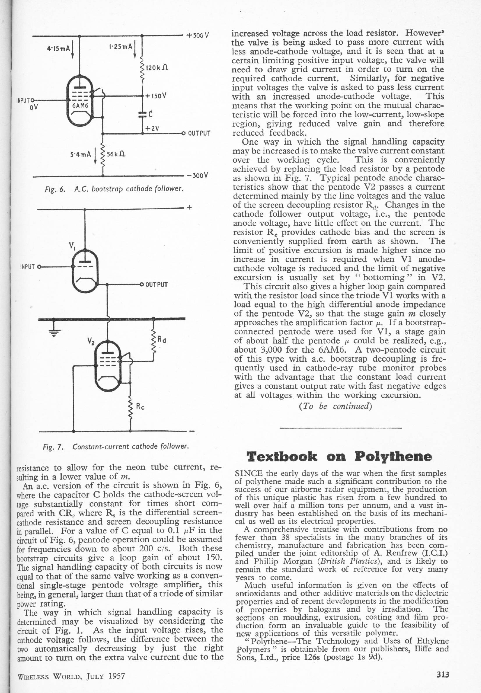
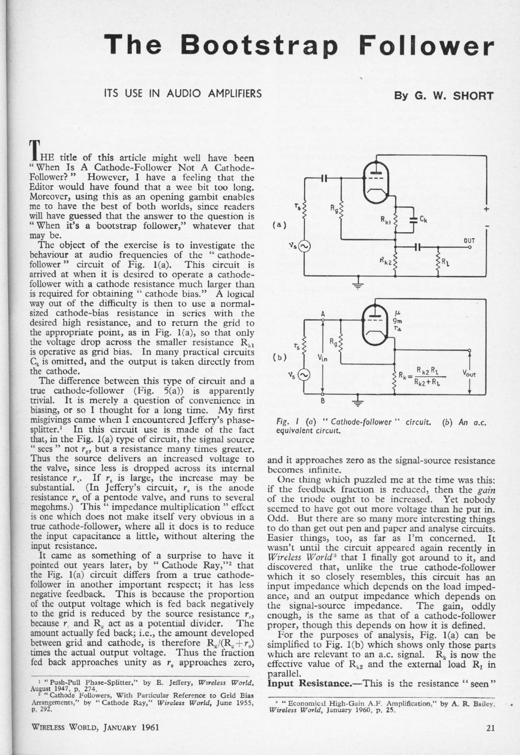
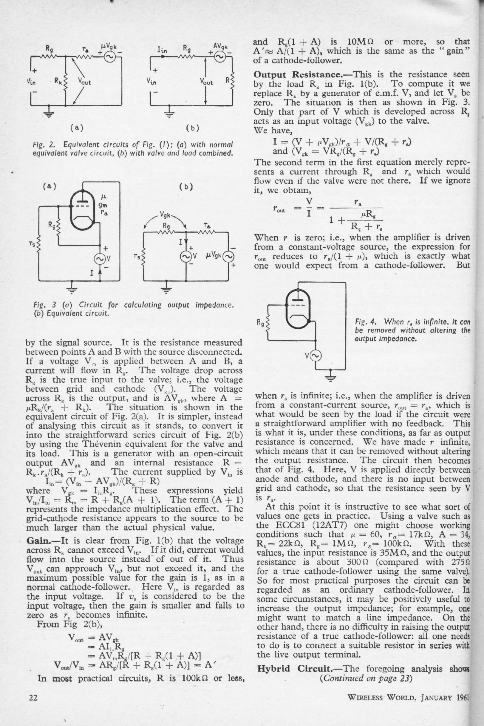
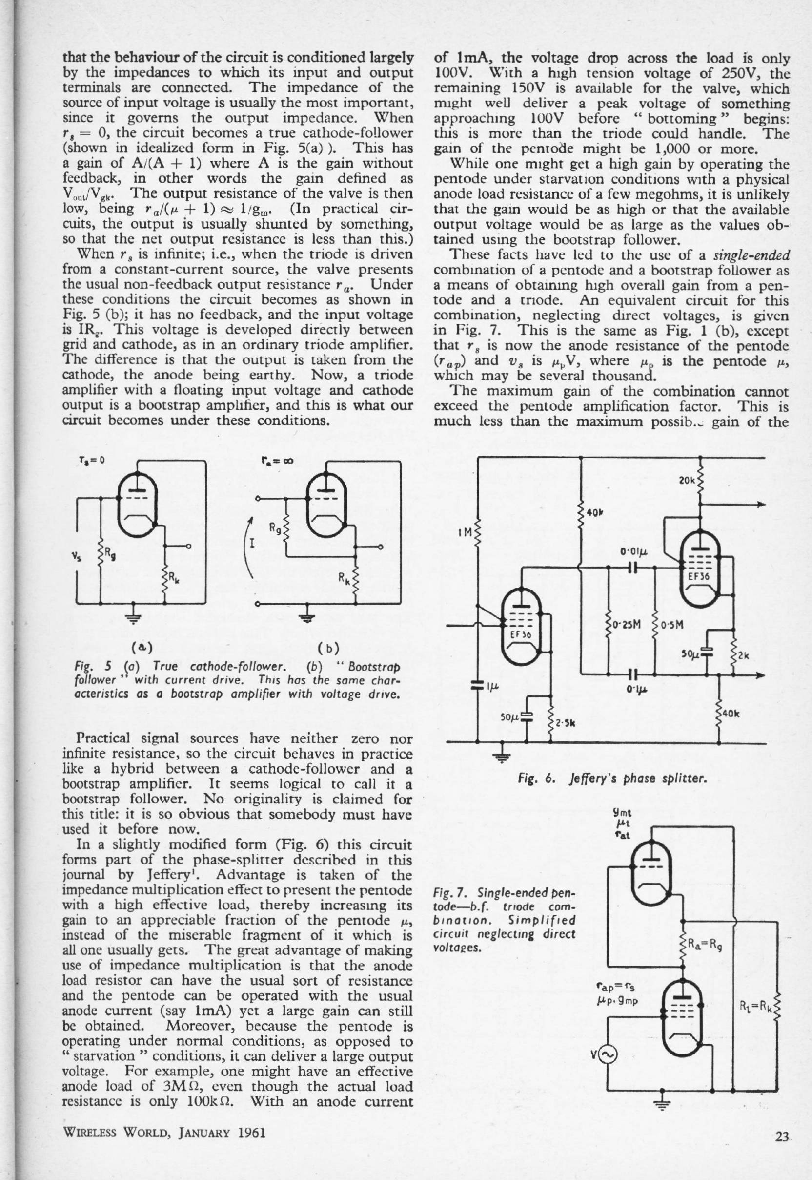
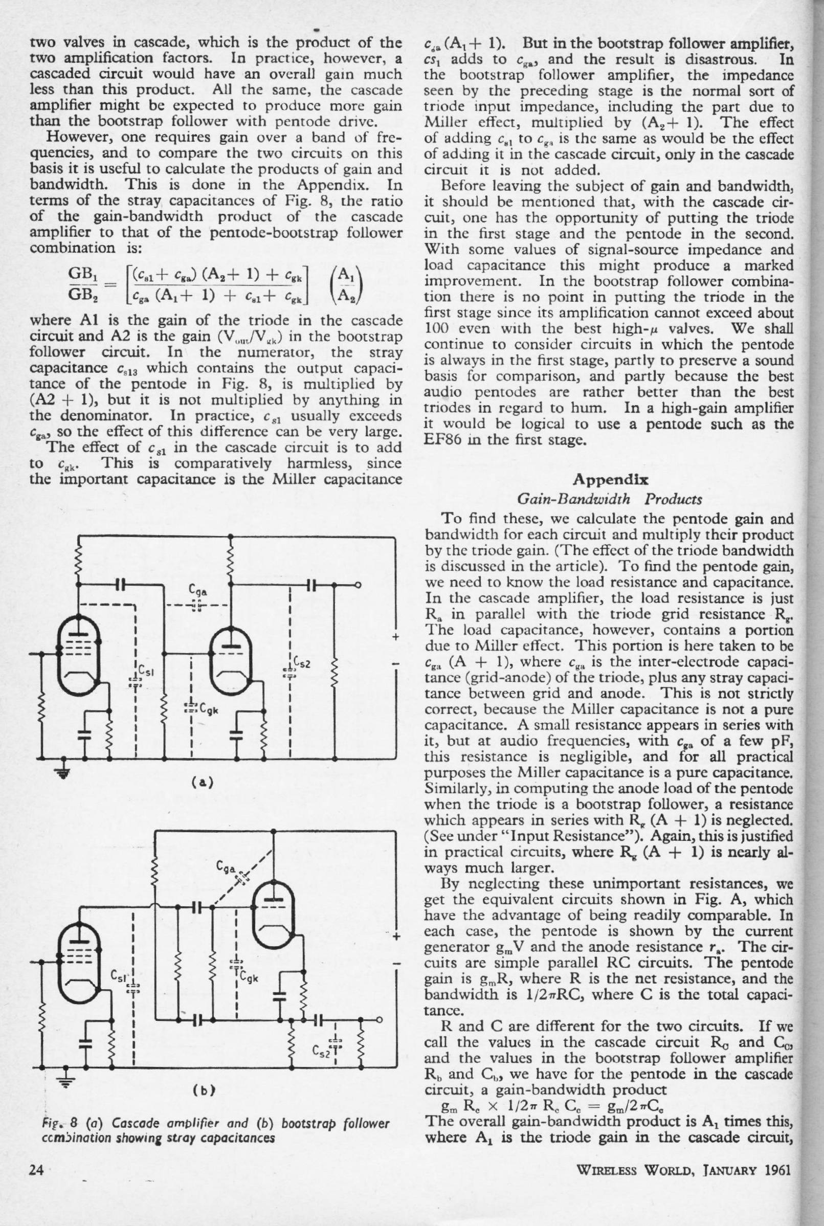
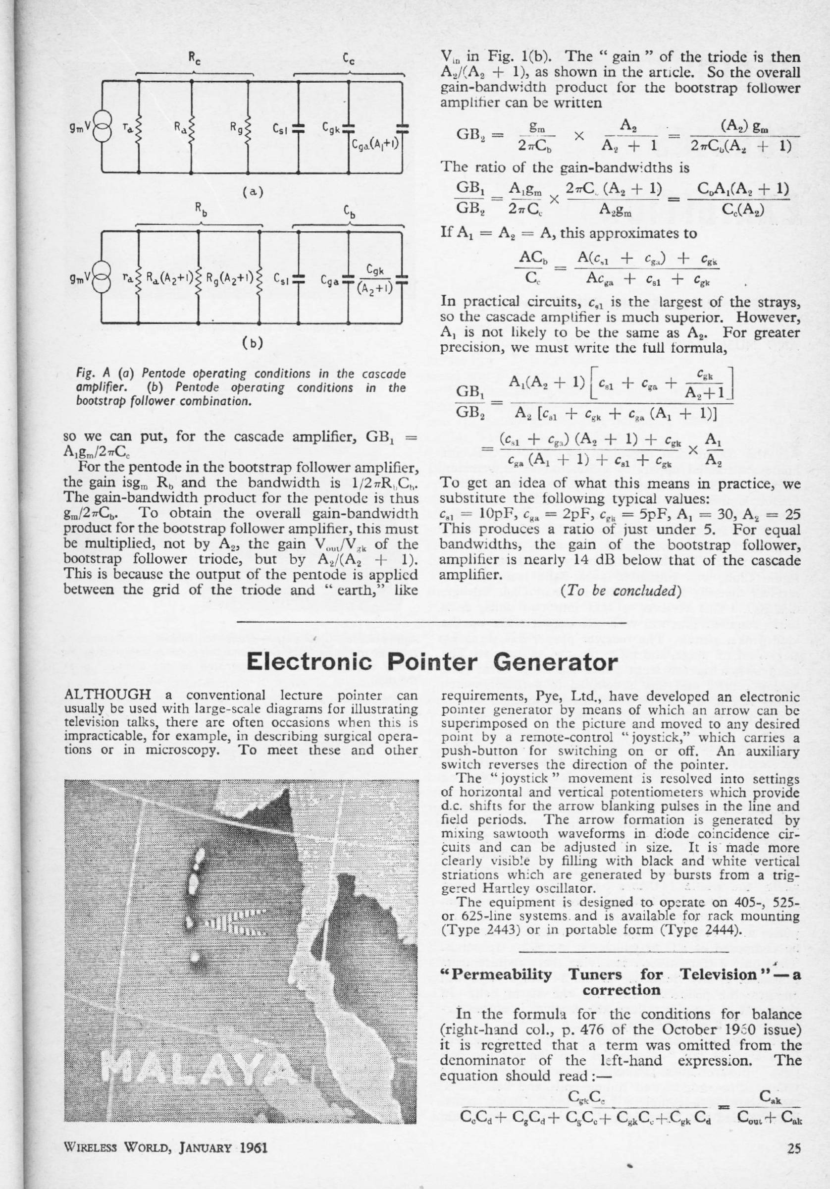
THE BOOTSTRAP FOLLOWER: Jan 1961
G W Short
A close examination of the properties of the cathode follower and variations thereon.
|
|
|
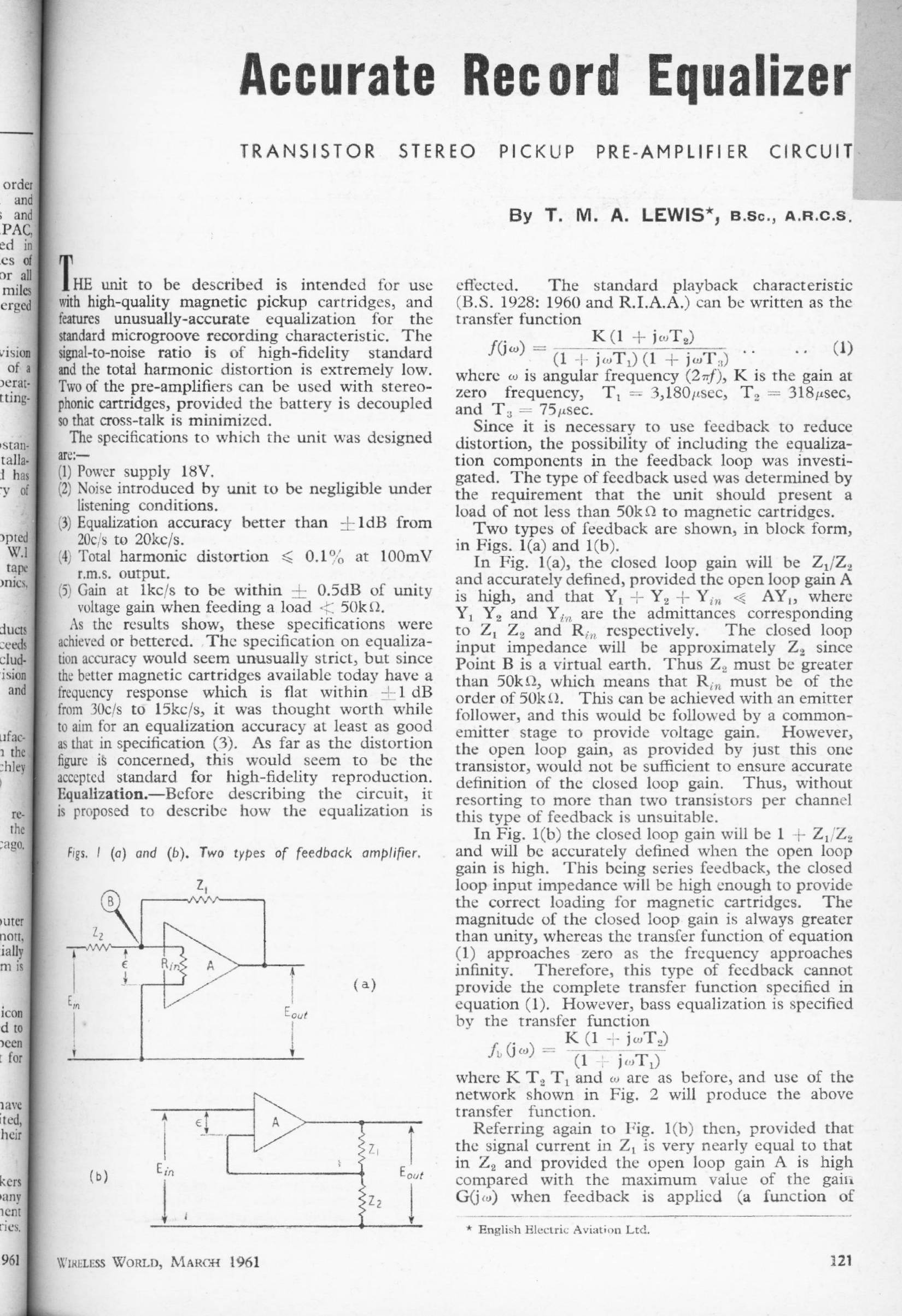
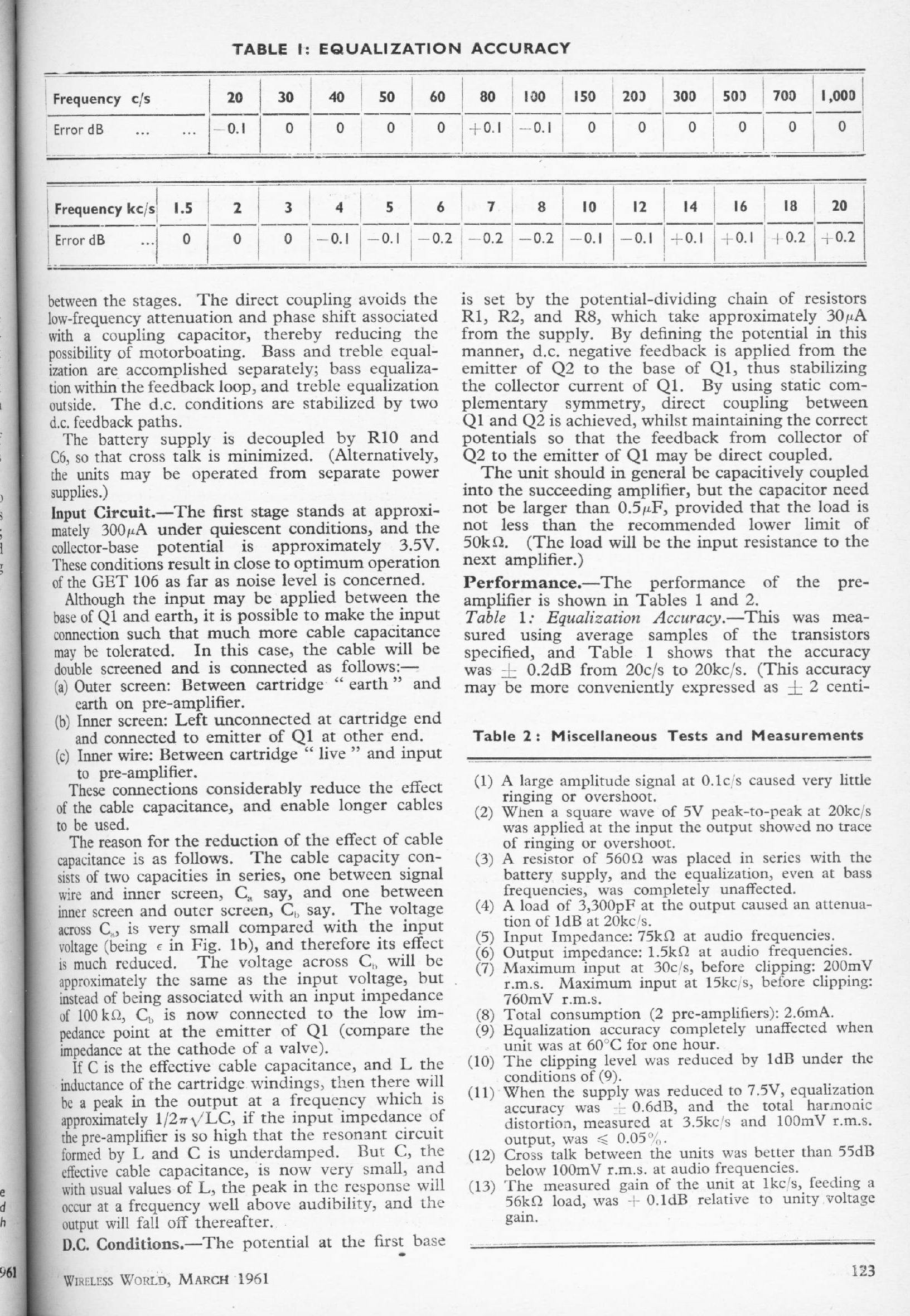
ACCURATE RECORD EQUALISER: Mar 1961
T M A Lewis
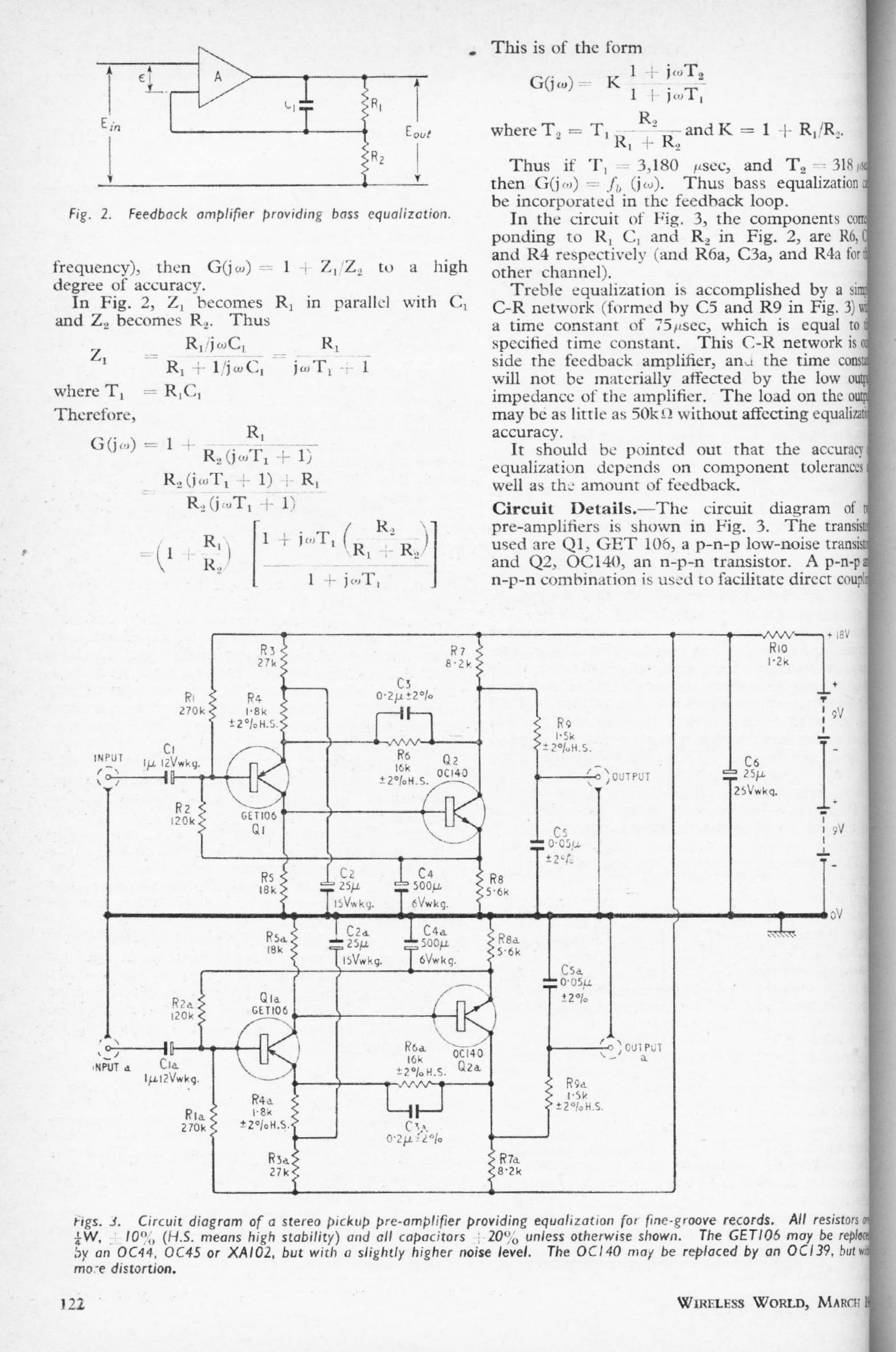
Semi-passive RIAA is not a new idea. Here the LF part of the RIAA characteristic is implemented by frequency-dependent series feedback, while the HF roll-off is done by a passive RDC network after the two-transistor amplifier.
|
|
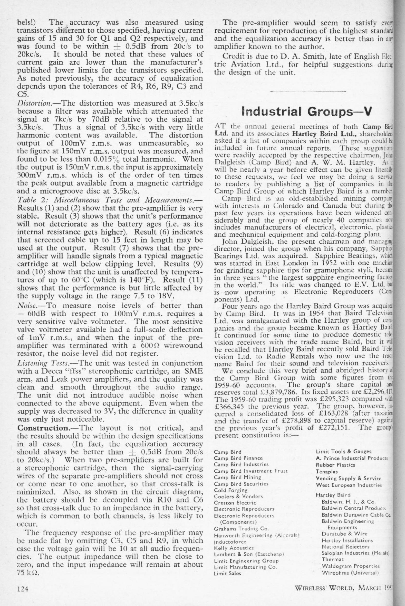
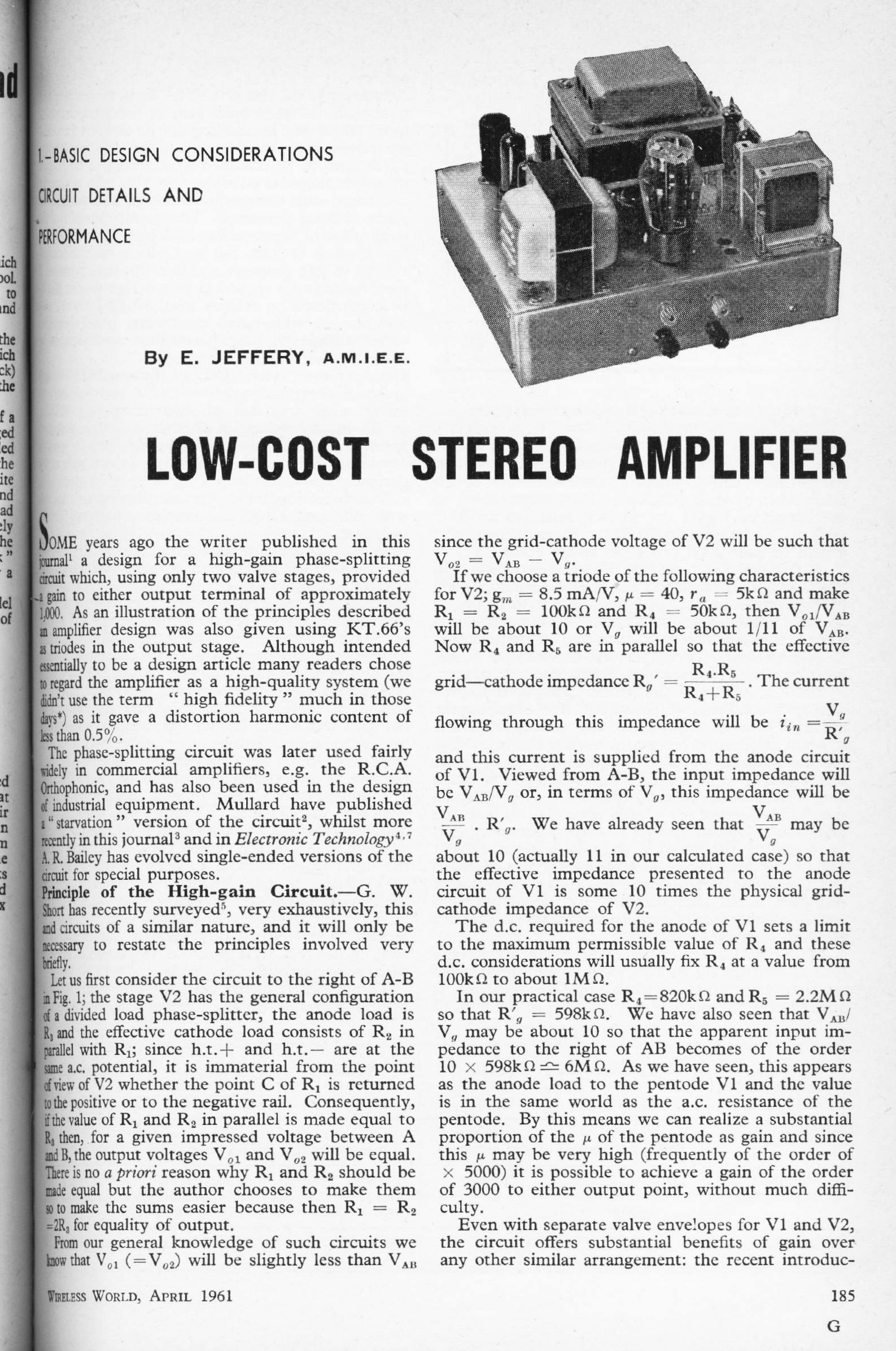
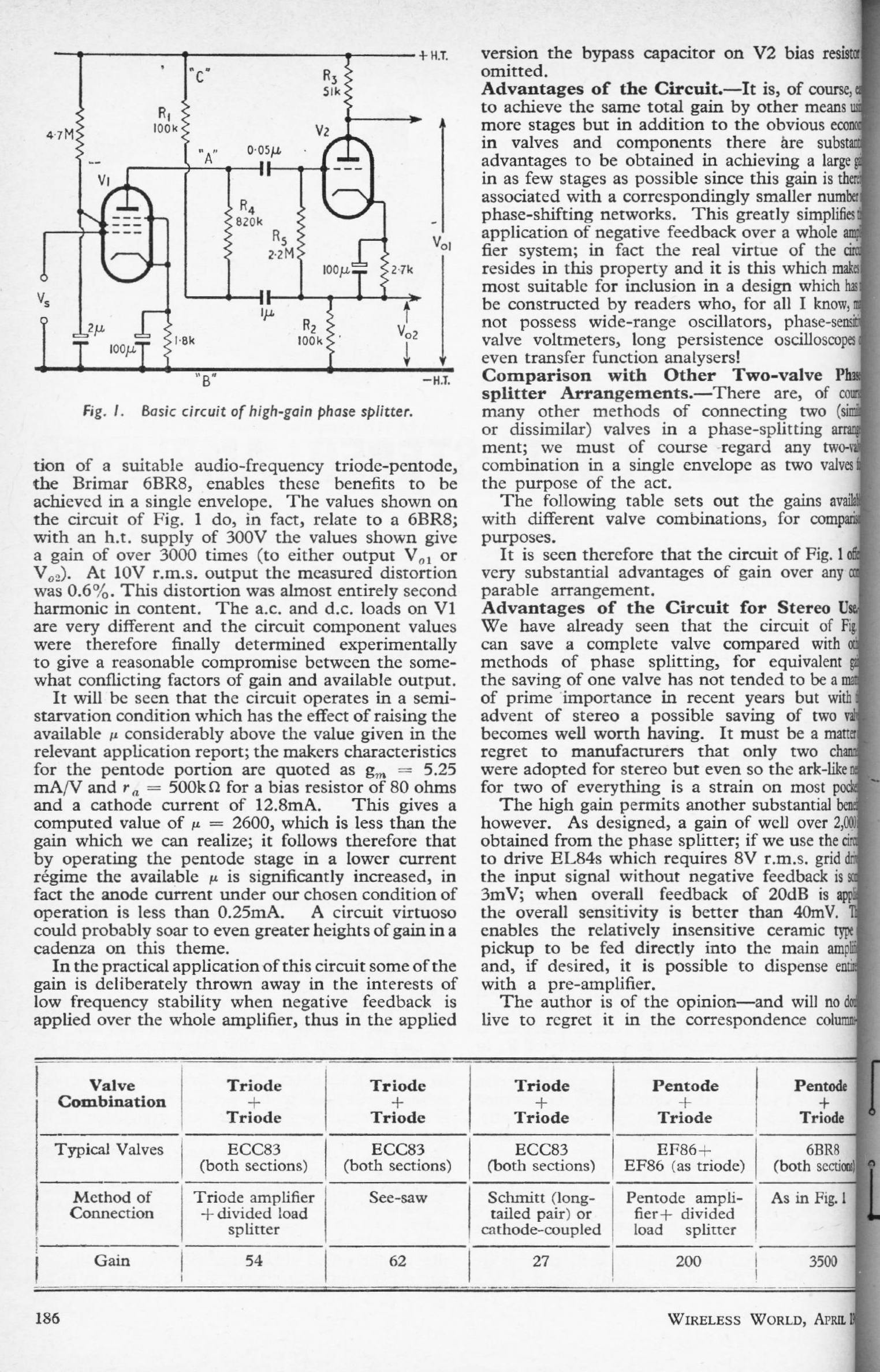
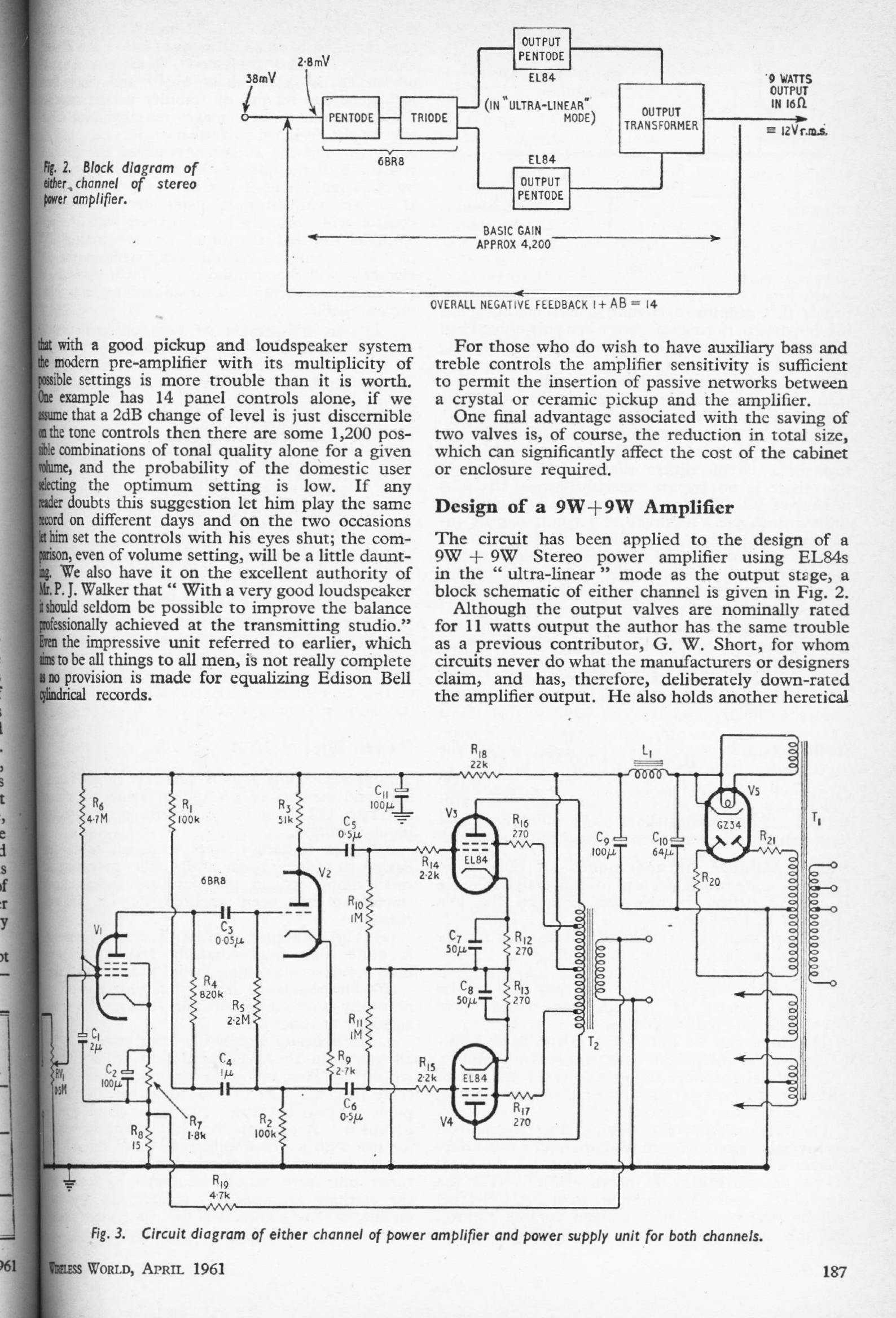
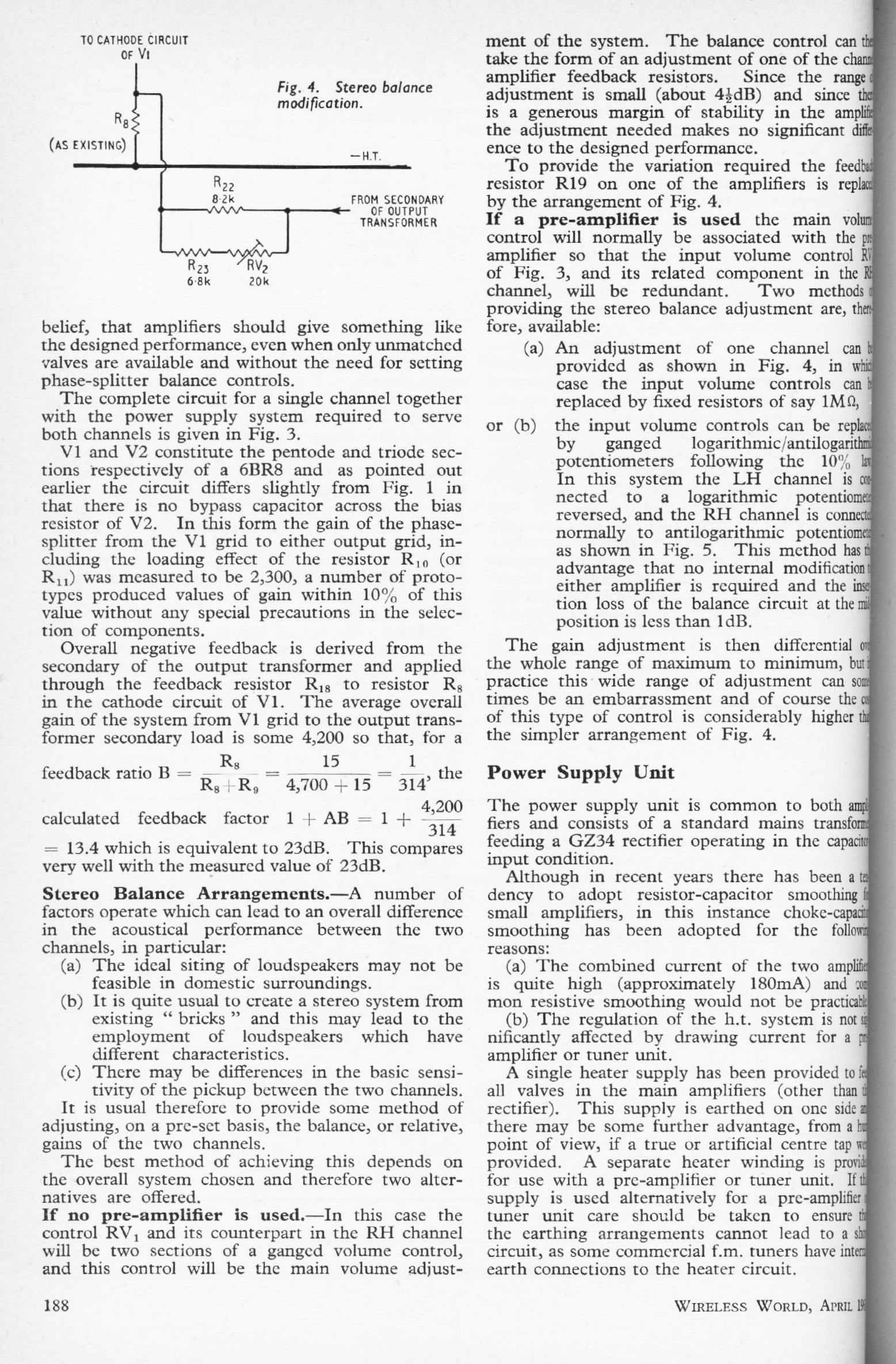
LOW-COST STEREO AMPLIFIER Part 1: Apr 1961
E Jeffery
Two-parter describing a 9W + 9W stereo valve power amplifier
|
|
|
| ||||||
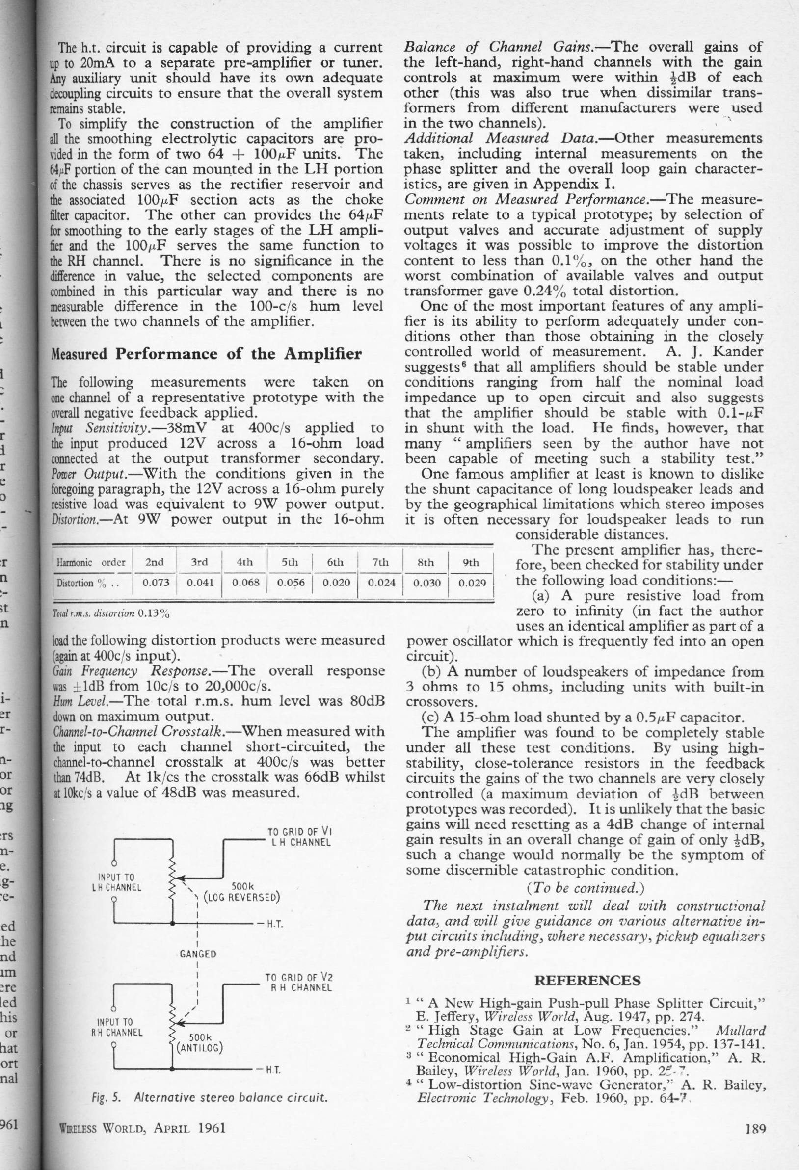
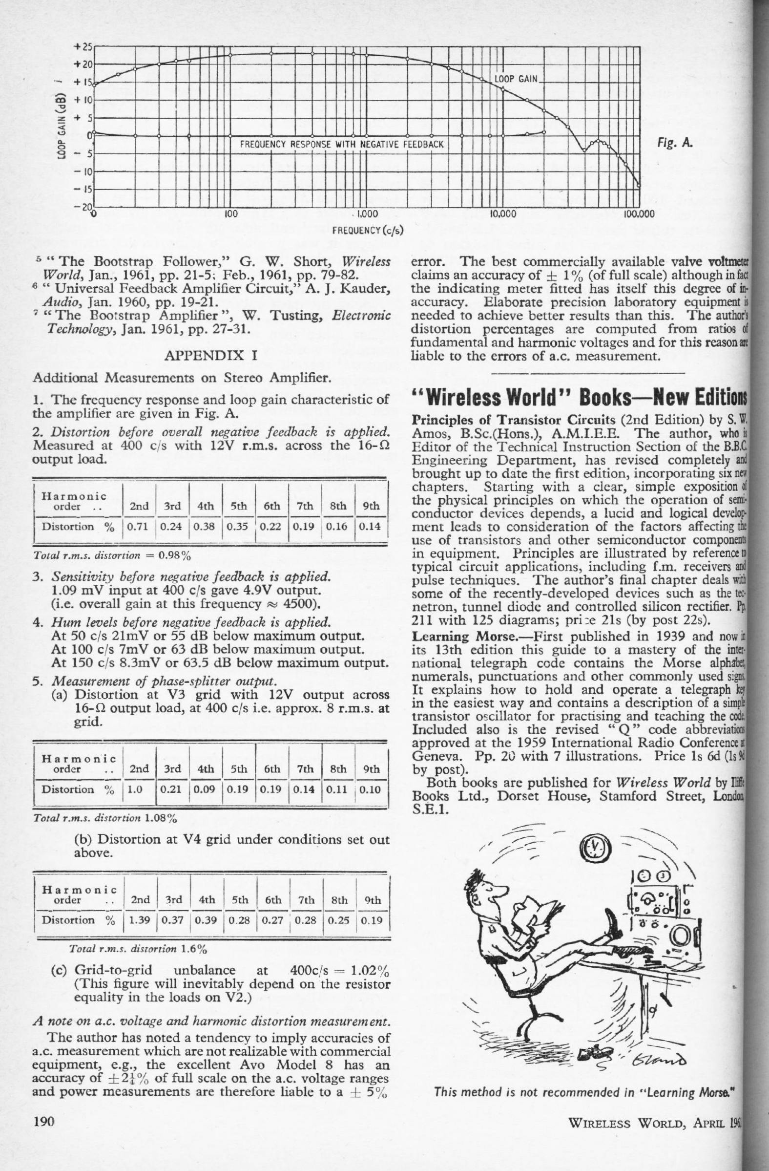
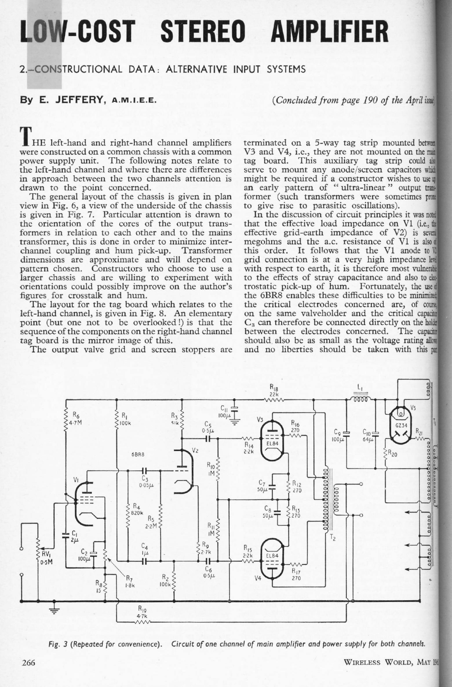
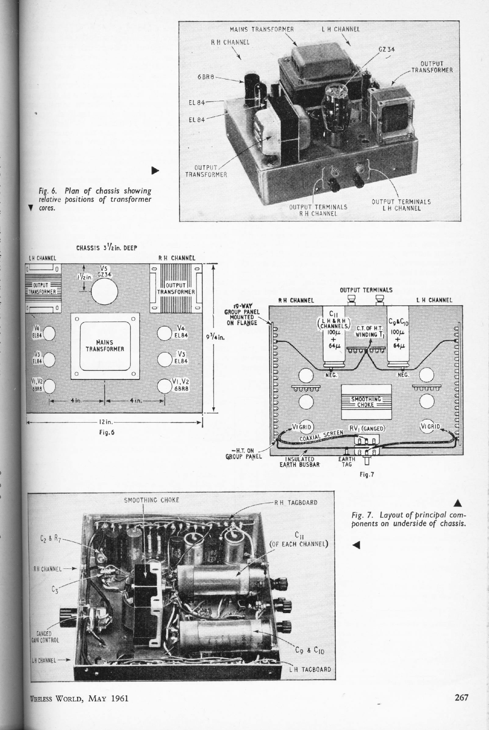
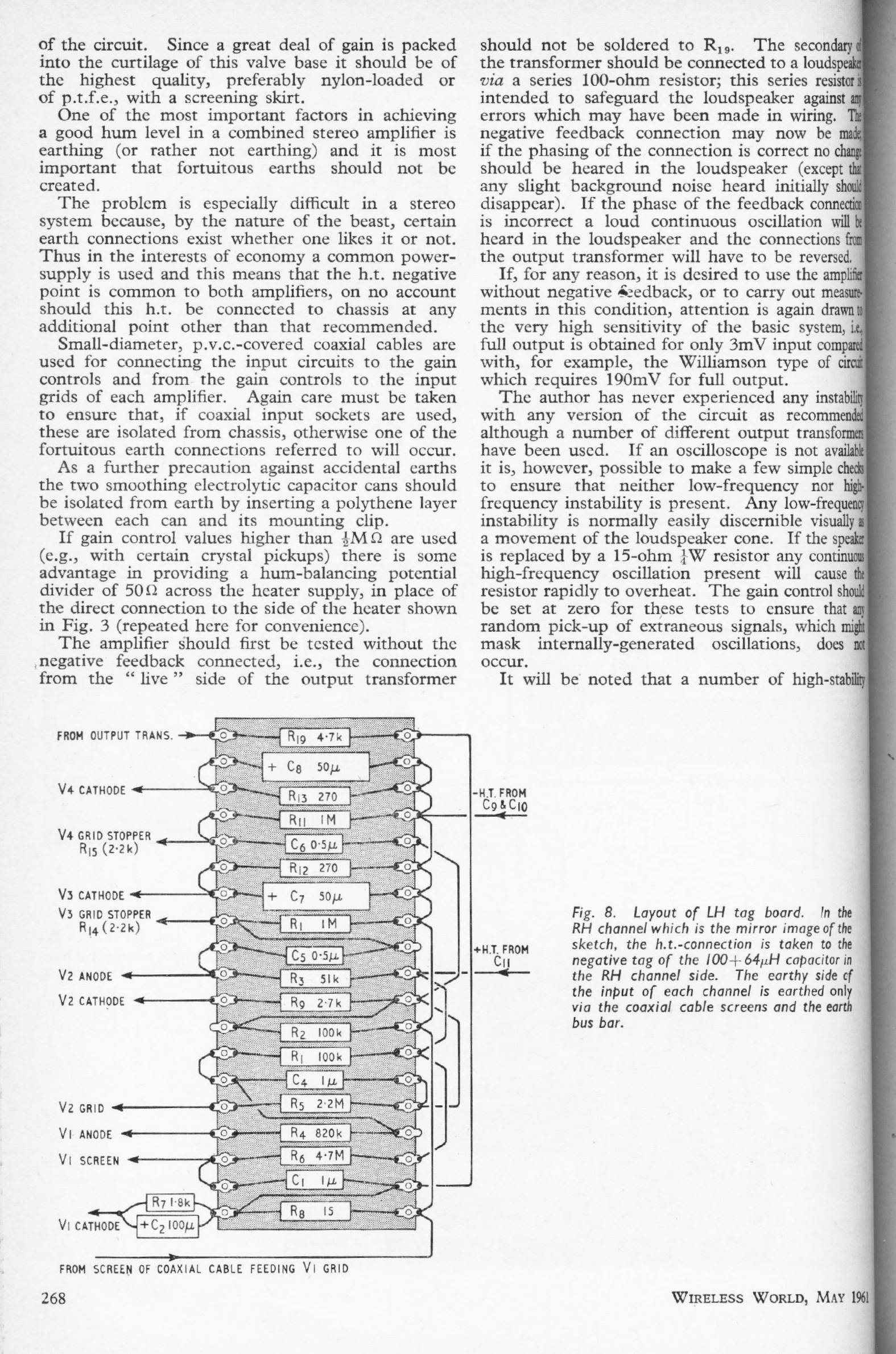
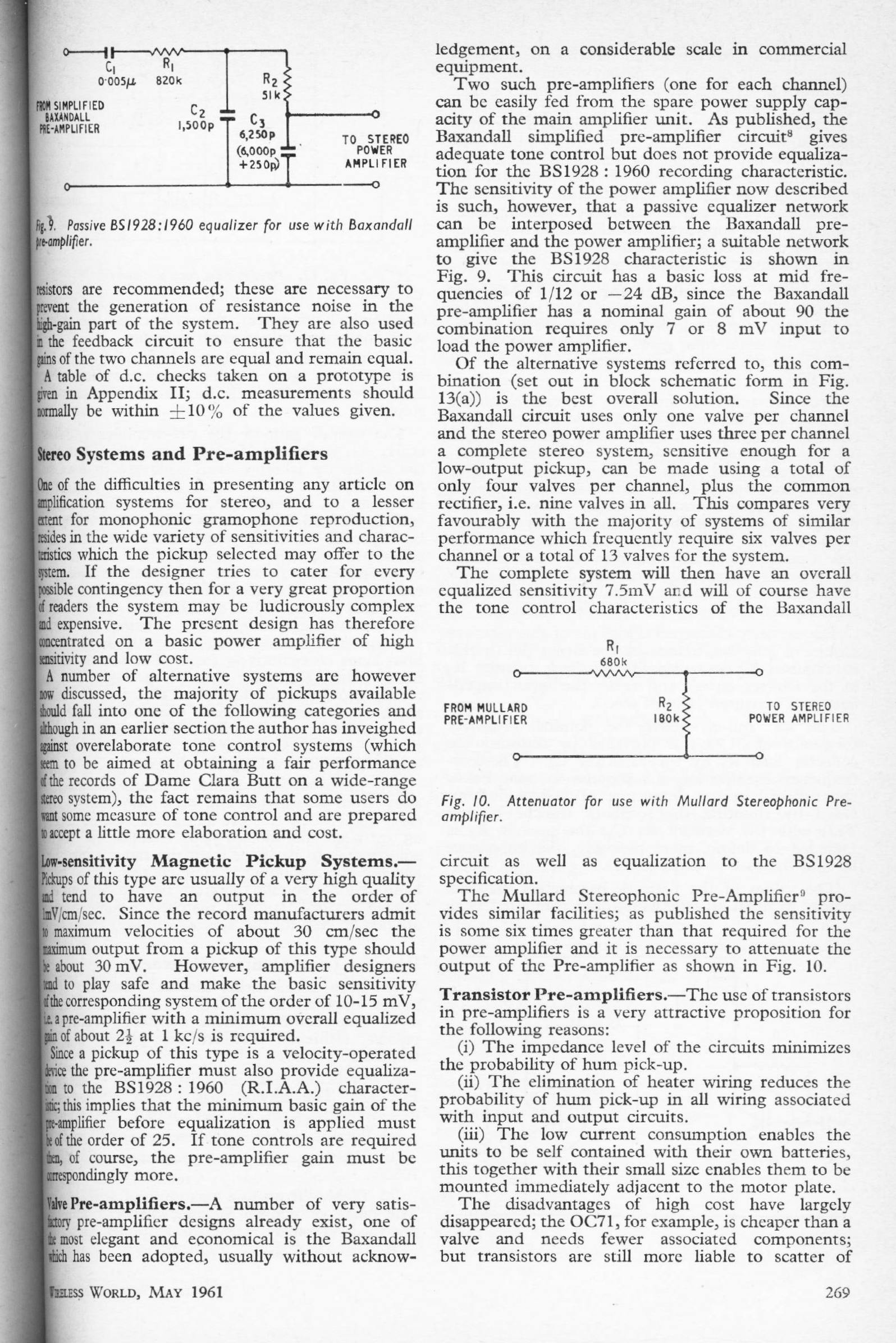
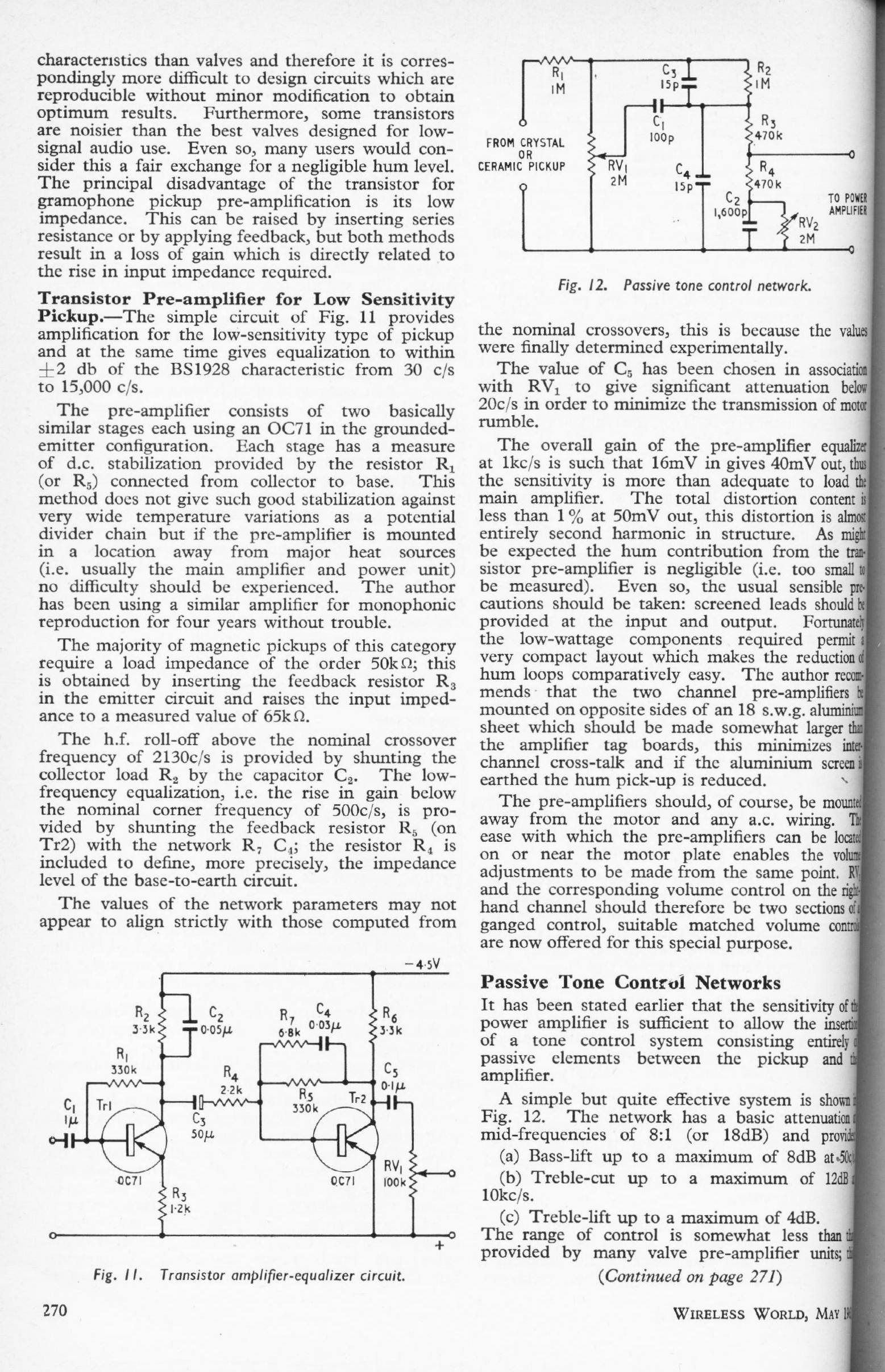
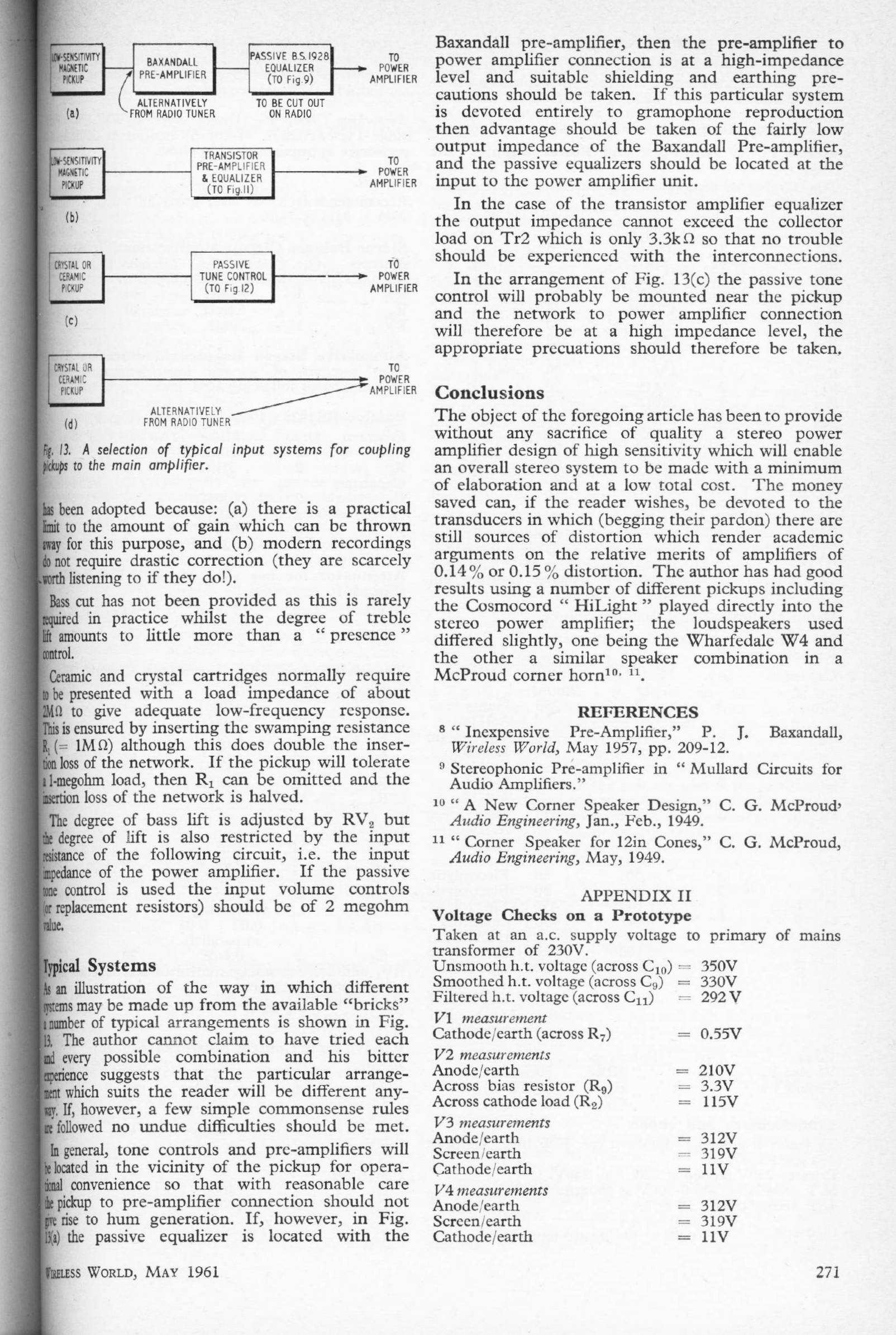
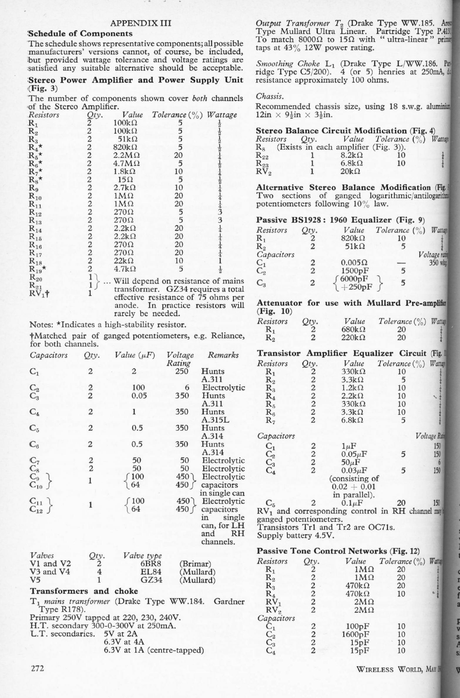
LOW-COST STEREO AMPLIFIER Part 2: May 1961
E Jeffery
Two-parter describing a 9W + 9W stereo valve power amplifier
|
|
|
| The second part of this power amplifier article discusses the practical construction in pitiless detail, including wiring diagrams and very comprehensive parts lists. Note that even at this late date there is discussion of passive equalisation and passive tone-control circuits. | ||||||
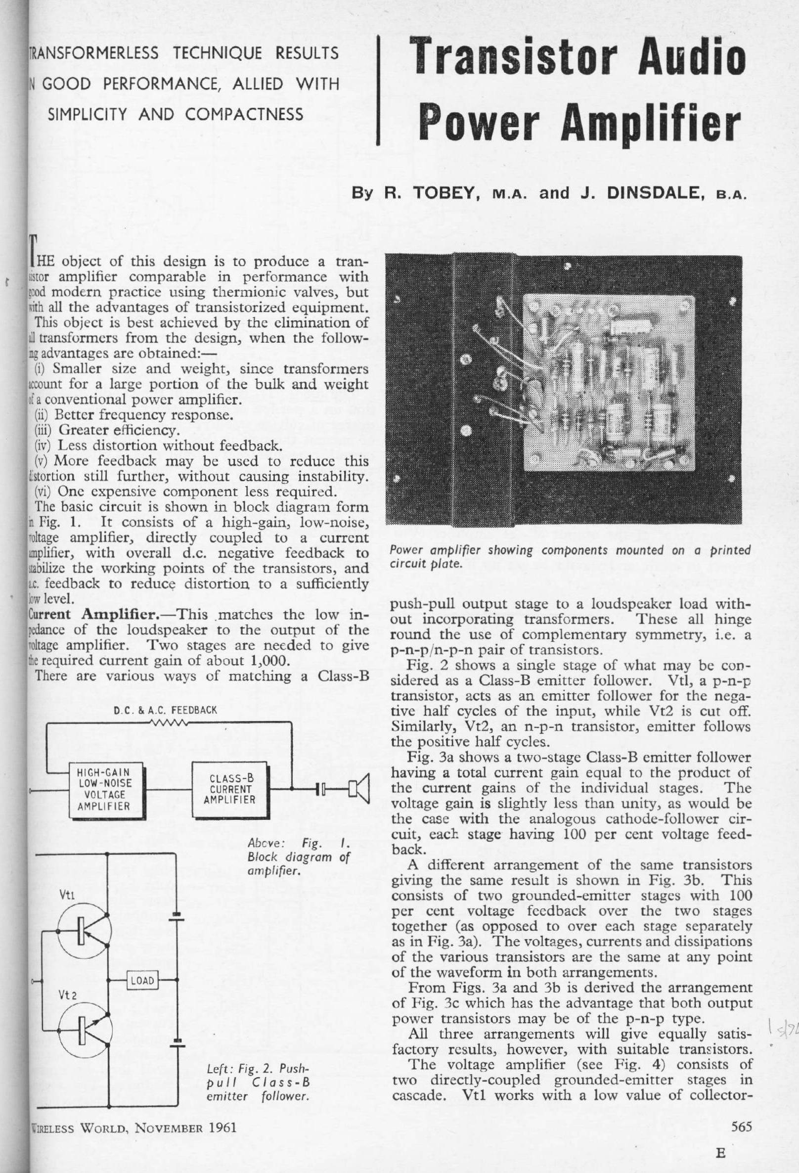
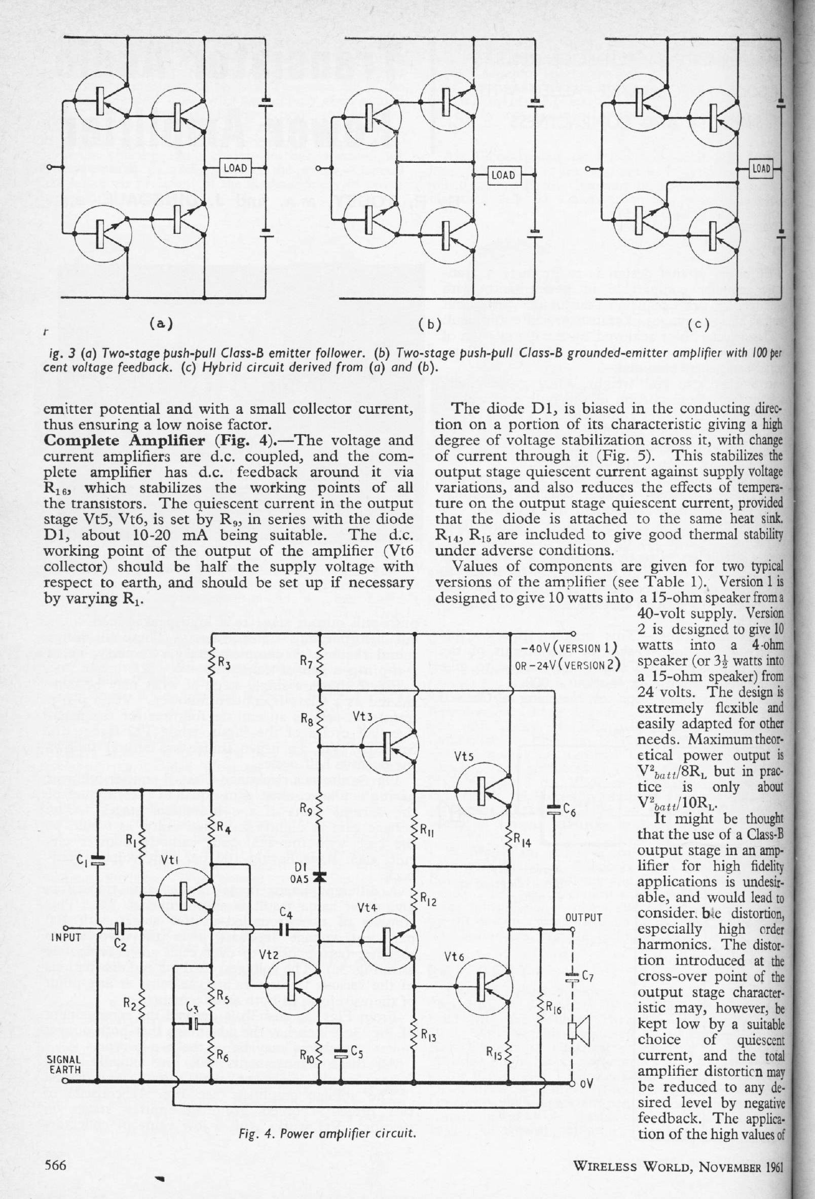
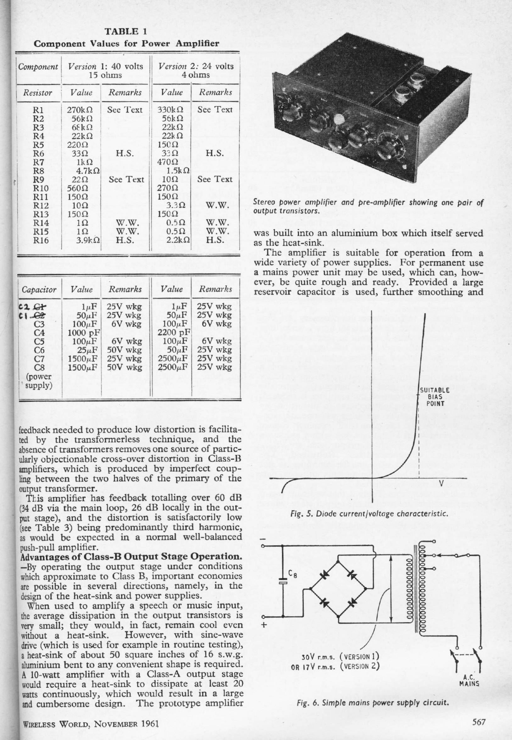
TRANSISTOR AUDIO POWER AMPLIFIER: Nov 1961
R Tobey & J Dinsdale
This article is one of the milestones of power amplifier design in WW. It is one of the first designs to look like what we would call a modern power amplifier.
|
|
|
| ||||||
TRANSISTOR HIGH-FIDELITY PRE-AMPLIFIER: Dec 1961
R Tobey & J Dinsdale
A preamplifier designed by Tobey & Dinsdale to complement their power amplifier of November 1961.
|
|
| To the modern eye this looks like a very minimalist design. The single-transistor first stage implements a shunt-feedback phono stage, with alternative switched feedback networks for auxiliary (line) and microphone inputs. The RIAA equalisation is partly implemented by using the cartridge inductance in conjunction with a resistive load, and this of course means that it can only be accurate for one value of inductance; change the cartridge type and you will have to re-design the input networks. Not good. The second stage is a Baxandall tone-control stage, arranged so the response rolls off below 50 Hz when large amounts of bass boost are used, and it also implements a relatively sophisticated low-pass 'scratch' filter with three switched frequencies, though this shows some undesirable peaking before roll-off.A signal to noise ratio of 70 dB with the tone controls flat is quoted, which by today's standards is unimpressive; the input used is not stated. No information on the distortion performance of the preamplifier alone is given, but with the very limited amount of open-loop gain available, it is clearly going to be poor. A figure of 0.45% (at 10W) is quoted for a complete system of preamp and T & D power amp. Ouch... | ||||||
SLIDING-BIAS AMPLIFIERS: May 1962 NEW
Thomas Roddam
Sliding-bias operation uses a Class-A amplifier with a quiescent current that is controlled by the signal amplitude so that it increases when the output level is high, and falls back when it is low, to save power. The control signal is derived by peak-rectifying the input signal. This can obviously only operate in "oops- sorry" mode; in other words the start of every transient will be mangled as it takes a finite time for the quiescent current to be increased.
|
| |||||||
Quite why Mr Roddam thought this technology, which he explains is already old, (it is believed to have originated with Mullard) was a better plan than Class-B is obscure. Class-B was well known at the time. | ||||||||
"UNBIASED": Oct 1963
by Free Grid
"Unbiased" was a commentary that appeared in Wireless World every month for almost 34 years.
It was written by 'Free Grid', the pseudonym of Norman Preston Vincer-Minter (?? - 1964). While the articles were often interesting, Free Grid had an unfortunate tendency to get bogged down in tedious etymological pedantry, as in the first section of this example.
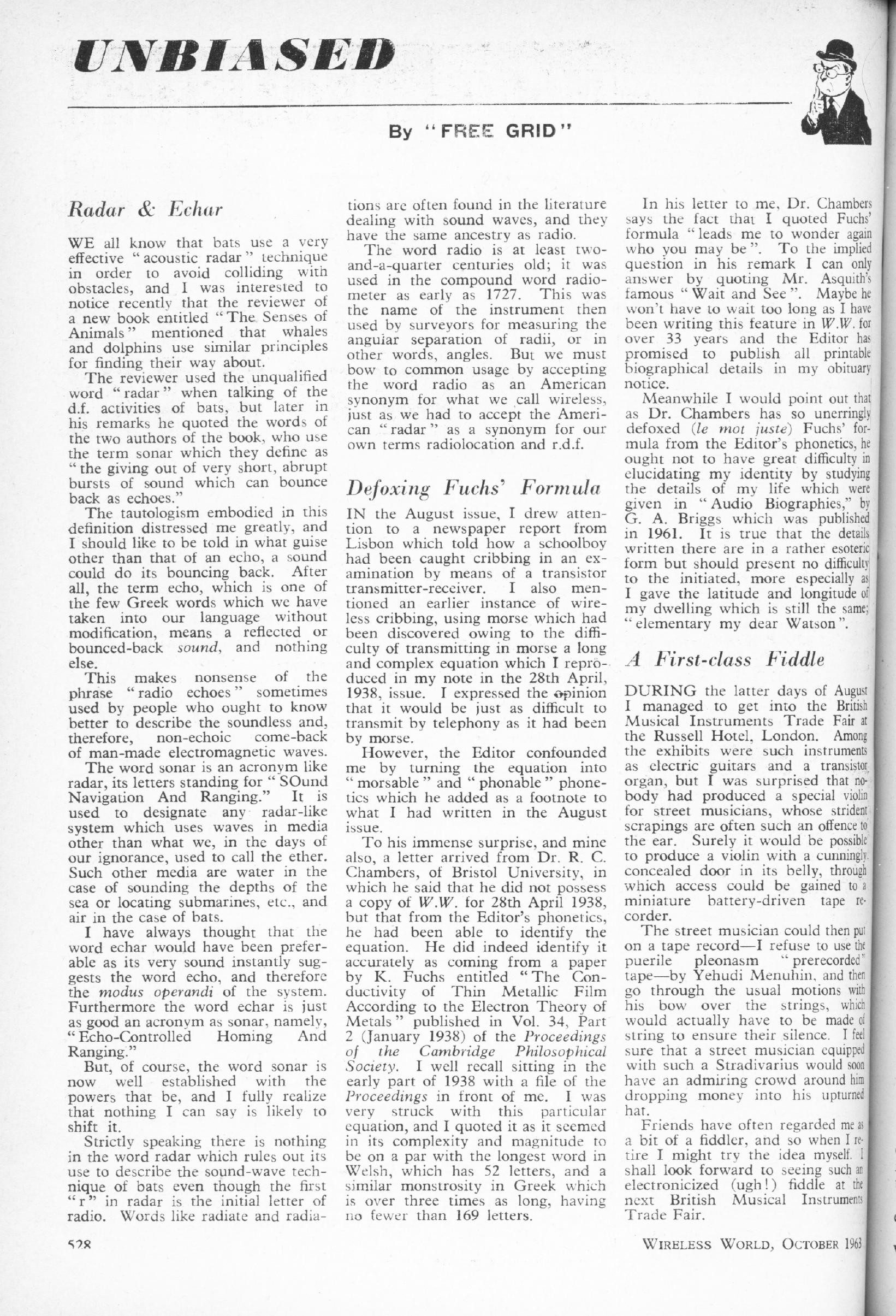
| While this is in many ways a typical contribution, what caught my eye was the reference to Klaus Fuchs in the second section, where an equation from one of his scientific papers was used as an example. Klaus Fuchs is far better known for having been one of the most notorious and damaging cold war spies; he was convicted in 1950. Surely both Free Grid and the Editor of WW would have realised who they were referring to? The cold war was very much still going on in 1963.Was Free Grid's choice of Fuchs' equation some sort of elaborate joke? I suspect so. |
![]()
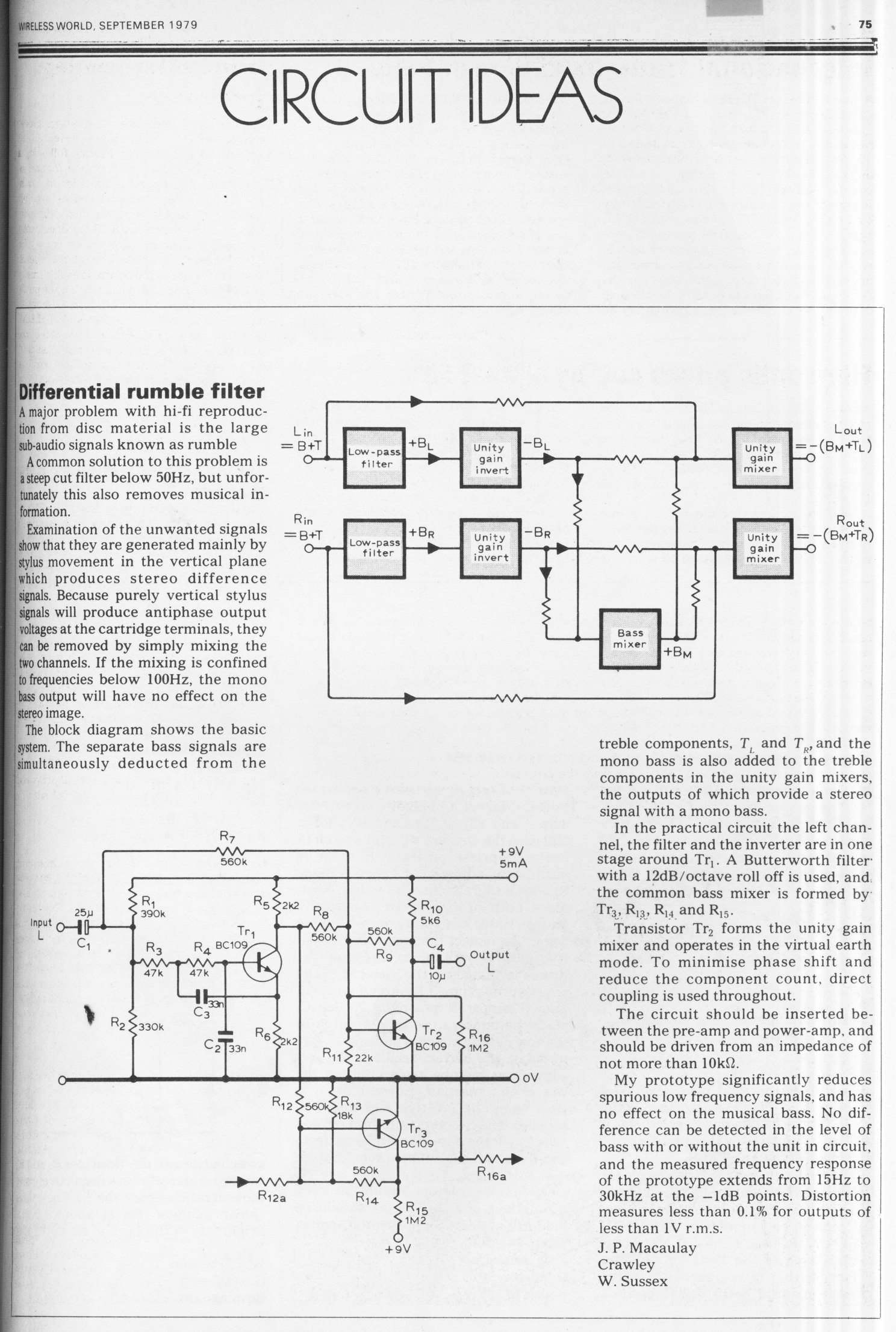
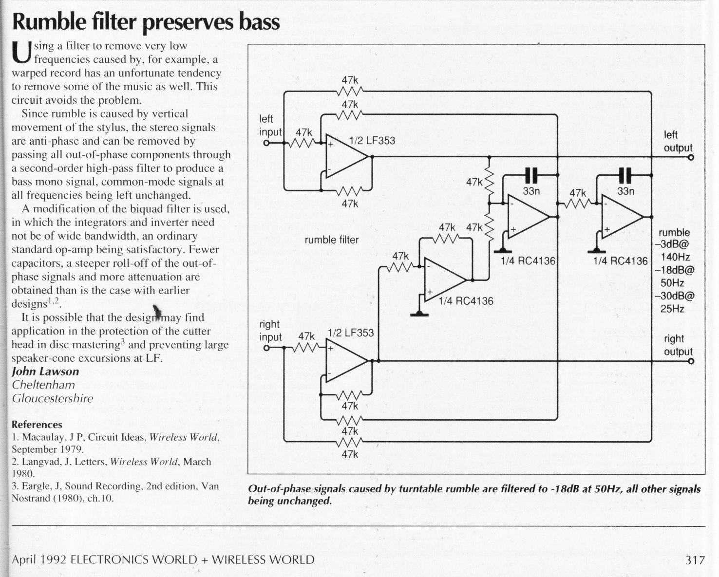
RUMBLE CROSSFEED FILTERS
|

|