Updated: 25 Sept 2001


Thermal Distortion in a Power Amp IC. |
Updated: 25 Sept 2001
 
|
Thermal non-linearities would presumably appear as second or third harmonic distortion rising at low frequencies, and the largest effects should be in Class-B output stages where dissipation varies greatly over a cycle. There is absolutely no such effect to be seen in discrete-component power amplifiers.

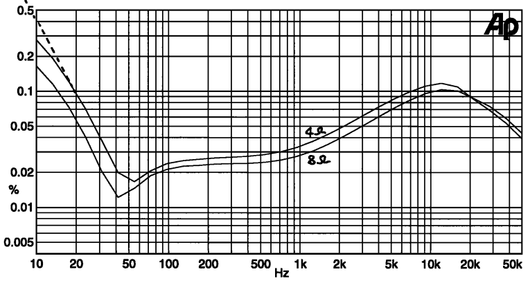
Above: distortion plot for the Phillips TDA1522Q IC. Power out was 4.4W rms into 8 Ohms, 8W rms into 4 Ohms.
BUT thermal distortion certainly does exist in IC power amplifiers. Above is a distortion plot for the Phillips TDA1522Q power amp IC, which I believe shows the effect. The power level was 4.4W into 8 Ohms, 8W into 4 Ohms. As is usual for such amplifiers, the distortion is generally high, but drops into a notch at 40 Hz; the only feasible explanation for this is cancellation of distortion products from two separate distortion sources. At frequencies below this notch there is second-harmonic distortion rising at 12dB/octave as frequency falls. The LF residual looks quite different from the midband distortion, which was a mixture of second and third harmonic plus crossover spikes.
All other possible sources of an LF distortion rise, such as inadequate decoupling, were excluded. There was no output capacitor to introduce nonlinearity.
It seems pretty clear that the steep rise here is due to thermal distortion, in the form of feedback from the power output stage to earlier parts of the amplifier- probably the input stage. As would be expected, the effect is greater with a heavier load which causes more heating; in fact halving the load doubles the THD reading below the 40 Hz notch.
The dotted line shows a 12dB/octave slope.
The THD figure falls above 10 kHz because of the 80 kHz bandwidth limitation on the residual, and the high-order nature of the harmonics that make up crossover distortion.


