A similar situation can occur when water-pipes are connected to
"mains ground" except that interference is not usually by a
common ground impedance; however the unwanted currents flowing in
the pipework generate magnetic fields that may either create ground
loops by induction, or interfere directly with equipment such as
mixing consoles. In practice ground voltages cause a far greater number of
noise problems than the other mechanisms.
Even if there is no common-impedance coupling (for example,
if the balanced line is fully floating and not galvanically
connected to ground- this is only possible with a transformer-
to-transformer connection) ground currents may still enter the
signal circuit by transformer action. The shield wire or foil
acts as a transformer primary while the signal lines act as
secondaries; if the magnetic field from the shield wire is not
exactly uniform then a differential noise voltage appears
across the signal pair and is amplified as if it were a
genuine signal. This effect is often called Shield-Current-
Induced-Noise (SCIN), and cables vary in their susceptibility
to it according to the details of their construction. [4] It
is fortunate that the level of this effect is below the noise-
floor in most circumstances and with most cables, for once a
differential-mode signal has been induced in the signal lines,
there is no way to discriminate against it.
There are thus two principle effects to guard against;
electrostatic coupling, and the intrusion of unwanted
voltages from either magnetic coupling or ground-loop
currents.
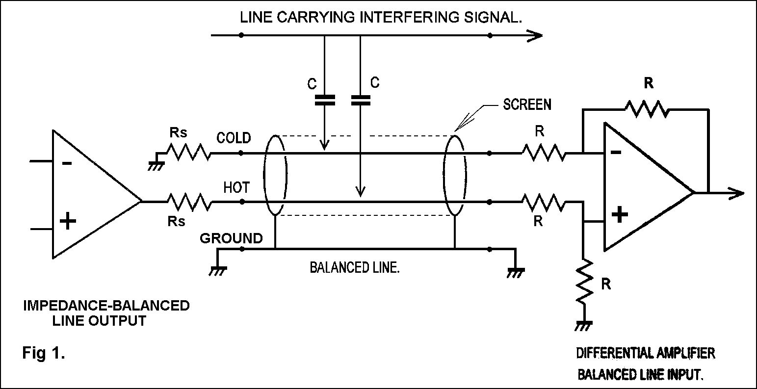
Electrostatic interference can be represented by notional
current-sources connected to both signal lines; these will
only be effectively cancelled if the line impedances to ground
are the same, as well as the basic CMRR being high. The likely
levels of electrostatic interference current in practice are
difficult to guess at, so the figures I give here are
calculated from applying 1 mA to each line; this would be very
severe crosstalk, but it does allow convenient relative
judgements to be made.
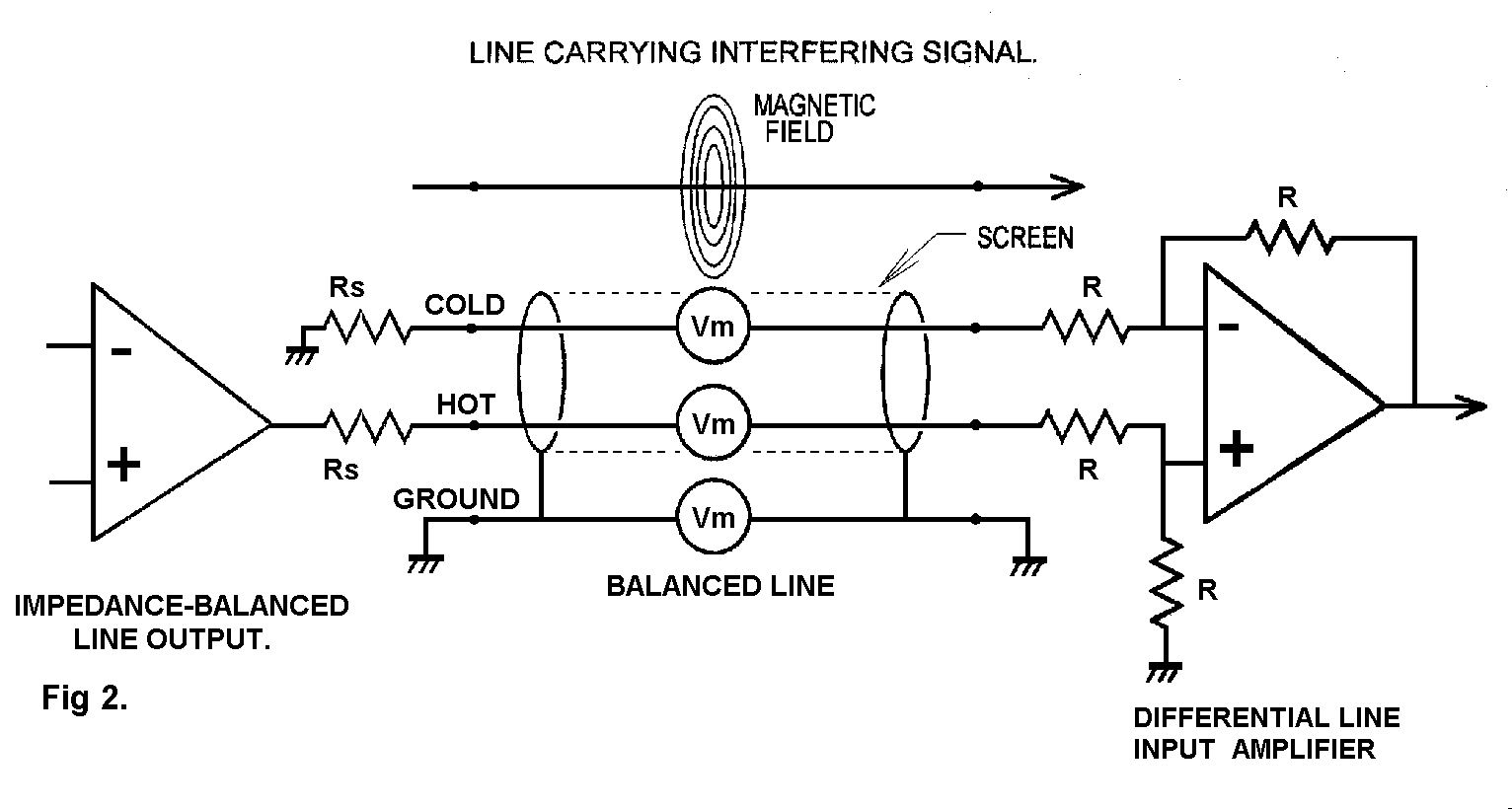
Magnetic and ground-voltage interference can be represented
by notional voltage-sources inserted in both signal lines and
the ground wire; these are not line-impedance sensitive and
their rejection depends only on the basic CMRR, as measured
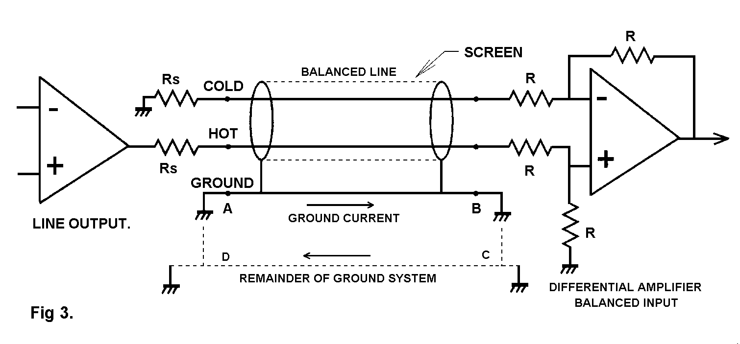
with low-impedance drive to each input. Similarily ground-
voltage interference can be represented by a voltage-source in
the ground wire only. Both input and output are voltages so
the CMRR can be quoted simply as a ratio in dB, without
specifying any level.
4: LINE OUTPUTS.
A line output is expected to be able to drive significant
loads, partly because of a purely historical requirement to
drive 600 Ohms, and partly to allow the parallel feed of
several destinations. Another requirement is a low source
impedance, (100 Ohms or less) to make the signal robust
against capacitive crosstalk etc.
There are many line output and input arrangements possible,
and the results of the various permutations of connection are
not always entirely obvious. An examination of the output
types in use yields Table 1:
TABLE 1: Output arrangements.
- Unbalanced output.
- Impedance-balanced output.
- Ground-cancelling output. (or ground-compensated output)
- Balanced output.
- Quasi-floating output.
- True floating transformer output.
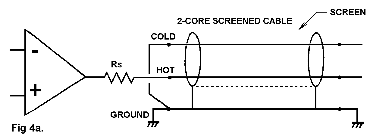
1) Unbalanced output. See Fig 4a.
There are only two physical output terminals- signal and
ground. A third terminal is implied in Fig 4a, emphasising
that it is always possible to connect the cold wire in the
cable to the ground at the transmitting (output) end. The
output amplifier is almost always buffered from the line
shunt-capacitance by a resistor Rs in the range 33 - 100 Ohms,
to ensure stability, and this unbalances the line impedances.
If the output resistance is taken as 100 Ohms worst-case, and
the cold line is simply grounded as in Fig 4a, then the
presence of Rs degrades the CMRR to -46 dB even if the
balanced input at the other end of the cable has perfectly
matched resistors.
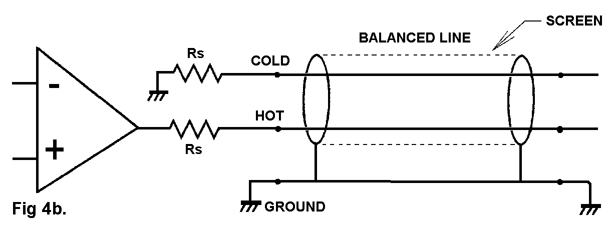
2) Impedance balanced output. See Fig 4b
There are now three physical terminals, hot, cold, and
ground. The cold terminal is neither an input nor an output,
but a resistive termination with the same resistance Rs as the
hot terminal output impedance. This type of output is intended
for use with receiving equipment having balanced inputs, and
the presence of the second Rs terminated to output ground
makes the impedance on each signal line almost exactly the
same, (apart from op-amp output impedance limitations) so that
good rejection is achieved for both common-mode ground
voltages and electrostatic interference.
If an unbalanced input is being driven, the cold terminal
on the transmitting (output) equipment can be either shorted
to ground locally or left open-circuit without serious
consequences, though either way all the benefits of balancing
are lost.
The use of the word "balanced" is unfortunate as this
implies anti-phase outputs, which are not present.
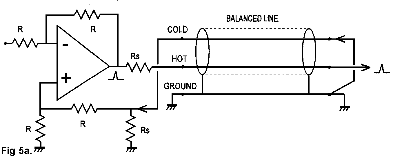
3) Ground-cancelling output. (also called a ground-compensated
output) See Fig 5a.
This method allows ground voltages to be cancelled out even if the
receiving equipment has an unbalanced input. It prevents any
possibility of creating a phase error by miswiring. It
separates the wanted signal from the unwanted by addition at
the output end of the link, rather than by subtraction at the
input end. If the receiving equipment ground differs in
voltage from the sending ground, then this difference is added
to the output so that the signal reaching the receiving
equipment has the same voltage superimposed upon it. Input and
ground therefore move together and there is no net input
signal, subject to the usual CMRR tolerances.
The cold pin of the output socket is now an input, and must
have a unity-gain path summing into the main signal output
going to the hot output pin. It usually has a very low input
impedance equal to the hot terminal output impedance.
It is unfamiliar to most people to have the cold pin of an
output socket as a low impedance input, and this can cause
problems. Shorting it locally to ground merely converts the
output to a standard unbalanced type. If the cold input is
left unconnected then there should be only a very small
degradation of noise due to the very low input impedance of
Rs.
Ground-cancelling outputs are an economical way of making
ground-loops innocuous.
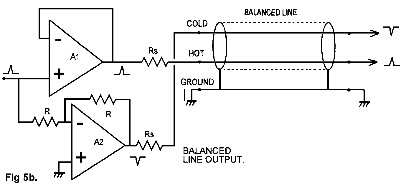
4) Balanced output. See Fig 5b.
The cold terminal is now an active output, producing the
same signal as the hot terminal but phase-inverted. This can
be simply done by using an op-amp stage with a gain of minus
one to invert the normal in-phase output. Phase spikes are
shown on the diagram to emphasise these phase relationships.
The in-phase signal itself is not degraded by passing
through an extra stage and this can be important in quality-
critical designs. The inverting output must not be grounded;
if not required it can simply be ignored. Unlike quasi-
floating outputs, it is not necessary to ground the cold pin
to get the correct gain for unbalanced operation, and it must
not be grounded by mistake, because the inverting op-amp will
then spend most of its time in current-limiting, probably
injecting unpleasant distortion into the preamp grounding
system, and possibly suffering unreliability. Both hot and
cold outputs must have the same output impedance Rs to keep
the line impedances balanced.
A balanced output has the advantage that it is unlikely to
crosstalk to other lines even if they are unbalanced, as the
current injected via the stray capacitance from each
crosstalking line will cancel at the receiving end. Another
advantage is that the total signal level on the line is
increased by 6 dB, which can be valuable in difficult noise
situations. All balanced outputs give the facility of
correcting phase errors by deliberately swopping hot and cold
outputs. This tactic is however a two-edged sword, because it
is probably how the phase became wrong in the first place.
This form of balanced output is the norm in hi-fi balanced
interconnection, but is less common in professional audio,
where the quasi-floating output gives more flexibility.
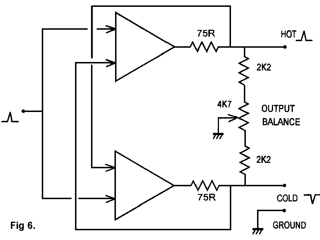
5) Quasi-floating output. See Fig 6.
This kind of output approximately simulates a floating
transformer winding; if both hot and cold outputs are driving
signal lines, then the outputs are balanced, as if a centre-
tapped output transformer were being used. If, however, the
cold output is grounded, the hot output doubles in amplitude
so the total level is unchanged. This condition is detected by
the current-sensing feedback taken from the outside of the 75R
output resistors, and the current driven into the shorted cold
output is automatically reduced to a low level that will not
cause problems.
Similarly, if the hot output is grounded, the cold output
doubles in amplitude and remains out of phase; the total hot-
cold signal level is once more unchanged. This system has the
advantage that it can give the same level into either a
balanced or unbalanced input without rewiring connectors. 6 dB
of headroom is however lost.
When an unbalanced output is being driven, the quasi-
floating output can be wired to work as a ground-cancelling
connection, with rejection of ground noise no less effective
than the true balanced mode. This requires the cold output to
be grounded at the remote (input) end of the cable. Under
adverse conditions this might cause HF instability, but in
general the approach is sound. If you are using exceptionally
long cable, then it is wise to check that all is well.
If the cold output is grounded locally, ie at the sending
end of the cable, then it works as a simple unbalanced output,
with no noise rejection. When a quasi-floating output is used
unbalanced, the cold leg must be grounded, or common-mode
noise will degrade the noise floor by at least 10 dB, and
there may be other problems.
In both of the unbalanced cases the maximum signal possible
on the line is reduced by 6 dB.
Quasi-floating outputs use a rather subtle circuit with an
intimate mixture of positive and negative feedback of current
and voltage. This performs the required function admirably;
its only drawback is a tendency to accentuate circuit
tolerances, and so a preset resistor is normally required to
set the outputs for equal amplitude; the usual arrangement is
shown in Fig 6. If the balance preset is not correctly
adjusted one side of the output will clip before the other and
reduce the total output headroom. After factory setting this
preset should not need to be touched unless the resistors in
the circuit are replaced; changing the opamp should make no
difference. The balancing network consists of a loading
resistor to ground on each output; in this respect the output
characteristics diverge from a true floating output, which
would be completely isolated from ground. These loading
resistors are lower than the input impedance of typical
balanced inputs, so if simple differential amplifiers are used
with unequal input impedances, (see the section on line
inputs, below) the output balance is not significantly
disturbed and clipping remains symmetrical on the hot and cold
outputs.
Quasi-floating outputs are often simply referred to as
"balanced" or "electronically-balanced", but this risks
serious confusion as the true balanced output described in 4)
above must be handled in a completely different way from
quasi-floating.
6) True floating transformer output.
This can only be implemented with a transformer if galvanic
isolation from ground is required. The technique is rarely
used, because of the cost, weight, and performance problems of transformers, but is sometimes found in touring PA systems (usually only in the mic-splitter box on the stage) and broadcast environments where enormous RF field strengths are encountered.
5: LINE INPUTS.
There are only two kinds of input stage- unbalanced and
balanced. For interconnection this is the primary distinction.
Apart from balancing requirements, a line-level input, as
opposed to a microphone input, is expected to have a
reasonably high impedance to allow multiple connections to a
single output. Traditionally a "bridging impedance"- ie high
enough to put negligible loading on historical 600 Ohm lines-
was 10K minimum, and this is still appropriate for modern low-
impedance outputs. However, a higher impedance of 100K or even
more is desirable for interfacing to obsolete valve equipment,
to avoid increased distortion and curtailed headroom.
Another common requirement is true variable gain at the
balanced input, as putting the gain control further down the
signal path means that it is impossible to prevent input
amplifier overload. Thus we need a balanced stage that can
attenuate as well as amplify, and this is where the circuit
design starts to get interesting. In the following circuitry,
small capacitors often shunt the feedback elements to define
bandwidth or ensure stability. These are omitted for clarity.
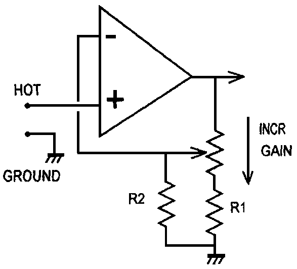
1) Unbalanced inputs.
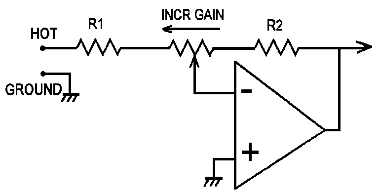
These are straightforward; variable-gain series-feedback
stages are easily configured as in Fig 7, providing a minimum
gain of unity is acceptable; R2 sets the gain law in the
middle of the pot travel. It is also simple to make a stage
that will attenuate as well as amplify, but this implies a
shunt-feedback configuration as in Fig 8, with a variable
input impedance. The minimum input impedance R1 cannot be much
higher than 10k or resistor noise becomes excessive.
For a series-feedback stage, the input impedance can be
made as high as desired by bootstrapping; an input resistance
of 500k or greater is perfectly possible, and does not imply a
poorer noise performance, as this depends on the source
resistance and semiconductor characteristics. To ram the point
home, my own personal best is 1 GOhm, in a capacitor
microphone head amplifier. Although the input impedance is
many orders of magnitude greater than the 1 to 2 k of a
dynamic mic preamp, the EIN is -110 dBu, ie only 18 dB worse.
Naturally, any unbalanced input can be made balanced or
floating by adding a transformer.
2) Balanced inputs.
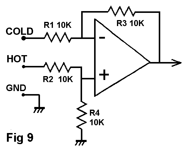
A standard one-op-amp differential input stage is shown in
Fig 9. Unlike instrumentation work, a super-high CMRR is
usually unnecessary. Ordinary 1% resistors and no trimming
will not give CMRR better than 45 dB; however this is usually
adequate for even high-quality audio work.
It is never acceptable to leave either input floating, as
this will cause serious deterioration of noise, hum etc.
Grounding the cold input locally to create an unbalanced input
is quite alright, though naturally all the balanced noise
rejection is lost. The hot input can be locally grounded
instead, and the cold input driven, to create a phase-
inverting input that will correct a phase error elsewhere, but
this is not good practice- the right thing to do is to sort
out the original phase error.
BALANCED INPUT TECHNOLOGIES.
There are many, many ways to make balanced or differential
input amplifiers, and only the most important in audio are
considered. These are:
TABLE 2.
| 1) | The standard differential amplifier. | Fig 9
|
| 2) | Switched-gain balanced amp. | Fig 10
|
| 3) | Variable-gain balanced amp. | Fig 11
|
| 4) | The "Superbal" amp. | Fig 12
|
| 5) | Hi-Z balanced amp. | Fig 13
|
| 6) | Microphone preamp plus attenuator | Fig 14
|
| 7) | Instrumentation amp. |
|
1) The standard one-opamp differential amplifier is a very
familiar circuit block, but its operation often appears
somewhat mysterious. The version in Fig 9 has a gain of R3/R1.
(=R4/R2) It appears to present inherently unequal input
impedances to the line; this has often been commented on, [5]
and some confusion has resulted. The root of the problem is
that a simple differential amplifier has interaction between
the two inputs, so that the input impedance on the cold input
depends strongly on the signal applied to the hot input. Since
the only way to measure input impedance is to apply a signal
and see how much current flows into the input, it follows that
the apparent input impedance on each leg varies according to
the way the inputs are driven. If the amplifier is made with
four 10K resistors, then the input impedances Z are:
TABLE 3: Differential amplifier input impedances.
| Case| HOT i/p Z | COLD i/p Z
| | 1. | Hot only driven | 20k | Grounded
| | 2. | Cold only driven | Grounded | 10k
| | 3. | Both driven balanced | 20k | 6.7k
| | 4. | Both driven CM, ie together | 20k | 20k
| | 5. | Both driven floating | 10k | 10k
| |
Some of these impedances are not exactly what you would
expect. In Case 3, where the input is driven as from a
transformer with its centre-tap grounded, the unequal input
impedances are often claimed to "unbalance the line". However,
since it is common-mode interference we are trying to reject,
the CM impedance is what counts, and this is the same for both
inputs. The vital point is that the line output amplifier will
have output impedances of 100 Ohms or less, completely
dominating the line impedance. These input impedance
imbalances are therefore of little significance in practice;
audio connections are not transmission lines (unless they are
telephone circuits several miles long) so the input impedances
do not have to provide a matched and balanced termination.
The low impedance of 6.7k on the cold input sounds
impossible as the first thing the signal encounters is a 10k
series resistor, but the crucial point is that the hot input
is driven simultaneously, so the inverting op-amp input is
moving in the opposite direction to the cold input, due to
negative feedback, a sort of anti-bootstrapping that reduces
the effective value of the 10k resistor to 6.7k. The input
impedances in this mode can be made equal by manipulating
resistor values, but this makes the CM impedances (to ground)
unequal, which seems more undesirable.
In Case 5, where the input is driven as from a floating
transformer with any centre-tap unconnected, the impedances
are nice and equal; they must be, because with a floating
winding the same current must flow into each input. However,
in this connection the line voltages are not equal and
opposite: with a true floating transformer winding the hot
input has all the signal voltage on it while the cold has none
at all, due to the internal coupling of the balanced input
amplifier. This seemed very strange when it emerged from
simulation, but a reality-check proved it true. The line has
been completely unbalanced as regards talking to other lines,
although its own common-mode rejection remains good.
Even if perfectly matched resistors are assumed, the CMRR
of this stage is not infinite; with a TL072 it is about -90
dB, degrading from 100 Hz upwards, due to the limited open-
loop gain of the opamp.
2: The need for a balanced input stage with two switched gains
crops up frequently. The classic application is a mixing desk
to give optimum performance with both semi-pro (-7.8 dBu) and
professional (+4 dBu) interface levels. Since the nominal
internal level of a mixer is usually in the range -4 to 0 dBu,
the stage must be able to switch between amplifying and
attenuating, maintaining good CMRR in both modes.
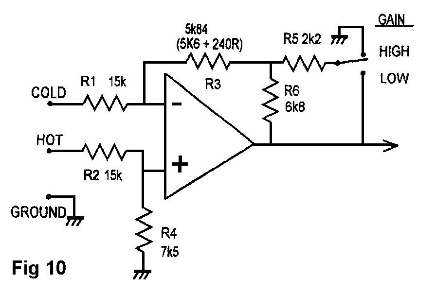
The obvious way to change gain is to switch both R3,R4 in
Fig 9, but a neater technique is shown in Fig 10. Perhaps
surprisingly, the gain of a differential amplifier can be
manipulating by changing the drive to the feedback arm (R3
etc) only, without affecting the CMRR. The vital point is to
keep the resistance of this arm the same, but drive it from a
scaled version of the opamp output. Fig 10 uses the network
R5,R6, which has the same 2k output impedance whether R4 is
switched to the output (low gain) or ground (high gain). For
low gain the feedback is not attenuated, but fed through R5,R6
in parallel. For high gain R5,R6 become a potential divider.
R3 is reduced by 2k to allow for the R5,R6 output impedance.
The stage can attenuate as well as amplify if R1 is greater
than R3, as shown here. The nominal output of the stage is
assumed to be -2 dBu; the two gains are -6.0 and +6.2 dB.
The differential input impedance is 11.25k via the cold and
22.5k via the hot input. Common mode input impedance is 22.5k
for both inputs.
3: A variable-gain balanced input should have its gain control
at the very first stage, so overload can always be avoided.
Unfortunately, making a variable-gain differential stage is
not so easy; dual pots can be used to vary two of the
resistances, but this is clumsy and will give shocking CMRR
due to pot mismatching. For a stereo input the resulting 4-
gang pot is unattractive.
The gain-control principle is essentially the same as for
the switched-gain amplifier above. To the best of my knowledge
I invented both stages in the late 70s, but so often you
eventually find out that you have re-invented instead; any
comments welcome. The feedback arm R3 is of constant
resistance, and is driven by voltage-follower A2. This
eliminates the variations in source impedance at the pot
wiper, which would badly degrade CMRR. As in Fig 7, R6
modifies the gain law; however, the centre-detent gain may not
be very accurate as it partly depends on the ratio of pot
track (often no better than +/-10%, and sometimes worse) to 1%
fixed resistors.
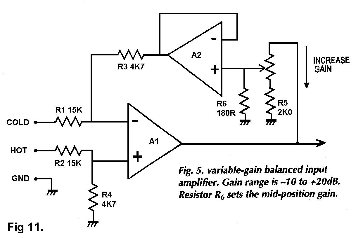
This stage is very useful as a general line input with an
input sensitivity range of -20 to +10 dBu. For a nominal
output of 0 dBu, the gain of Fig 11 is +20 to -10 dB, with R6
chosen for 0 dB at the central wiper position.
An opamp in a feedback path appears a dubious proposition
for stability, but here, working as a voltage-follower, its
bandwidth is maximised and in practice the circuit is
dependably stable.
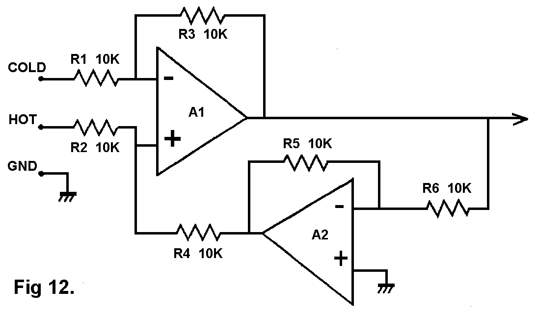
4: The "Superbal" configuration [6] gives much better input
symmetry than the standard differential amplifier. The
differential input impedance is exactly 10k via both hot and
cold inputs. Common mode input impedance is 20k for both
inputs. This configuration is less easy to modify for variable
gain.
5: High-impedance (above 10K) balanced inputs are useful for
interfacing to valve equipment. Adding output cathode-
followers to valve circuitry is expensive, and so the output
is often taken directly from a gain-stage anode. Even a light
loading of 10K may seriously compromise distortion and
available output swing.
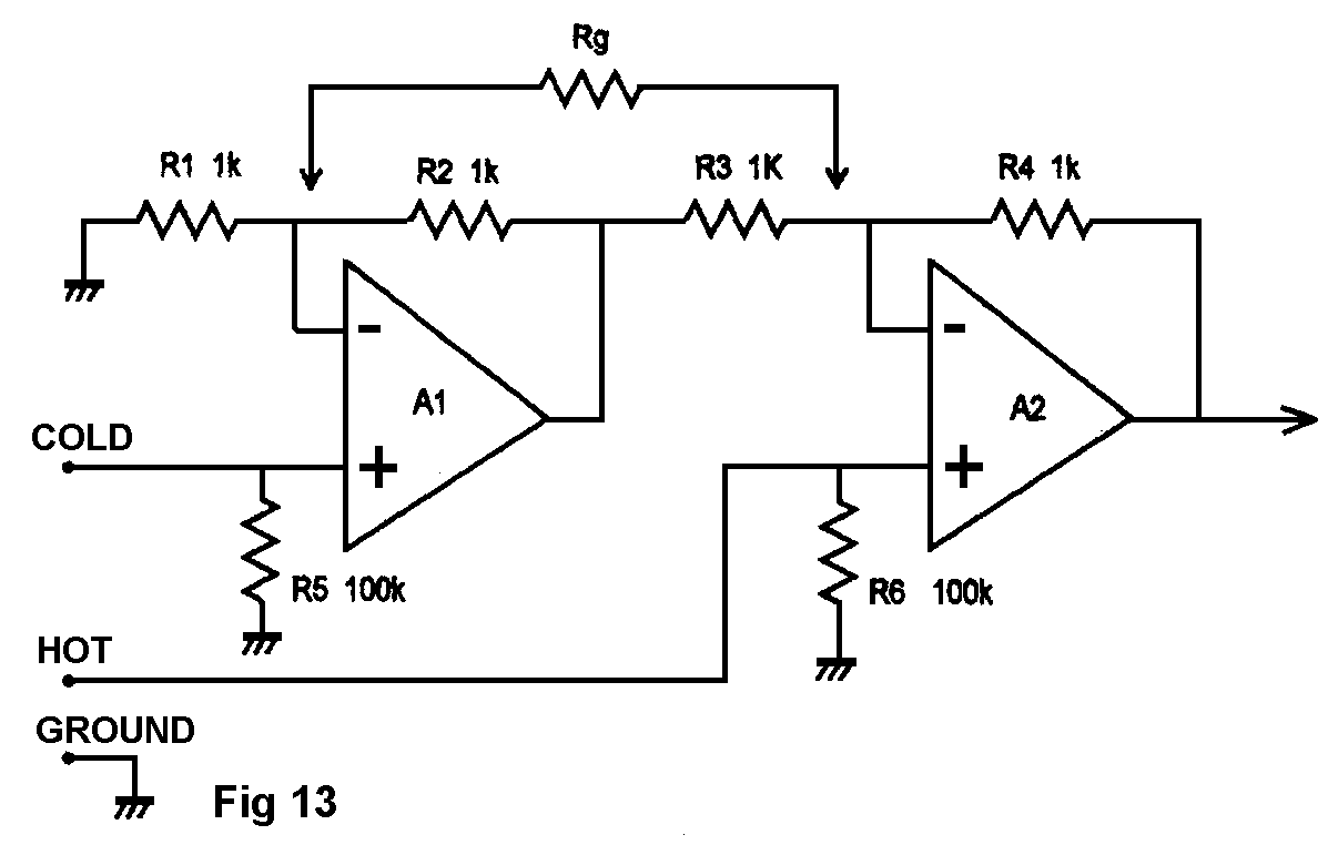
All of the balanced stages dealt with up to now have their
input impedances determined by the values of input resistors
etc, and these cannot be raised without degrading noise
performance. Fig 13 shows one answer to this. The op-amp
inputs have infinite impedance in audio terms, subject to the
need for R,R to bias the non-inverting inputs. [7] Adding Rg
increases gain, but preserves balance. This configuration
cannot be set to attenuate.
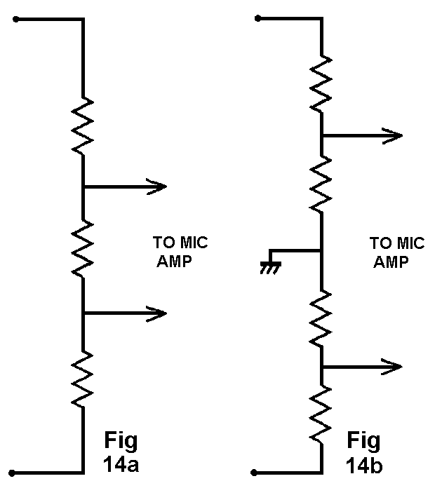
6: It is often convenient to use a balanced microphone preamp
as a line input by using a suitable balanced attenuator,
typically 20 to 30 dB. The input impedance of the mic input
stage will be 1 to 2K for appropriate mic loading, and this
constrains the resistor values possible. Keeping the overall
input impedance to at least 10K means that the divider
impedance must be fairly high, with a lot of Johnson noise, so
the total noise performance balanced is almost always inferior
to a dedicated line input amplifier. CMRR is determined by the
attenuator tolerances and will probably be much inferior to
the basic mic amp, which usually relies on inherent
differential action rather than component matching. Fig 14a
shows a bad way to do it; the differential signal is
attenuated, but not the common-mode, so CMRR is degraded even
if the resistors are accurate. Fig 14b attenuates differential
and common-mode signals by the same amount, so CMRR is
preserved, or at any rate no worse than resistor tolerances
make it.
7: All the balanced inputs above depend on resistor matching
to set the CMRR. In practice this means better than 45 dB is
not obtainable without trimming. If CMRR higher than this is
essential, an IC instrumentation amplifier is one possibility;
CMRR can be in the range 80 to 110 dB, without trimming or
costly precision components. The IC tends to be expensive, due
to low production volumes. Gain is often limited in
range and cannot usually be less than unity.
CMRR of this order is rarely if ever required in audio
work. If the interference is that serious, then it will be
better to eliminate the source of the noise rather than its effects.
6: INPUT/OUTPUT COMBINATIONS
Taking five kinds of output (the rare case of floating
output transformers being excluded) and the two kinds of input
amplifier, there are 10 possible combinations of connection.
The discussion below assumes output Rs is 100 Ohms, and the
differential input amplifier resistors R are all 10k, as in
Fig 9.
Case 1) Unbalanced output TO unbalanced input.
The basic connection. There is no rejection of ground noise
(CMRR=unity) or electrostatic crosstalk; in the latter case
the 1mA notional crosstalk signal yields a -20 dBv signal as
the impedance to ground is very nearly 100 Ohms.
Case 2) Unbalanced output TO balanced input.
Assuming the output ground is connected to the cold line
input, then in theory there is complete cancellation of ground
voltages- unless the output has a series output resistor to
buffer it from cable capacitance, (which is almost always the
case) for this will unbalance the line. If the output
resistance is 100 Ohms, and the cold line is simply grounded
as in Fig 4a, then Rs degrades the CMRR to -46 dB even if the
balanced input has exactly matched resistors.
The impedances on each line will be different, but not due
to the asymmetrical input impedances of a simple differential
amplifier; the hot line impedance is dominated by the output
resistance Rs on the hot terminal (100 Ohms) and the cold line
impedance is zero as it is grounded at the output end. The
rejection of capacitive crosstalk therefore depends on the
unbalanced output impedance, and will be no better than for an
unbalanced input, as at 1); the main benefit of this
connection is ground noise rejection, which solves the most
common system problem.
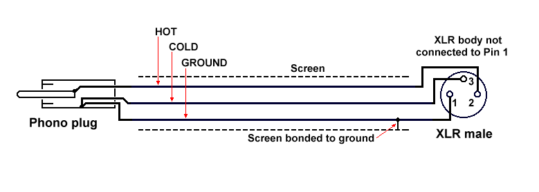
Fig 15 above shows a typical unbalanced to balanced cable. The important point is that the Cold line is connected to ground at the remote (phono) end, and not at the XLR. Thus the balanced inputs at Pins 2 and 3 see only the voltage at the phono plug itself, and any spurious voltages that may exist on the ground line are ignored.
The XLR body, if metal, will have a separate solder tag for making connections to it. It also makes an electrical connection to its mating connector; if this is chassis-mounting then it will usually be grounded so the XLR body tag need not be used. In fact, it is important not to join the body to either ground or Cold as this creates an unwanted connection between audio ground and chassis ground, which may affect system performance.
Case 3) Impedance-balance output TO unbalanced input.
There is nothing to connect the output cold terminal to at
the input end, and so this is the same as the ordinary
unbalanced connection at 1) above.
Case 4) Impedance-balance output TO balanced input.
In theory there is complete cancellation of both capacitive
crosstalk and CM ground voltages, as the line impedances are
now exactly equal.
The table below shows the improvement that impedance-
balancing offers over a conventional unbalanced output, when
driving a balanced input with exactly matched resistors.
Capacitive 1mA CMRR
Conventional -20 dBv -46 dB
Impedance-bal 99R -60 dBv -101dB
Impedance-bal 100R Infinite -85 dB
Impedance-bal 101R -60 dBv -79 dB
The effect of tolerances in the impedance-balance resistor
are also shown; the rejection of capacitive crosstalk degrades
as soon as the value moves away from the theoretical 100 Ohms,
but the CMRR actually has its point of perfect cancellation
slightly displaced to about 98.5 Ohms, due to second-order
effects. This is of no consequence in practice.
Case 5) Ground-cancelling output TO unbalanced input.
There is complete cancellation of ground voltages, assuming
the ground-cancel output has an accurate unity gain between
its cold and hot terminals. (Which is a matter for the
manufacturer) This is a very efficient and cost-effective
method of interconnection for all levels of equipment, but
tends to be more common at the budget end of the market.
Case 6) Ground-cancelling output TO balanced input.
This combination needs a little thought. At first there
appears to be a danger that the ground-noise voltage might be
subtracted twice, which will of course be equivalent to
putting it back in in anti-phase, gaining us nothing. In fact
this is not the case, though the cancellation accuracy is
compromised compared with the impedance-balanced case; the CM
rejection will not exceed 46 dB,even with perfect resistor
matching throughout. Capacitive crosstalk is no better than
for the "Unbalanced output TO balanced input" ie approx -21
dB, which means virtually no rejection; however this is rarely
a problem in practice.
Case 7) Balanced output TO unbalanced input.
This is not a balanced interconnection. There is nowhere to
connect the balanced cold output to; it must be left open-
circuit, its signal unused, so there is a 6dB loss of headroom
in the link. The unbalanced input means the connection is
unbalanced, and so there is no noise rejection.
Case 8) Balanced output TO balanced input.
A standard balanced system, that should give good rejection
of ground noise and electrostatic crosstalk.
Case 9) Quasi-floating output TO unbalanced input.
Since the input is unbalanced, it is necessary to ground
the cold side of the quasi-floating output. If this is done at
the remote (input) end then the ground voltage drop is
transferred to the hot output by the quasi-floating action,
and the ground noise is cancelled in much the same way as a
ground-canceling output.
However, in some cases this ground connection must be
local, ie at the output end of the cable, if doing it at the
remote (input) end causes HF instability in the quasi-floating
output stage. This may happen with very long cables. Such
local grounding rules out rejection of ground noise because
there is no sensing of the ground voltage drop.
Perhaps the major disadvantage of quasi-floating outputs is
the confusion they can cause. Even experienced engineers are
liable to mistake them for balanced outputs, and so leave the
cold terminal unconnected. This is not a good idea. Even if
there are no problems with pickup of external interference on
the unterminated cold output, this will cause a serious
increase in internal noise. I believe it should be standard
practice for such outputs to clearly marked as what they are.
Case 10) Quasi-floating output TO balanced input.
A standard balanced system, that should give good rejection
of ground noise and electrostatic crosstalk.
The hot and cold output impedances are equal, and dominate
the line impedance, so even if the line input impedances are
unbalanced, there should also be good rejection of
electrostatic crosstalk.
7: GROUNDING PHILOSOPHIES.
It has been assumed above that the ground wire is connected
at both ends. This can cause various difficulties due to
ground currents flowing through it.
For this reason some sound installations have relied on
breaking the ground continuity at one end of each cable. This
is called the One-End-Only (OEO) rule. [8] It prevents ground
currents flowing but usually leaves the system much more
susceptible to RF demodulation, as the cable screen is
floating at one end, and is now effectively a long antenna for
ambient RF. There is also the difficulty that non-standard
cables are required, and a consistent rule as to which end of
the cable has no ground connection must be enforced. The OEO
approach may be workable for a fixed installation that is
rarely modified, but for touring sound reinforcement
applications it is unworkable.
A compromise that has been found acceptable in some fixed
installations is the use of 10nF capacitors to ground the open
screen end at RF only; however, the other problems remain.
The formal OEO approach must not be confused with "lifting
the ground" to cure a ground loop. Unbalanced equipment
sometimes provides a ground-lift switch that separates audio
signal ground from chassis safety ground; while this can
sometimes be effective, it is not as satisfactory as balanced
connections. Lifting the ground must NEVER be done by removing
the chassis safety earth; this removes all protection against
a live conductor contacting the case and so creates a serious
hazard. It is also in many cases illegal.
The best approach therefore appears to be grounding at both
ends of the cable, and relying on the CMRR of the balanced
connection to render ground currents innocuous. Ground
currents of 100 mA appear to be fairly common; ground currents
measured in amps have however been encountered in systems with
serious errors. A typical example is connecting incoming mains
"Earth"- which is actually Neutral in many cases- to a
technical ground such as a buried copper rod. (See the section
"Electrical Noise" in Part 1 of this article for more details)
Ground currents cause the worst problems when they flow not
only through cable shields but also the internal signal wiring
of equipment. For this reason the preferred practice is to
terminate incoming ground wires to the chassis earth of the
equipment. This keeps ground currents off PCBs, where the
relatively high track resistances would cause bad common-
impedance coupling, and preserves RF screening integrity.
Grounding is simplified for source equipment that has no
other connections, such as double-insulated CD players and so
on. These carry a "square-in-a-square" symbol to denote higher
standards of mains insulation, so that external metalwork need
not be grounded for safety. Such equipment often has
unbalanced outputs, and can usually be connected directly to
an unbalanced input with good results, as there is no path for
any ground currents to circulate in.
If a balanced input is used, then connecting the hot input
to CD signal and the cold to CD "ground" leaves the CD player
ground floating, and this will seriously degrade hum and RF
rejection. The real ground must be linked to CD player common.
Balanced line interconnections are rather more complex than
is immediately obvious. Having said that, with a little
caution they work very well indeed.
| DIAGRAMS.
|
| Fig 1 | Electrostatic coupling into a signal cable. Rs is
100 Ohms and R is 10k. The second Rs to ground in
the cold output line makes it an impedance balanced
output.
|
| Fig 2 | Magnetic coupling into a signal cable, represented
by notional voltage-sources Vm.
|
| Fig 3 | Ground-voltages coupling into a signal cable. The
ground voltage between A and B is due to ground
currents flowing around ABCD
|
| Fig 4a | An unbalanced line output. The cold output (if it
exists at all) is connected directly to ground.
|
| Fig 4b | An impedance balanced output. The cold output is
connected to ground through a second Rs of identical
value.
|
| Fig 5a | A ground-cancelling output, with a unity-gain path
from the cold terminal to the hot output. Once more
a second Rs balances the line impedances.
|
| Fig 5b | A balanced output. A2 is a unity-gain inverter
driving the cold output. Line impedances are
balanced.
|
| Fig 6 | Simplified diagram of a quasi-floating balanced
output, with its essential trim control for output
symmetry.
|
| Fig 7 | A variable-gain series-feedback unbalanced input
stage. R2 sets mid-position gain.
|
| Fig 8 | A shunt-feedback configuration, with a low and
variable input impedance.
|
| Fig 9 | The standard one-opamp differential amplifier,
arranged for unity gain.
|
| Fig 10 | A switched-gain balanced input amplifier. The values
shown give gains of -6 dB and +6.2 dB, for switching
between pro and semi-pro interface levels.
|
| Fig 11 | A variable-gain balanced input amplifier. Gain range
is -10 to +20 dB. R6 sets the mid-position gain.
|
| Fig 12 | The "Superbal" balanced input stage; input impedance
on hot and cold are equal for both differential and
common mode.
|
| Fig 13 | A hi-Z balanced input stage; R5 and R6 set input
impedance, and can be much higher. Add Rg to
increase gain.
|
| Fig 14 | Balanced attenuators to convert a microphone preamp
to line input. 14b is superior as both differential
and CM signals are equally attenuated, so CMRR is
not degraded more than necessary.
|
| REFERENCES.
|
| 1] Williams, T | "EMC for Product Designers."
Newnes (Butterworth-Heinemann) pub 1992
ISBN 0 7506 1264 9 p176
|
| 2] Williams, T | As [1] above, p173.
|
| 3] Muncy, N | "Noise Susceptibility in Analog and
Digital Signal Processing Systems."
JAES Vol3 #6, June 1995, p447
|
| 4] Muncy, N | As [3] above, p441
|
| 5] Winder,S | "What's The Difference?"
Electronics World, Nov 1995, p989.
|
| 6] Ballou G (ed) | "Handbook For Sound Engineers- The Audio
Cyclopaedia" Howard Sams 1987.
ISBN 0-672-21983-2 (Superbal)
|
| 7] Smith J L | "Modern Operational Circuit Design"
Wiley-Interscience, 1971, p31,241.
|
| 8] Muncy, N | "Noise Susceptibility in Analog and
Digital Signal Processing Systems."
JAES Vol3 #6, June 1995, p440
|


