Gallery opened 29 Feb 2020
Updated 8 Mar 2020


Turbine-powered Paddle Boats |
Gallery opened 29 Feb 2020 |
Paddle boats were used as harbour tugs long after their use had been abandoned on larger vessels, because of their great manoeuvrability. By turning the side-paddles in opposite directions a tug could turn round on the spot. Paddle tugs almost always had reciprocating engines, usually one per paddle, as they were easily reversed. Turbines, on the other hand, are not reversible; but the Dordrecht was a river tug rather than harbour tug, and was built to tow trains of barges; very great manoevreability was not required. Presumably the idea was that turbines would be more efficient than reciprocating engine for a river tug. The idea does not seem to have caught on, as the four ships listed below are the only turbine paddle-steamers currently known. Perhaps the introduction of the Diesel engine had something to do with this.
Three experimental paddle tugs powered by turbines were built for use on the River Rhine in the mid 1920s, and one on the River Rhone. At present the Dordrecht is the only one of the four on which information has been found.
Vessel BuilderTurbine supplier
PT Zurich (1922) Escher Wyss (Zurich)PT Dordrecht (1925) Schiffs-und Maschinenbau Gesellschaft (Mannheim) Brown Boveri Company
PT Toulon (1929) Sachsenberg Parsons
PT Rhone (1931) Escher, Wyss (Zurich) |
 | Left: The Dordrecht turbine paddle tug: 1925
|
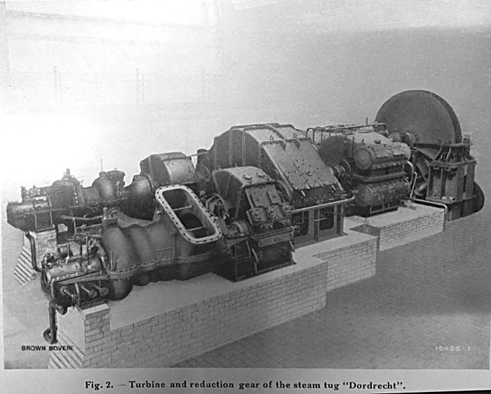 | Left: The turbine installation of the Dordrecht: 1925
|
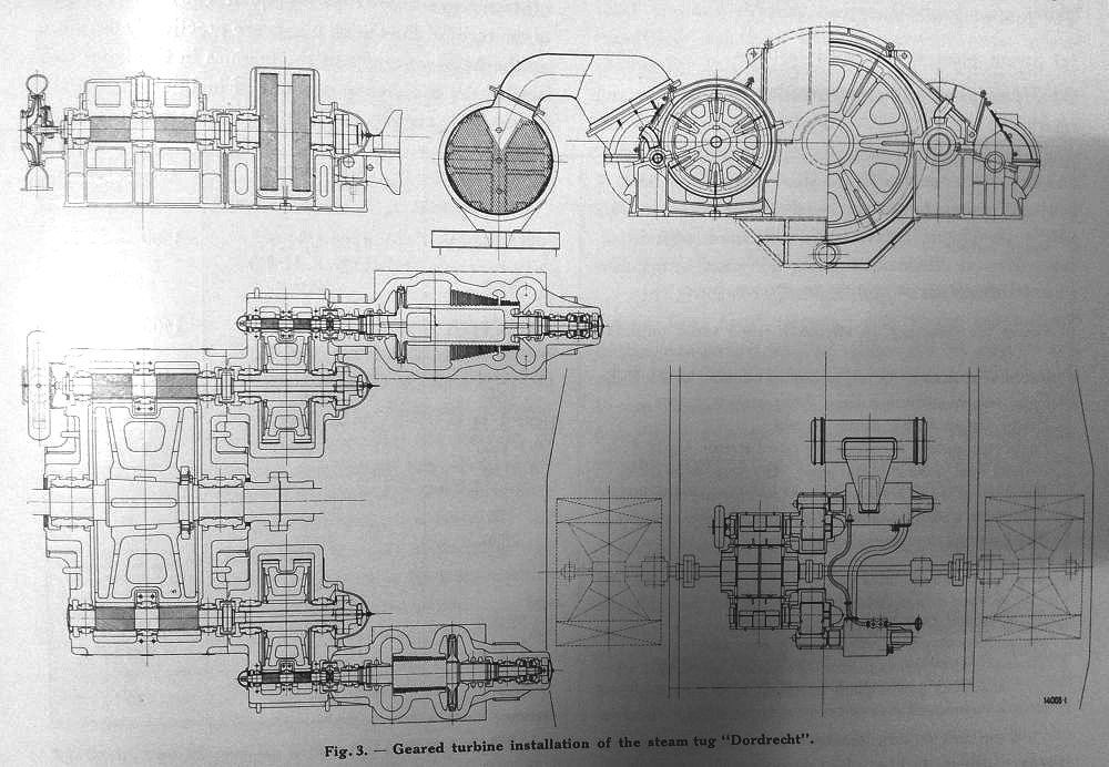 | Left: The turbine installation of the Dordrecht: 1925
|
![]()

|