The steam traction engine was for a long time a vital means of freight transport, and for providing power on the spot for ploughing, threshing, funfairs, and so on. They were the mainstay of agriculture from the end of the mid 1800's to the 1930s ,when they were replaced by the early petrol tractors. Until heavy lorries appeared they were the only way to move items that were too large to go by rail, such as ship boilers. You can good a idea of how conventional traction engines looked on Wikipedia.
However, as in most forms of engineering endeavour, there some unconventional designs of varying merit; some were ingenious, some less than inspired. You can see some of them here.

TRACTION ENGINE BASICS
The power of traction engines was measured in peculiar units called 'Nominal Horse Power'. This was calculated solely from the piston area, ignoring the piston stroke and the steam pressure. It therefore only had a very tenuous connection with any measure of real power, but nevertheless seems to have somehow persisted to the end of the traction engine era. NHP are quoted here but treat them with the greatest of caution.
Traction engines had either a 3-shaft or a 4-shaft transmission system. The 3 shafts were the crankshaft, the counter shaft and the rear axle itself. 4-shaft designs had an extra countershaft; they were generally thought to be less durable.
UNUSUAL DRIVE TRAINS
The majority of traction engines transmitted their power to the rear wheels by spur gearing, via 3 or 4 shafts, as explained above. A problem with this was that it required a fixed rear axle with no suspension movement, in order to keep the final pair of gears in proper mesh.
Various methods were used to address this problem, including coupling rods like those used on railway locomotives.
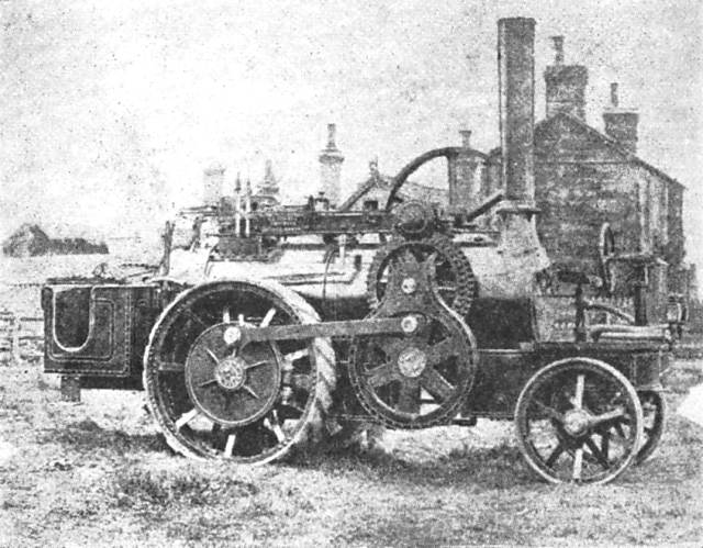 |
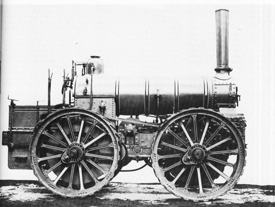
| Left: An engine built by Fowell to Box's patent: 1877
This engine, of 8 nominal horse-power, implemented the final stage of drive through coupling rods, rather like a steam locomotive. This allowed vertical motion of the sprung rear wheels. The lower countershaft ran underneath the boiler to drive the rear wheel on the other side via another crank and coupling rod, presumably set at 90 degrees to avoid dead-centre problems. This arrangement was patented by William Box in 1876. Note the front steering position. The middle counter-shaft has two sets of teeth to allow changing gear.
This engine (numbered Fowell No 2) was delivered to William Box in May 1877 and seems to have been entirely successful. In the first two years of its life it covered 3000 miles hauling loads of 15 to 25 tons, and after 20 years it run over 30,000 miles.
Note also that Fowell is NOT a misprint for Fowler. Fowell was a quite different company manufacturing traction engines. Fowell built a second Box patent engine (No 18) that was delivered in July 1882, and a third (No 30) was delivered in May 1884. A fourth (No 41) was delivered in 1888, and that was Fowell's last of this type.
However, another source (The Big Box) states that Fowell built five of these engines
|
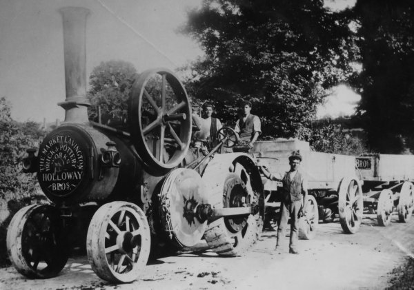 |
| Left: The second Fowell Box-patent engine, No 18: 1882
The engine belonged to The Market Lavington Brick and Pottery Works, owned by Holloway Brothers. Concern over the breakage of bricks due to the rough haulage by a traction engine with no rear suspension was the original impetus to develop the Box patent.
This engine ran over and kllled its original purchaser, William Box senior, in 1894.
The steersman here is one Charlie Sheppard. There is a band-brake on the drive wheel of the lower countershaft.
|
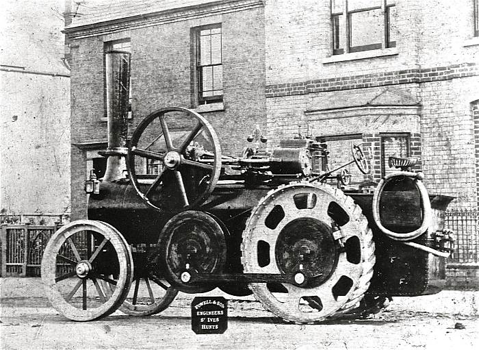 |
| Left: The fourth Fowell Box-patent engine, No 41: 1888
Of 8 nominal horse-power. It looks essentially identical to No 18 above.
No photograph has so far been traced of the third Fowell Box-patent engine, No 30, but it is known it was called "Lion".
|
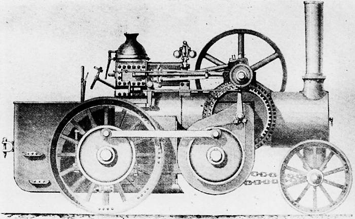 |
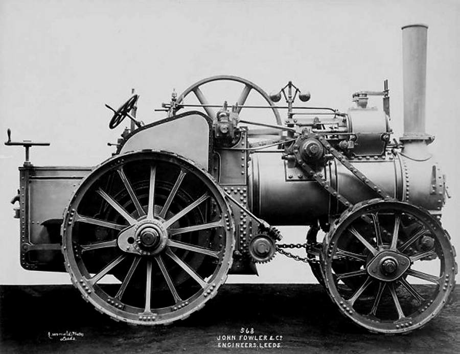
| Left: A drawing of the Box patent engine built by Robey: 1879
The Robey company also built a Box patent engine in 1879.
The design is rather more conventional than the Fowell version. Here the rear axle is behind the firebox instead of in front of it, and there is a conventional steering position at the rear. Once again the middle counter-shaft has two sets of teeth to allow changing gear.
There is a band-brake on the drive wheel of the lower countershaft, controlled by a handwheel visible below the cylinder.
Another source (The Big Box) states that Robey built two of these engines
|
FOUR-WHEEL DRIVE TRACTION ENGINES
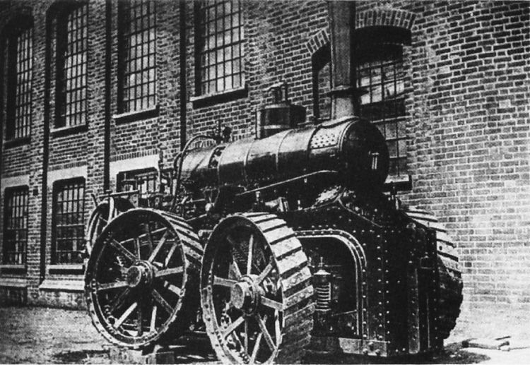
Four-wheel drive for a traction engine seems like a very good idea because the considerable weight resting on the front wheels can be used for adhesion; however the mechanical complexities were such that the idea did not thrive. This undertype (engine below boiler) traction engine was built by Fowler using the patent of John Whittingham. (Patent No 3860 of 1880) The rear wheel appears to be driven by a chain enclosed in a case; it is not wholly clear how the front axle was driven.
 |
|
Above: Four-wheel drive Fowler engine: circa 1880
The engine proved to be "deficient in the compensating gear" which I assume means there was trouble with a differential between the front and rear wheels. According to US Patent 316,774 (see below) "In an arrangement known as “Whittingham’s gear’ the leading wheels of a traction-engine are driven without interfering with the locking of the axle. The axle is surrounded by a pair of rings and parts are connected by gimbal-joints." This seems to mean there was no differential on the front axle, so that while power could be transferred to it whatever the steering angle, the two front wheels could not rotate at different speeds when cornering. It all sounds a bit crude and my theory that there was some sort of differential between the front and rear drive now looks unlikely. |
 |
|
Above: Improved four-wheel drive Fowler engine: 1885
This is an improved version built by Fowlers four years later, exploiting US Patent 316,774 of 1885, issued to R.H. Shaw, A. Greig, & John Whittingham for a better way of driving the front wheels. It was a compound engine and carried Number 4920. It is recorded that it was a rebuild of The Steeplechaser but I can see no points of resemblance.
In this engine the front axle had a bevel-gear differential in the middle, which was driven by a horizontal shaft just ahead of the steering pivot. The chain drive to this shaft from the engine is clearly visible. The design had no commercial success.
|
 |
| Left: Four-wheel drive Tasker engine: 1893
This is a Tasker engine fitted with the Diplock four-wheel system, here demonstrating that it had independent suspension on all four wheels. It was built for
This looks like an undertype (engine below boiler) engine. William Tasker & Sons were based at Waterloo Foundry, Abbotts Ann, Hampshire, Hampshire, where they made conventional traction engines and steam-rollers.
|
 |
| Left: Four-wheel drive Tasker engine: 1893
This appears to be the only other picture of the engine in existence. The engine was built for Bramah Joseph Diplock, who invented the four-wheel drive system that was used; he patented it in 1893. (Patent No. 19,682) He went to invent the Pedrail. (below)
This is clearly a undertype (engine below boiler) engine.
|
FRONT STEERING ENGINES
Front-steering looks a bizarre notion to modern eyes, but it was not that uncommon in the early years of traction engines. It simplified the steering gear, and had the advantage that the steersman in front had an excellent view of the road ahead, and indeed of any impending accident. With several tons of traction engine behind him, his only hope would be to jump for it, and it is perhaps significant that most of these early steering platforms had no guard-rails so the steersman could abandon ship in a hurry.
One wonders about communication between steersman and the driver at the rear; having a noisy steam-engine between them cannot have helped.
Almost all pictures of front-steering engines show a young lad doing the steering while the driver is an older and more authoritative bearded figure. We may conclude that the driver was in charge. Since he had to manipulate the throttle, fire the boiler, keep the water-level safe, and more, a responsible fellow was required.
 |
| Left: Front-steering Tuxford-Boydell engine: 1858
As to the unusual features on this Tuxford engine, front-steering is just the start. The engine is a three-wheeler, and the wheels are Boydell wheels.
A vertical boiler was located at the rear, with a coal bunker and driver's footplate behind it.
|
 |
|
Above: Front-steering Savage engine: 18??
This front-steering Savage engine was built for Samuel Wright of Rutland. It is displayed here in King's Lynn, with Fredetrick Savage himself on the footplate.
|
UNUSUAL WHEEL ARRANGEMENTS
 |
| Left: Monorail traction engine
This engine may be related to the Anglovaal mining monorail system, but this is still under investigation. It may have been built by Wallis & Steevens of Basingstoke.
There appears to be a bearing between the two small front wheels, to allow the front assembly to tilt on uneven track.
This sort of machinery blurs the distinction between traction engines and railway locomotives. Looking at some other examples, I would classify the Patiala monorail engine as a locomotive because the rail wheels carry almost all the weight and do the driving. The same is true for the Roadrail system.
On the other hand, the Larmanjat system used the rails for guidance but propelled itself by its road-wheels, so was arguably more of a traction engine, like the machine shown here.
|
Virtually all traction engines had four wheels, but some had three. This usually turned out to be a bad idea.
 |
| Left: A 3-wheeled Fowler traction engine
It is not known why Fowler, a respected British builder, started producing 3-wheeled traction engines in 1871. Four engines were shown at the Royal Agricultural Show, Wolverhampton, in that year; two of 6 and two of 12 NHP. A steam dome was placed on top of the steam-jacketed cylinder. All were 3-shaft engines. They had enveloping side skirts, not for safety, but so that the sight of moving gears would not frighten horses. For the same reason the flywheel spokes were covered with a plate to make the rotation less obvious.
|
The 3-wheelers were claimed to turn more easily and run more quietly. However, they ran into trouble on country roads as the central front wheel tended to run sideways off the central raised bit of road between the wheel ruts. They were also inclined to rear up when pulling heavy loads, as there was less weight at the front than on a conventional four-wheeled engine.
UNUSUAL WHEELS
 |
|
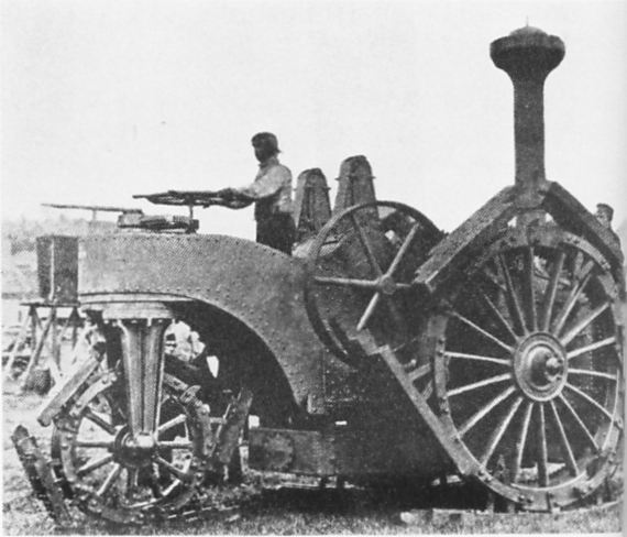
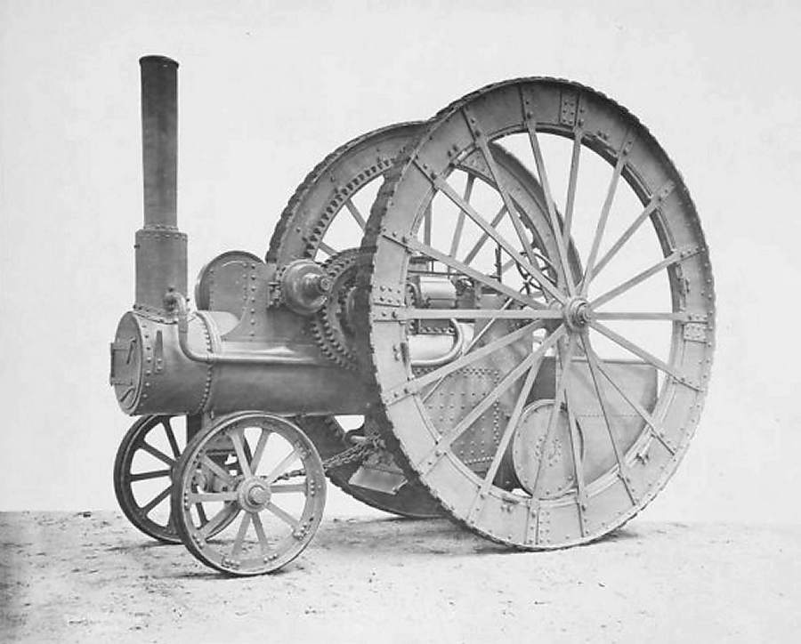
Above: The Steeplechaser with 12-foot rear wheels. The pipe running forward goes to the blastpipe in the base of the chimney: 1877
This extraordinary machine was built by Fowler in 1877. The 12-foot (3.66m) wheels were intended to reduce the ground pressure and give better propulsion in soft soil. Twin cylinders were mounted over the firebox; the forward crankshaft drove a countershaft running across the boiler through a 2-speed gear and differential. Pinions at each end of this countershaft engaged with a circular rack bolted inside the rim of each rear wheel; this can be clearly seen in the photograph. The rear weight was not carried on the rear axle, but, via leaf springs, on a lower shaft with a double flanged wheel at each end. These ran on a circular track on the insde of the wheel rims.
Not surprisingly, this machine proved too clumsy to be useful, but that did not stop Fowlers from producing a similar machine two years later with 9-foot (2.7m) driving wheels. The usual maximum diameter was 7-foot.
|
 |
|
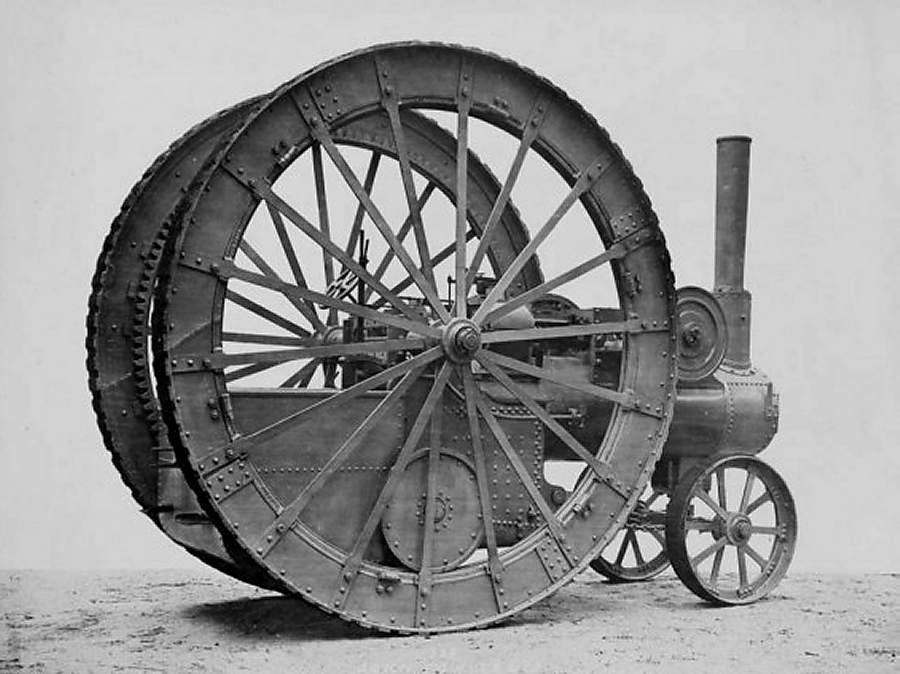
Above: The other side of Steeplechaser: 1877
|
 |
|
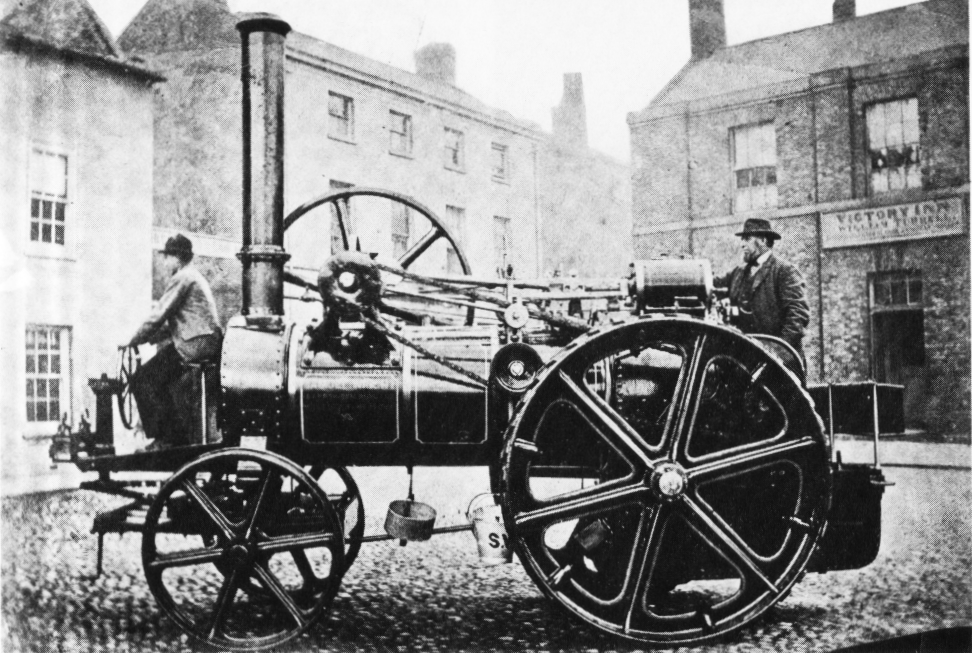
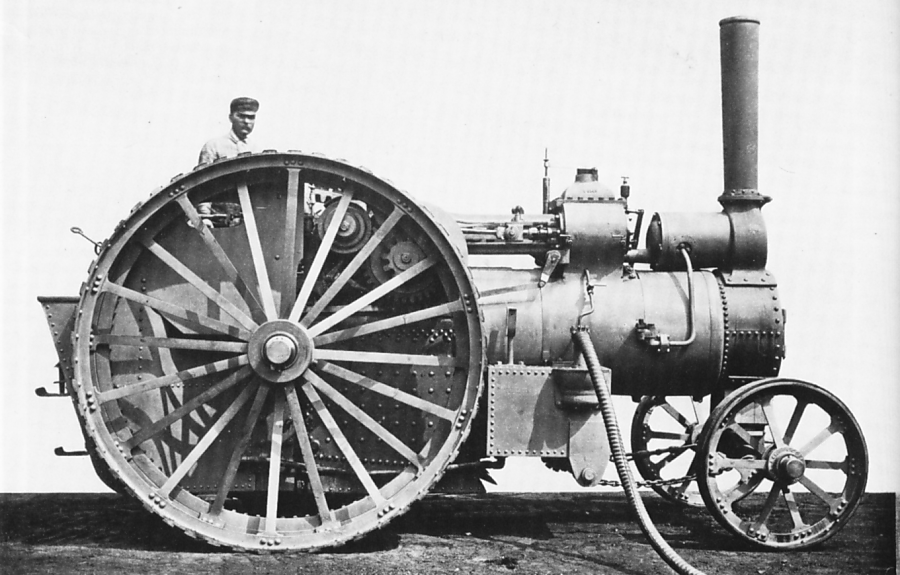
Above: The Fowler 'nine-footer' No 3811: 1879
Not so extreme, but still with very large 9-foot wheels, was the double-cylinder 8nhp Fowler built in 1879 for Lord Amherst of Didlington, Norfolk, UK. Drive was to an annular gear-ring on the inside of the rear wheel. The cylinder to the left of the chimney is the feedwater heater; note the pipe going down to the clack valve on the side of the boiler.
This looks quite a practical piece of machinery but no more were sold.
|
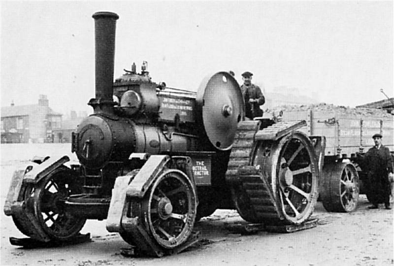 |
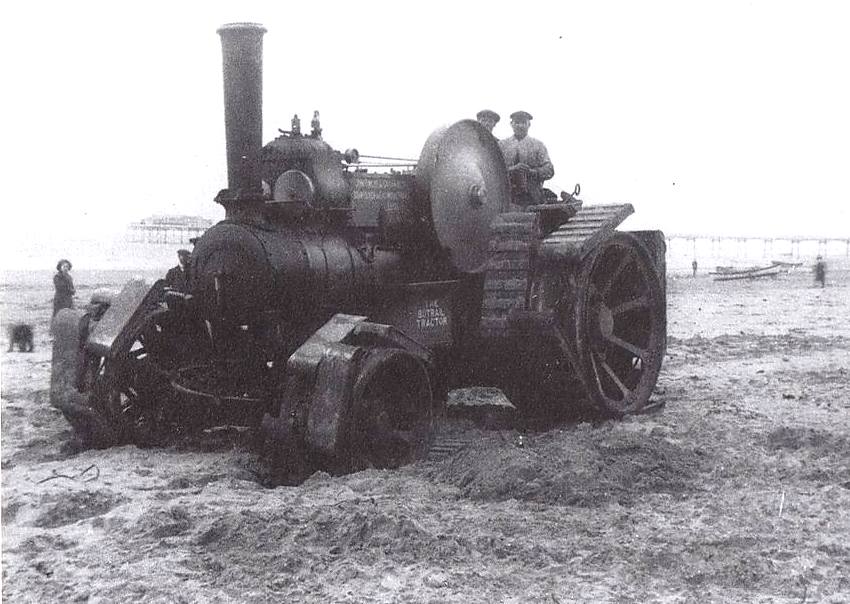
| Left: Fowler compound engine fitted with experimental Botrail tracks
This engine started life in 1912 as a standard Fowler Class R3 road locomotive, but early the following year was fitted with the Botrail arrangement of steel shoes held on by steel cables.
The photograph shows trials on Redcar Sands on 22nd April 1913. Two heavily laden trucks were towed.
|
The Botrail was invented by Frank Bottrill, engineer, of 41 Moubray Street, Albert Park, State of Victoria, Australia. He was issued with British Patent 8844 (in 1912) for "Improvements relating to Ped-rail Shoes for Heavy Road Vehicles".
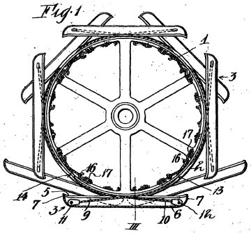 |
| Left: The Botrail wheel, taken from patent 8844.
Each of the 8 shoes has two steel cables attached at each end.
|
 |
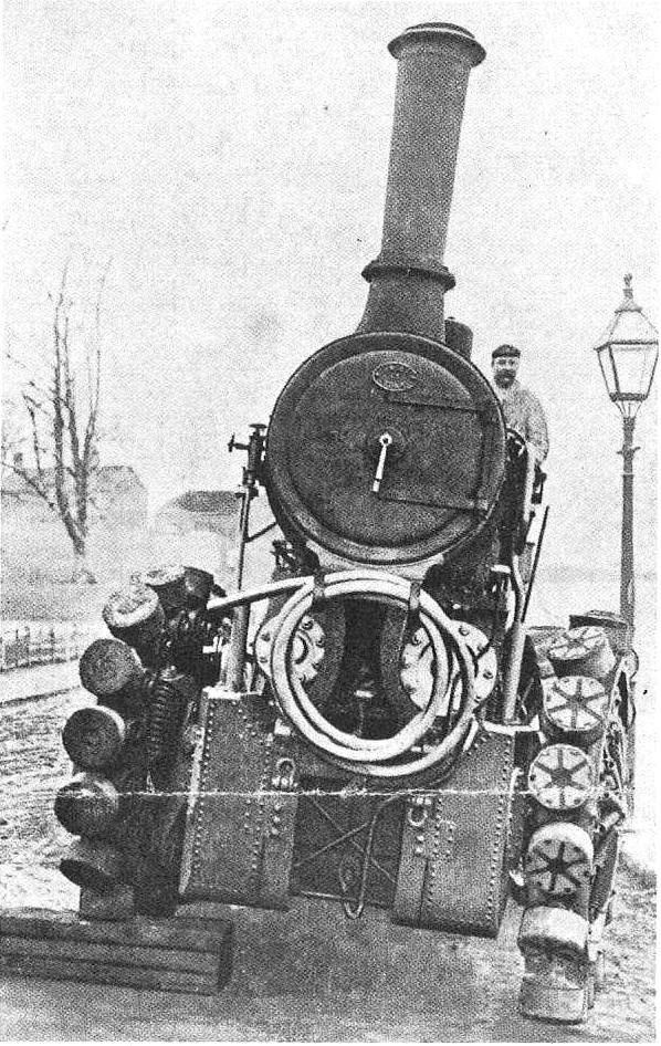
| Left: Another photograph of the experimental Botrail engine at Redcar Sands
|
 |
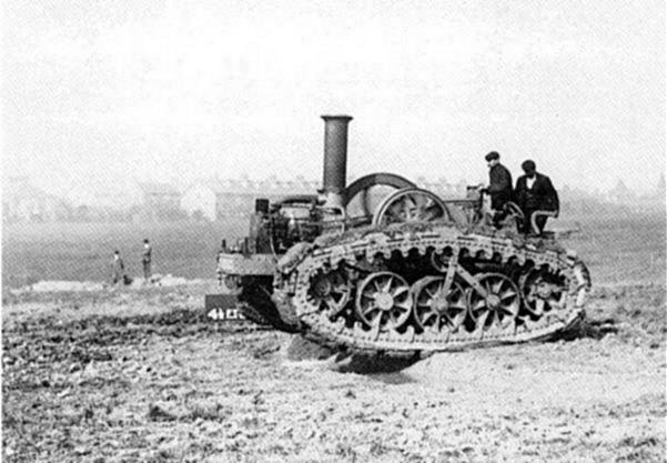
| Left: A demonstration of the Pedrail wheels
The pedrail wheel was invented in 1903 by Bramah Joseph Diplock, of London. Like the Botrail it was intended to allow traction engines to move over difficult terrain. It consisted of circular rubber-shod "feet" attached to the wheel by ball-and-socket joints and sliding spokes. A system of springs and levers inside the wheel kept the appropriate feet in contact with the ground. There is more info on Wikipedia.
The Pedrail concept was abandoned when it became clear that caterpillar tracks were a more durable way of moving over rough ground.
|
TRACTION ENGINES WITH CATERPILLAR TRACKS
Caterpillar tracks were sometimes fitted to traction engines, and proved more effective than the foot-wheel arrangements shown in the previous section. These were the seeds and weak beginnings of the WW1 tank. The history in this section has now been sorted out.
 |
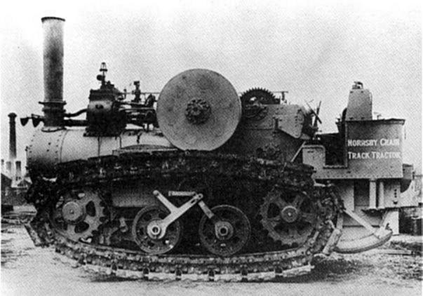
| Left: Hornsby tracked vehicle driven by paraffin engine: 1905
A chain-track was added to a paraffin-engined tractor by the chief engineer of Hornsby, David Roberts, and was patented in July 1904. In 1905 Roberts demonstrated this tractor unofficially to the British Army's Mechanical Transport Committee. A formal demonstration was staged at Grantham in February 1906. The idea was to use it for gun haulage, rather than as a prototype tank, but the Royal Artillery was unenthusiastic.
Three oil-powered engines for gun haulage were made, plus the steam crawler displayed below. One oil crawler survives in working condition at the Bovington Tank Museum.
Note the very steam-type chimney, to carry the exhaust away from the crew. No doubt this was a spare part from a steam traction engine. The Wikipedia entry on the Richard Hornsby company identifies it as a steam tractor, which seems to be incorrect. There is no sign of a boiler. The vehicle is clearly moving, as shown by the blurred spokes of the flywheel, but there is not a trace of steam visible anywhere.
|
While this machine is often credited with being influential in the development of the tank, serious study of the possibilities of tracked tanks did not begin in Britain until 1914.
Counter-intuitively, the Hornsby steam tractor was built after the paraffin-powered versions, in 1910.
 |
| Left: The Hornsby steam crawler: 1910
This machine was shipped to Canada from England in 1910, being sold to the Northern Light Power & Coal Company for use hauling coal to the Klondike gold fields in the Yukon, where it worked until 1927. This was the only sale, and the Hornsby company became disillusioned with their "chain track"and sold the patent rights to the Holt Manufacturing Company in 1914.
|
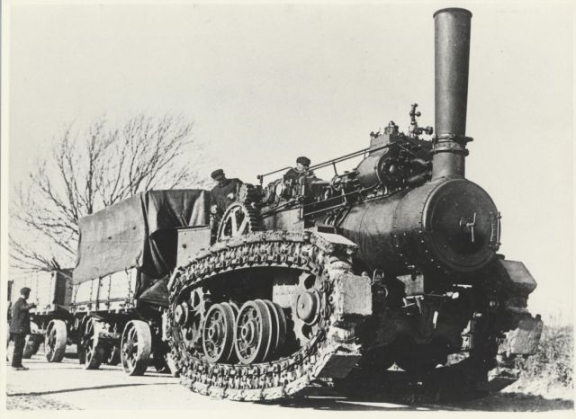 |
| Left: The Hornsby steam crawler: 1910
Sadly only the tracks of the steam crawler survive. They can be seen on this very fine website dedicated to the Hornsby steam crawler.
|
 |
|
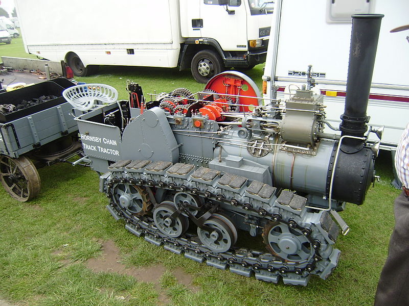
Above: A model of the Hornsby tracked traction engine
This fantastic piece of work is is a model of the Hornsby engine built to 4-inch scale. I assume this means 4 inches to the foot, ie one-third scale. Pictured here at the Lincoln (England) steam fair in 2008. You can see this wonderful thing in action on YouTube. It is owned by Steve Baldock.
|
UNUSUAL STEAM ARRANGEMENTS
The traction engine shown below is very unusual in that it has a condenser to recover the the exhaust steam for re-use in the boiler. In fact it may be unique as Googling "condenser traction engine" returns absolutely nothing.
 |
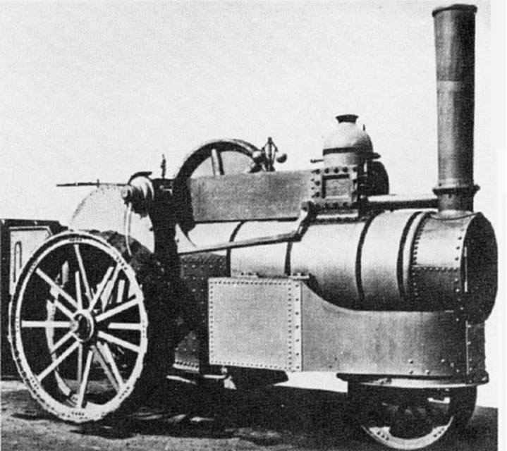
| Left: Wallis & Steevens condensing traction engine
This engine was built by Wallis & Steevens of Basingstoke. The condenser is the tubular affair sat on top of the usual canopy. The rather crude-looking right-angled pipe to the right of the chimney presumably takes the exhaust up to the condenser, though it seems a bit small for the job.
The condenser was designed (presumably under licence) according to British patent 14872 (date 1887) taken out by Frederick John
Burrell, a member of the family who owned Charles Burrell & Sons, of St Nicholas Works, in Thetford, Norfolk. It was intended to be "An improved condenser for tramway locomotives". See R H Clark Chronicles of a country works and Steam engine builders of Norfolk.
|
The engine was works number 2362. It has a single cylinder 9 3/4" x 12" and used a relatively low steam pressure of 120psi. The rear wheels were 6' 6" in diameter, and 20" wide.
This idea utterly failed to catch on, probably because it was easier to arrange for conventional watering rather than carry around the weight of a condenser. Since the extra weight was at the top it would have made the engine more subject to turning over; this was not uncommon with conventional traction engines, and top weight would have made it worse.
Condensing steam trams were relatively common.
ARMOURED TRACTION ENGINES
In 1900 armoured traction engines were used by the British in the Boer War, as shown below.
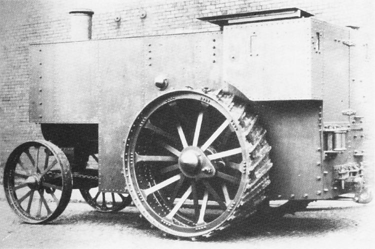 |
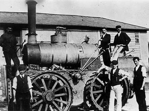
| Left: Armoured Fowler traction engine: 1900
This engine, Fowler No 8894, was fitted with 4.5 tons of armour plate; it already weighed 17.5 tons beforehand. Mirrors were fitted to give the driver a view down the left side of the boiler.
|
UNDERTYPE TRACTION ENGINES
Some traction engines had the steam cylinders, crank, and flywheel under the boiler instead of on top. This may have made access easier but it also made the centre of gravity a good deal higher. At present the Avery is the only undertype traction engine known. Undertype steam wagons, on the other hand, were common.
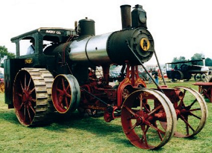 |
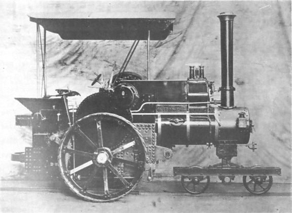
| Left: Avery undertype traction engine: date unknown
This is an Avery 20 HP engine. According to their advertising material, their machine was more durable because the engine was mounted on its own steel frame, and not on top of the boiler, which latter would therefore be more free of stress and strain.
|
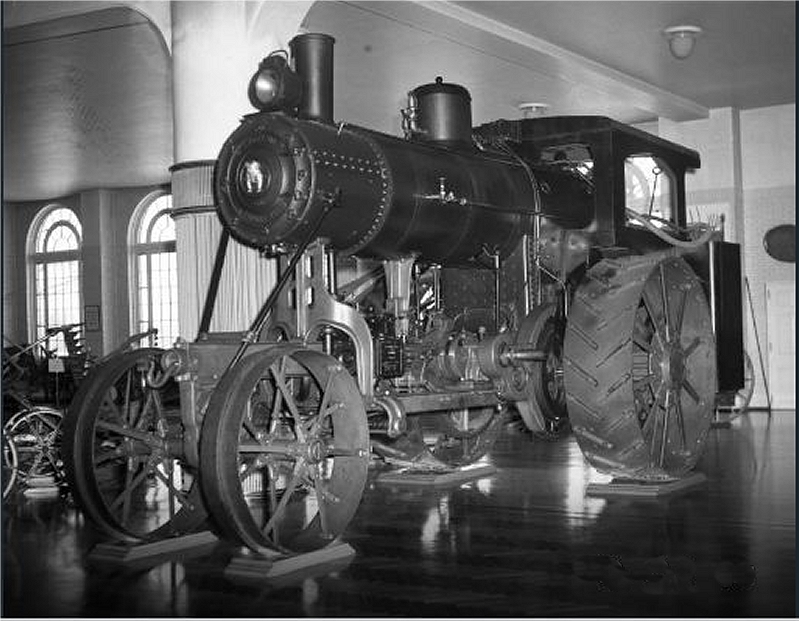 |
| Left: Avery undertype traction engine: 1916
This is an Avery 30 HP engine, weighing 23 tons. It is in the Henry Ford Museum.
There is a short but very fine video of an Avery in steam here.
|
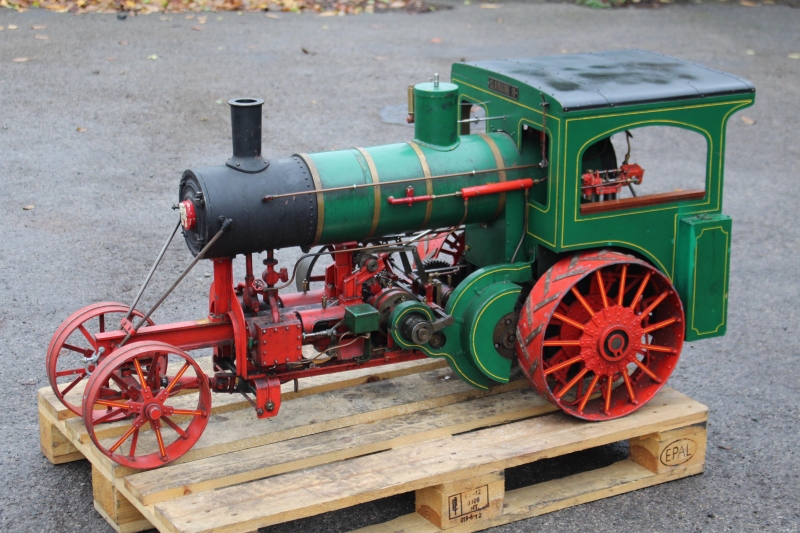 |
| Left: Avery undertype traction engine: 1916
This is a 2.5 inch scale model of an Avery engine, which gives a better view of the machinery. There are two road speeds,engaged by separate dog clutches, one each end of the second shaft, and driving the rear wheels through a differential.
There is a short but very fine video of an Avery in steam here.
|
UNKNOWN McLAREN TRACTION ENGINE
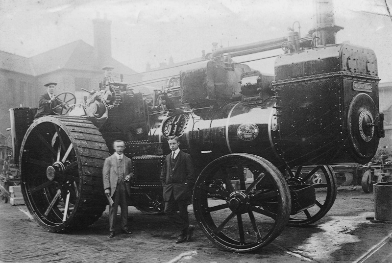 |
| Left: McLaren traction engine: date unknown
Found on the Net.
This enigmatic machine is a 125HP P2-class McLaren traction engine; on the original image the name McLaren can be read on the oval badge at the front of the boiler. On the front of the very odd smoke box, a rectangular nameplate reads: "NEC PLUS ULTRA", which is Latin for “nothing further beyond”; if this was a boastful McLaren motto the Museum Staff have been unable to confirm it.
This is a very strange design; one possibility that occurred to me was that this was a compound engine, and McLaren were attempting to increase efficiency by reheating in the smokebox the steam passing from the HP to the LP cylinder; as you will see, this ingenious idea was actually quite wrong...
Back in August 2022 I received some very useful info from Jonathan Palterman. Jonathan, if you're still watching I apologise for the delay. Here goes:
On the top of the boiler is the well-lagged cylinder; to the left the small rectangular box is the feed-water heater. The upwardly extended smokebox contains the superheater, for which Mclaren obtained patent 27,260 of 1910. This is believed to be Works No 1406, a 125HP P2-class engine; it was capable of producing 140HP for short periods.
|
While it's not legible in this image, the circular nameplate on the smokebox door carries the names Caccialanza & Bronzini, who were agents at Piacenza importing McLaren traction engines into Italy around 1910. See here on Flickriver.


