There is now a page on steam aeroplanes in Wikipedia.
The very first successful aeroplanes were powered by internal-combustion engines. They were naturally inefficient and heavy by today's standards, but there was still no doubt at the time that they were a far more practical power-plant for aviation than the most sophisticated steam engine available.
However, there were a few later attempts to demonstrate that steam had something to offer the aeroplane. 1933 in particular seems to have been a propitious time.
Now read on...

STEAM AEROPLANE ATTEMPTS BEFORE THE WRIGHT BROTHERS
There were many earlier attempts to build steam powered aeroplanes; here are a few notes on some of them. Bear in mind that the Wright brothers were the first to really solve the problem of making an aeroplane controllable in three dimensions, and if any of the early attempts at manned flight outlined below had actually taken off, their pilots would probably have lived to regret it. Though not for long.
JOHN STRINGFELLOW: 1848
John Stringfellow (1799 - 1883) of Sheffield, England was an important pioneer of flight, working with William Henson. He achieved the first powered flight of a model aircraft in a disused lace factory in Chard in 1848. The model had a 10 foot (3m) wingspan, and was powered by a steam engine. The ultimate goal was an Aerial Steam Carriage capable of carrying passengers up to 1000 miles.
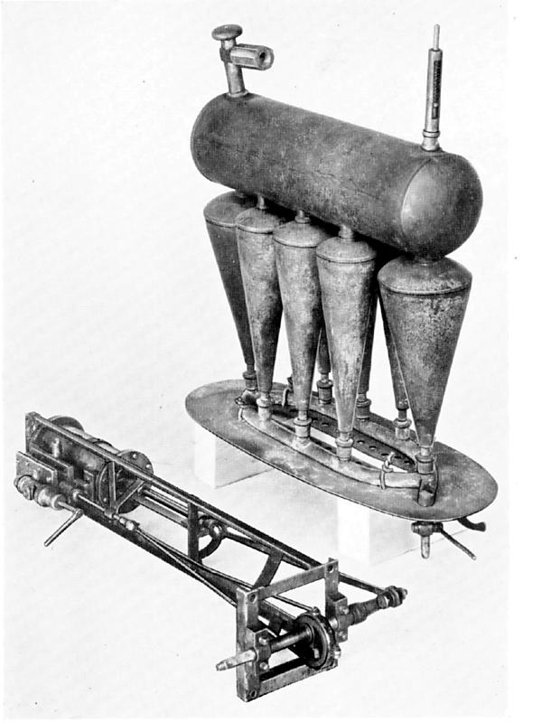 |
| Left: The engine and boiler of Stringfellow's 1848 model
The engine cylinder has a bore of 3/4-inch and a stroke of 2 inches. A bevel gear on the crankshaft gave the propellors three times the rotational speed of the engine.
The boiler consisted of a set of cones acting as water-tubes, connected to a cylindrical steam reservoir above.
The weight of the whole model, including water and fuel, was less than 9 pounds.
From Henson and Stringfellow: Their Work in Aeronautics" by M Davy, Science Museum 1931
|
THE MOSHIASKY STEAM PLANE ATTEMPT: 1884
Alexandr Fyodorovich Mozhaisky, was a Russian naval officer, aviation pioneer, researcher and inventor. He was born in 1825 in Finland. He built a steam-powered plane in 1882, but it is generally agreed it did not achieve sustained flight; for one thing the wings did not have an aerofoil section. At one time Russia claimed that Mozhaisky had anticipated the Wright brothers by achieving sustained and controlled flight, but nobody believed it then and nobody believes it now.
A correspondent sent me this: "The Moshaisky steam plane engine is in the aviation museum in Monino near Moscow and as far as I remember one or two other aviation steam engines."
Originally it was powered by two steam engines with a total power of 30 HP. New steam engines with a total of 50 HP were planned but were not completed before Mozhaisky's death in 1890, and the project was abandoned.
The Mozhaisky plane has a Wikipedia page but there is little info on the steam engines.
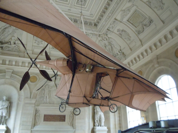
CLEMENT ADER: 1890
Frenchman Clement Ader attempted to build steam-powered aeroplanes from 1886 to 1897. The first, called Ader Eole I, had single four-bladed propeller driven by a 20 HP steam engine; it achieved a powered takeoff but only managed some uncontrolled flight in ground effect.
Avion II was never completed, but it has a Wikipedia page.
Avion III had two four-bladed propellers, each driven by a 30 HP steam engine. It taxied but did not fly. it has a Wikipedia page.
 |
| Left: Ader's first aeroplane, the Eole: 1890?
A thoroughly unwieldy piece of equipment. The rectangular structure on top was presumably a condenser for the steam. The boiler was directly below it, and the engine below and to the right.
The front is at the right. Ader apparently wasn't much interested in a good forward view.
|
 |
| Left: The engine of the Eole
The 20HP engine was mounted vertically, as shown here, and drove the propellor directly. (without gearing)
Note the corrugated bearing housings (ribbed for strength) and the hammer-like balancing weights on the crankshaft. These features appeared on later Ader engines. The valvegear is driven by two eccentrics on each side.
Technical details of the Ader steam engines seem to be in very short supply. Here the stepped construction of the cylinders and the complicated pipework suggest the engine might have been a tandem compound, but this is pure speculation.
|
 |
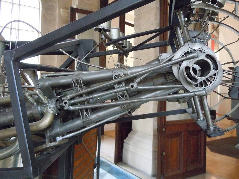
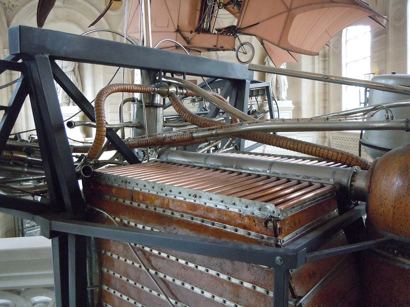
| Left: Avion III in the CNAM museum in Paris: 1897
To maintain control the pilot had to work two foot pedals and six hand cranks, plus the engine controls. It was not a practical control system.
Once again there is no forward vision.
Author's photograph March 2010
|
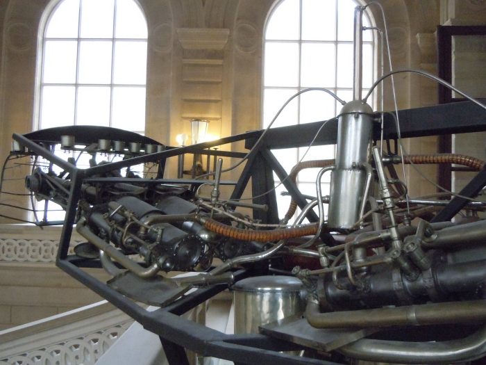 |
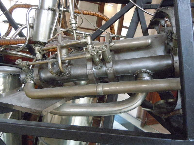
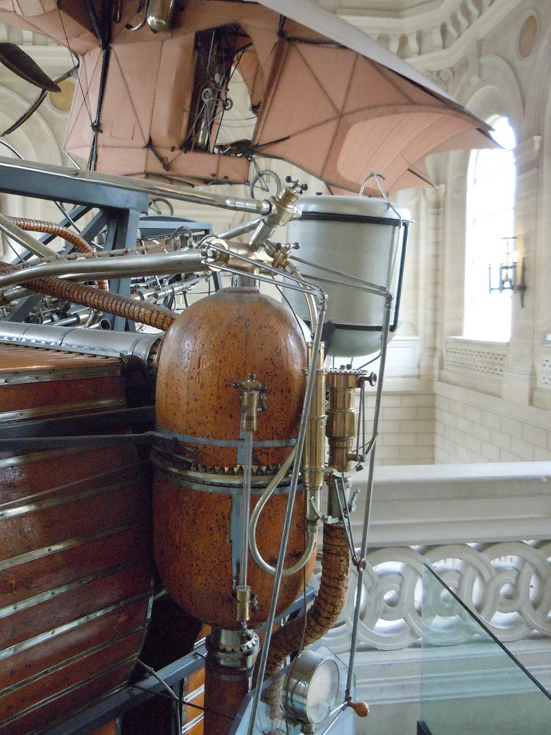
| Left: Replica of Avion III engine installation in the CNAM museum in Paris: 1897
One engine can be seen at the left, and part of the other engine on the right, painted black. The engines appear to be descendents of Stringfellow's engine. The function of the 'silver coffee-pot' on the middle right is currently unknown.
According to Ader the steam was at "eight or nine atmospheres" which corresponds to 118 psi and 132 psi. For some reason there is very little information available on the steam installation; this is odd as you would think it quite famous.
Author's photograph March 2010
|
 |
| Left: Replica of Avion III engine installation in the CNAM museum in Paris: 1897
Two eccentrics driving the valvegear; there are two (presumably) coaxial shafts going into the valvegear cylinder on the left. Note the skeleton structure of the eccentrics, designed to minimise weight.
The two converging tubes behind the eccentric rods are the chassis of the engine, structurally joining the cylinders on left with the crankshaft to the right.
Author's photograph March 2010
|
 |
| Left: Replica of Avion III engine installation in the CNAM museum in Paris: 1897
View shifted left, showing more of the valvegear cylinder, with various pipes running into it.
Author's photograph March 2010
|
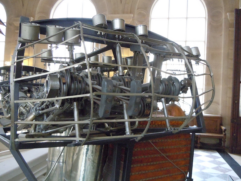 |
| Left: Replica of Avion III engine installation in the CNAM museum in Paris: 1897
View from the outboard end, showing the crankshaft. The silver pots are believed to be gravity lubricators.
The corrugated things are the crankshaft bearings, ribbed for strength with lightness.
Author's photograph March 2010
|
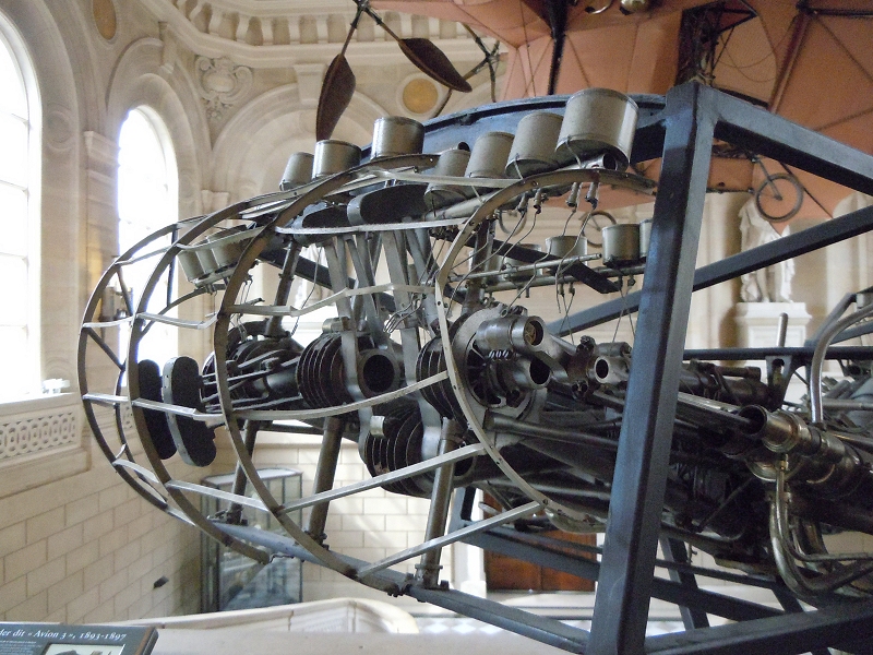 |
| Left: Replica of Avion III engine installation in the CNAM museum in Paris: 1897
The crankshaft on the other side.
Author's photograph March 2010
|
 |
| Left: Replica of Avion III engine installation in the CNAM museum in Paris: 1897
The big box is the boiler. The fuel was alcohol.
Author's photograph March 2010
|
 |
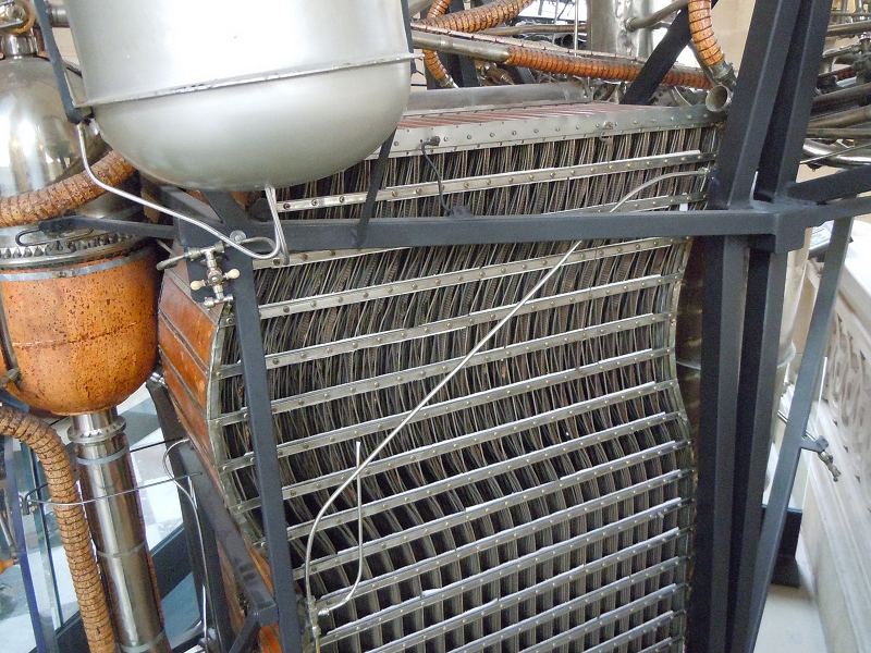
| Left: Replica of Avion III engine installation in the CNAM museum in Paris: 1897
The boiler and auxiliary devices. The brown cylinder may be for storing water or the alcohol fuel. Note it has a level gauge.
Author's photograph March 2010
|
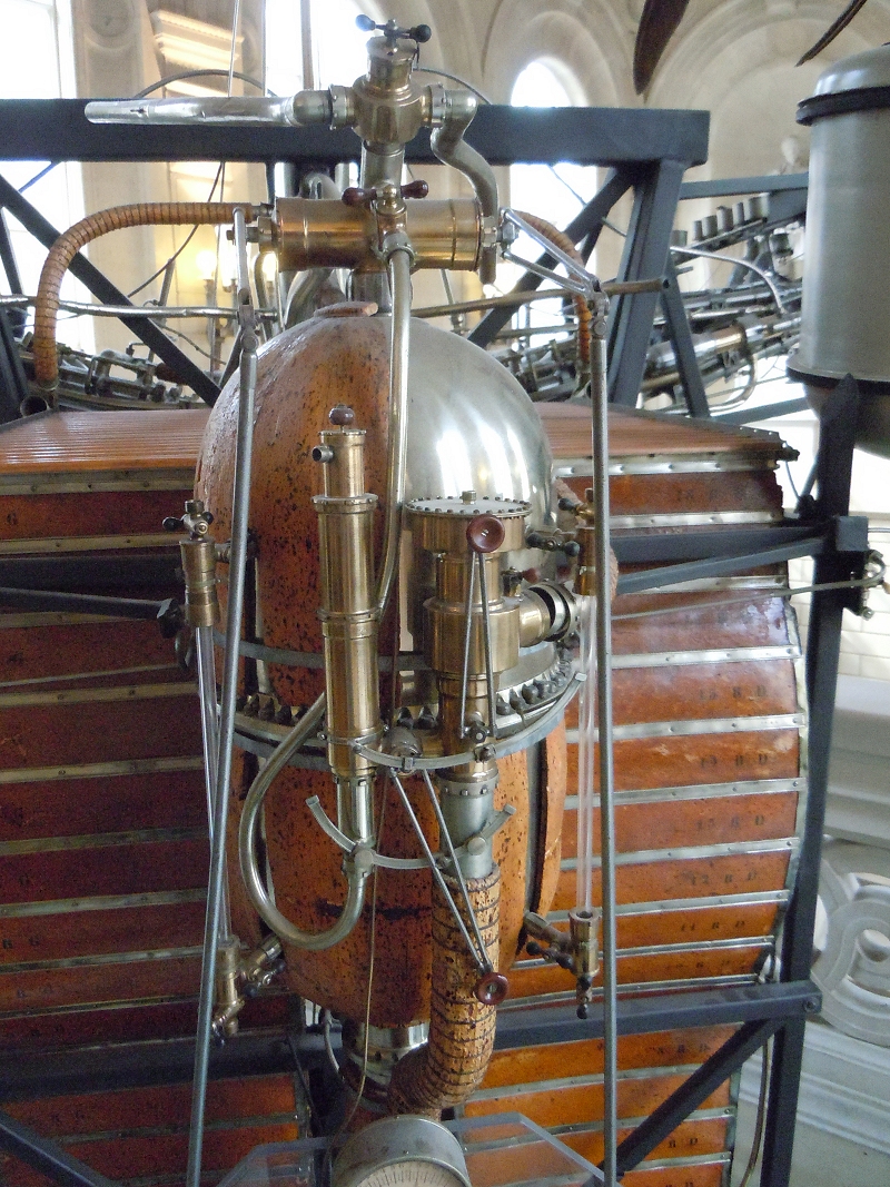 |
| Left: Replica of Avion III engine installation in the CNAM museum in Paris: 1897
The boiler and auxiliary devices. Little of what can be seen here is identifiable. The pipe at centre bottom appears to be insulated by a thin layer of cork held on by wire. Presumably it carried a heated fluid.
There are two control valves with red handles, function unknown.
Author's photograph March 2010
|
 |
| Left: Replica of Avion III engine installation in the CNAM museum in Paris: 1897
The front of the boiler.
Author's photograph March 2010
|
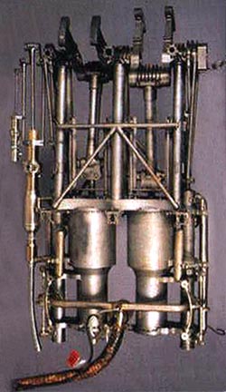
SIR HIRAM MAXIM'S STEAM TESTBED: 1894
Sir Hiram Stevens Maxim (yes, he of the Maxim Gun) built and tested a large steam powered flying machine. On one run this machine generated sufficient lift and thrust to break free of the restraining rails of the test track, at which point the pilot wisely cut the power, as the machine would almost certainly have been uncontrollable. This has never been considered as a piloted aircraft in sustained and controlled flight, but it was undoubtedly a very brave effort.
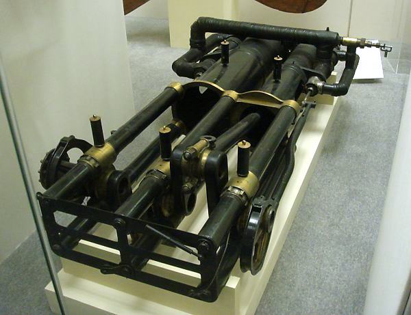 |
| Left: One of the two steam engines of Maxim's flying machine
The flying machine was powered by a pair of two-cylinder compound engines producing 180 HP (134 kW) each, driving two propellors 17.8 feet (5.4 m) in diameter. Once again the engines resemble those of Stringfellow and Ader.
The engine is shown here nestling safely in the Science Museum in London.
Author's photograph
|
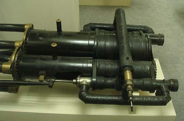 |
| Left: One of the two steam engines of Maxim's flying machine
The high-pressure cylinder is nearer the camera, and has a diameter of 5.05 inches. The low-pressure cylinder is at the rear, and has a diameter of 8 inches. The short cylinder nearest the camera contains the HP valves.
Author's photograph
|
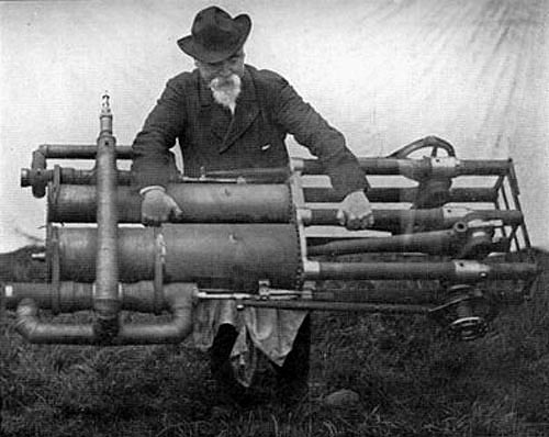 |
| Left: Sir Hiram Maxim demonstrates the lightness of his engine
Note the valves are driven by skeleton eccentrics to save weight.
|
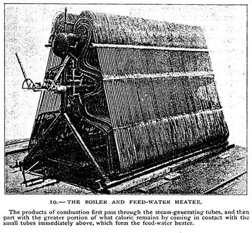 |
| Left: The water-tube boiler for the Maxim engine
The boiler was made by Thornycroft, who had much experience in building lightweight steam machinery for the early destroyers. It was fired by naphtha, and produced steam at 320 psi.
Sir Hiram speaks:
"...I decided that in my first experiments at least I would use a steam-engine. I therefore designed and made a steam-engine and boiler of which Mr. Charles Parsons has since said that, next to the Maxim gun, it developed more energy for its weight than any other heat engine ever made. That was true at the time, but is very wide of the mark now."
(Lecture to the Scottish Aeronautical Society, delivered in Glasgow in November, 1913)
|
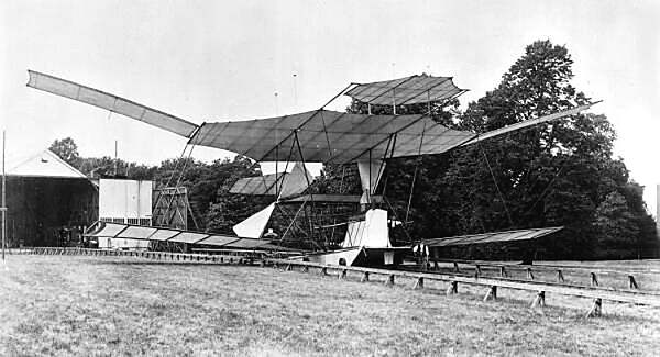 |
| Left: The Maxim aeroplane: 1894
|
STEAM AEROPLANES AFTER THE WRIGHT BROTHERS
THE BRISTOL TRAMP: 1919
The Bristol Tramp was intended to be a steam-turbine driven flying boat. The powerplant was to be two 1500 HP (1120 kW) steam turbines of the Ljungstr�m type, with high-pressure steam provided by flash boilers working in a closed-circuit. See Wikipedia.
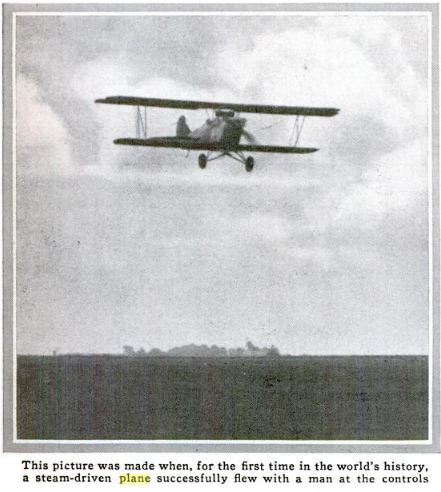
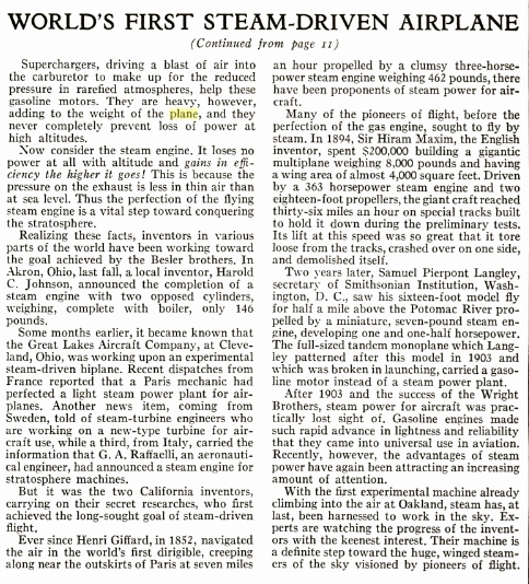
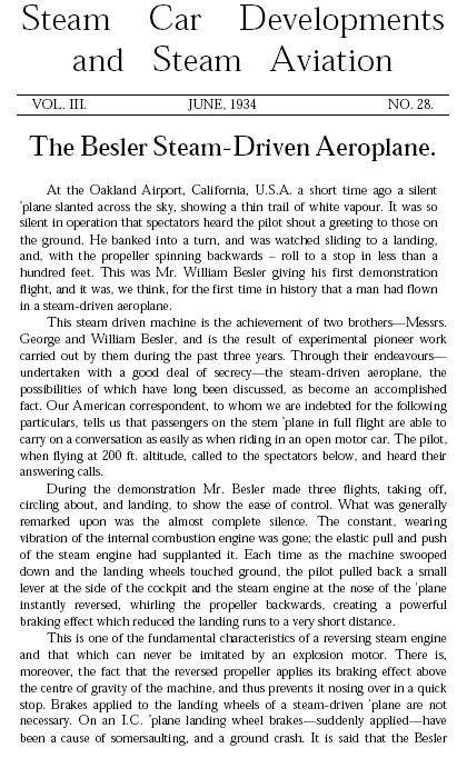
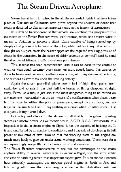
THE BESLER STEAM PLANE: 1933
This is probably the best-known of the steam aeroplanes. The Besler brothers (George D Besler and William J Besler) fitted a steam power plant to a Travelair 2000 biplane at Emeryville, California. It made a demonstration flight on 12th April 1933, over Oakland, California, piloted by William Besler.
A fascinating early film of the demonstration flight, including taxi-ing backwards by reversing the engine, can be seen on YouTube.
Many thanks to Denis Vanbrussel for drawing this to my attention.
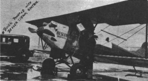 |
| Left: The Besler Steam Plane being fuelled
From "Floyd Clymer's Steam Car Scrapbook" Bonanza Books.
|
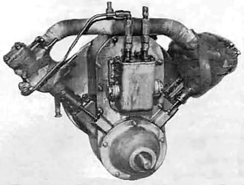 |
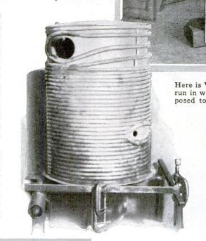
| Left: The Besler two-cylinder steam engine
The engine was a two-cylinder compound in V-configuration; one cylinder ran at high pressure and the other low. It was rated at 90 HP, fed with steam at 1130 psi and 430 degC. It weighed about 500 lbs.
It was designed collaboratively by the Doble Steam Motors Company and the Besler brothers.
|
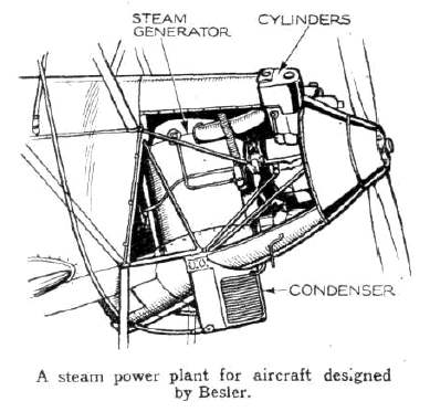 |
| Left: The Besler power plant
Steam was supplied by a coil-tube boiler burning oil fuel, with forced draught provided by a fan. The condenser worked at atmospheric pressure. (ie did not create a vacuum)
The propellor was driven directly at 1350 rpm.
From the British journal "Flight" 30th July 1942; at this date they were probably very pleased to have something to publish that was totally impractical and so of no use to the Germans.
|
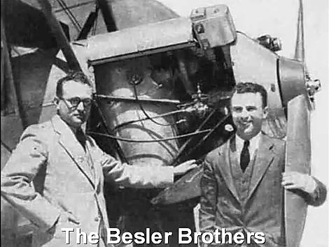 |
| Left: The Besler brothers with the converted plane
The cylindrical steam-generator can be seen between the two men.
|
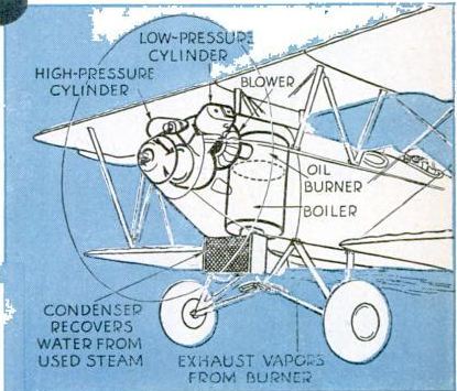 |
| Left: The Besler plane in Popular Science: 1933
There was an article on the Besler plane in the July 1933 issue of Popular Science, which included this diagram.
Source: Popular Science July 1933, pp9 - 11, continued p92
|
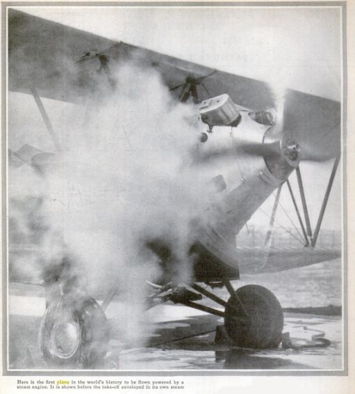 |
| Left: The Besler plane in Popular Science: 1933
The Besler plane wreathed in steam just before takeoff. This does not augur well for the conservation of water.
Source: Popular Science July 1933, pp9 - 11, continued p92
|
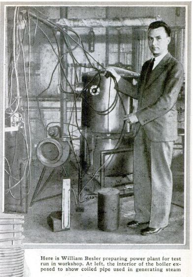 |
| Left: The Besler plane in Popular Science: 1933
William Besler with the steam boiler.
Note the U-tube manometer at bottom left, presumably to measure the pressure given by the air blower.
Source: Popular Science July 1933, pp9 - 11, continued p92
|
 |
| Left: The Besler plane in Popular Science: 1933
Inside the boiler casing.
Source: Popular Science July 1933, pp9 - 11, continued p92
|
 |
| Left: The Besler plane in Popular Science: 1933
The Besler plane in flight.
Source: Popular Science July 1933, pp9 - 11, continued p92
|
<--
 |
| Left: The Besler plane in Popular Science: 1933
The Besler plane in flight.
Source: Popular Science July 1933, pp9 - 11, continued p92
|
-->
 |
| Left: A report on the Besler Steam Plane
From "Steam car Developments and Steam Aviation" No 28, June 1934.
Unfortunately this report is long on waffle but short on technical detail.
|
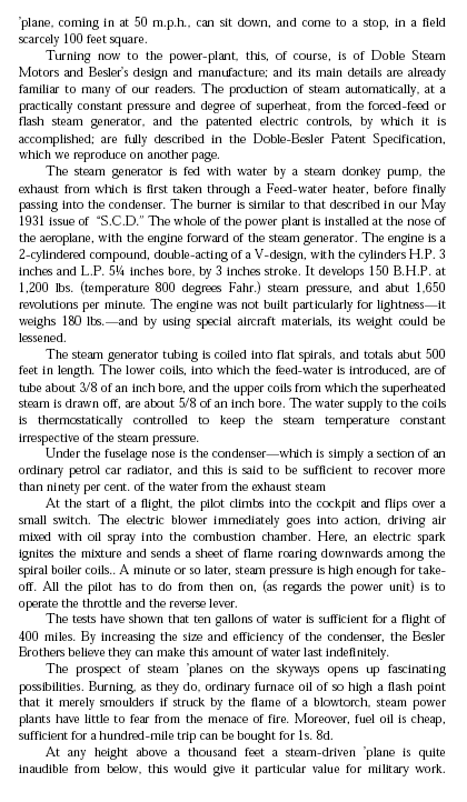 |
| Left: A report on the Besler Steam Plane
Here we learn that the Doble-Besler engine generated 150 BHP with steam at 1200 psi- a healthy power output and an impressively high pressure. Note however that other sources (see above) gave the power output as 90 HP.
It is claimed that the rather small air-cooled condenser could recover more than 90% of the exhaust steam. Given its modest dimensions, I'm not sure that I believe this; even if it was true, a 10% rate of water loss would put a crippling limit on the range of the aeroplane
|
 |
| Left: A report on the Besler Steam Plane
The emphasis on noiseless planes is not as daft as it sounds. In 1934 the main method of detecting aeroplanes was by acoustic location, and effective radar was some years in the future.
|
 |
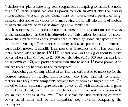
| Left: A report on the Besler Steam Plane
This appears to be a separate article. It makes some odd claims, namely that it is impossible to stall a steam engine in flight; one would have thought it equally impossible to stall an airborne IC engine in the way you might stall a car engine by using too little throttle or too high a gear. Presumably this is nothing to do with aerodynamically stalling the plane.
I see no reason why a steam power plant should be unaffected by atmospheric conditions. I should have though that the thinner air at altitude would affect the performance of both the boiler and the condenser.
Interesting point about being able to reverse the propellor though.
|
 |
| Left: A report on the Besler Steam Plane
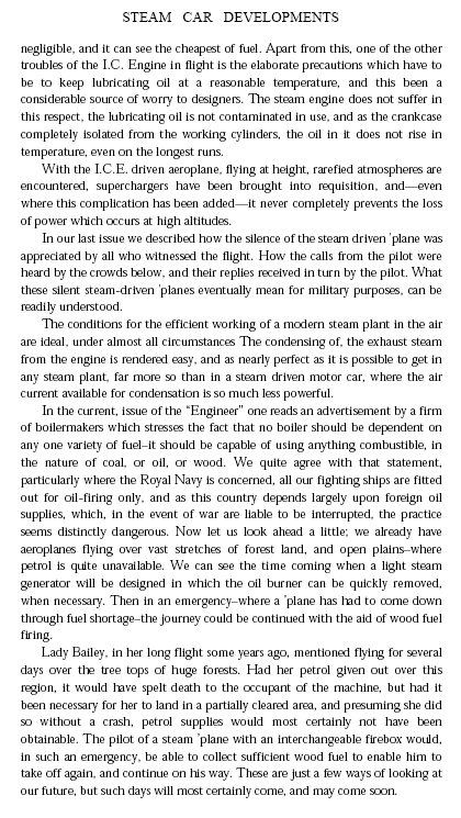
Somehow the idea of making a forced landing and chopping down trees for fuel does not seem too convincing to me. If there are lots of trees, isn't that going to make landing in one piece rather difficult? And surely green wood won't burn very well?
|
THE HUETTNER STEAM PLANE: 1934
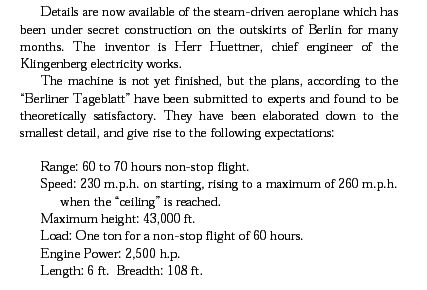 |
| Left: The Huettner Steam Plane
Details from The Daily Telegraph for 16 April 1934, as reproduced in Steam Car Developments and Steam Aviation for June 1934.
I Am Not An Aircraft Designer, but to me these specifications seem highly optimistic.
|
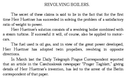 |
| Left: The Huettner Steam Plane
More details from The Daily Telegraph for 16 April 1934; the second half of the extract.
The sad fate of the Berlin correspondent is probably explained by the following fact; in January 1933 Hitler was appointed Chancellor, ie head of the German government. Clearly his rearmament plans at that time included steam aviation...
|
Further details of the Huettner project are proving hard to find, and for that very reason I think it can be safely assumed it was not a success.
Some details of the revolving boiler power-plant can be found on The Rotary Boiler Page.
Wikipedia has a page on steam aeroplanes here.


