There is very little doubt that in almost all circumstances the correct number of wheels for a car is four. That has of course not stopped keen inventors from trying either more or less, and here you see some of the results.
This page confines itself to the unconventional. Goods vehicles with six or more wheels are of course very common. Tracks are not counted as wheels; this matters because there are various vehicles with a mixture of wheels and tracks.
ONE WHEEL
I don't think there is any rational way you could call a vehicle with one wheel a car. The Museum has an extensive collection of monowheels, but very few of them have any form of bodywork and the majority can only carry one person. A possible candidate might be the monowheel tank (preferably as the civilian version).
 |
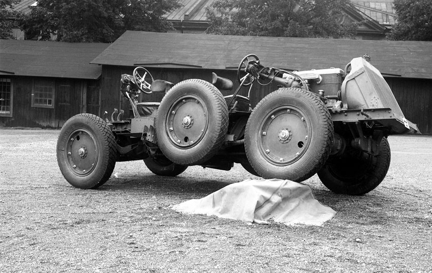
| Left: A civilian version of the monowheel tank: 1933
This design's claim to be a one-wheeled car is somewhat undermined by the two hefty stabiliser wheels at the back. It appears however that these can be raised by a lever once you've got up speed. Other objections are that the steering is by handlebars rather than a steering-wheel, and that it seems to be strictly a one-seater.
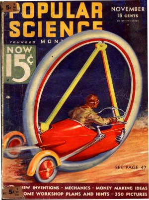
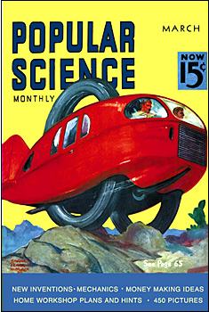
Anyhow, that's the best I can do for the moment, but I suspect that a trawl through the covers of Popular Science and similiar journals would soon throw up something that could claim more plausibly to be a one-wheeled car.
This is an artist's impression and it is extremely unlikely that it was ever built.
|
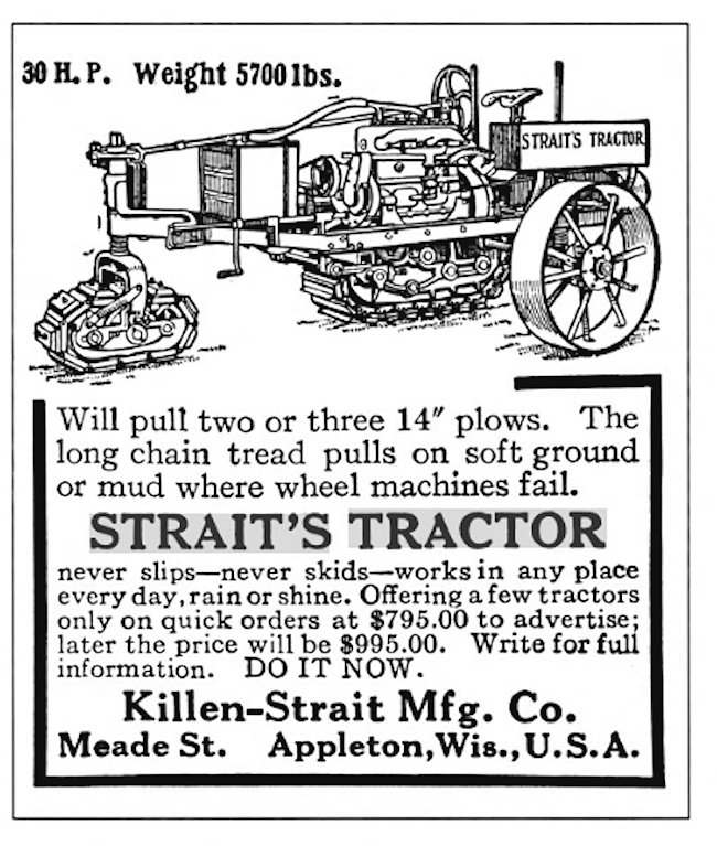 |
| Left: The Killen-Strait tractor: date unknown
I hope we can all agree that this a one-wheeled vehicle, and it is certainly not a monowheel. There may be an excellent agricultural reason for this configuration, but I have no idea what it is. Can anyone help?
I am also unsure of the advantage of steering with the little track; it does not appear to be powered.
Googling "Killen-Strait tractor" gets you a lot on the Killen-Strait Armoured Tractor, built in Britain in 1915, which is often considered to be the first armoured tracked vehicle, rather than this one-wheel farming tractor. The Killen-Strait Armoured Tractor was all-track (including a little one at the front for steering, again) and it has a Wikipedia page.
|
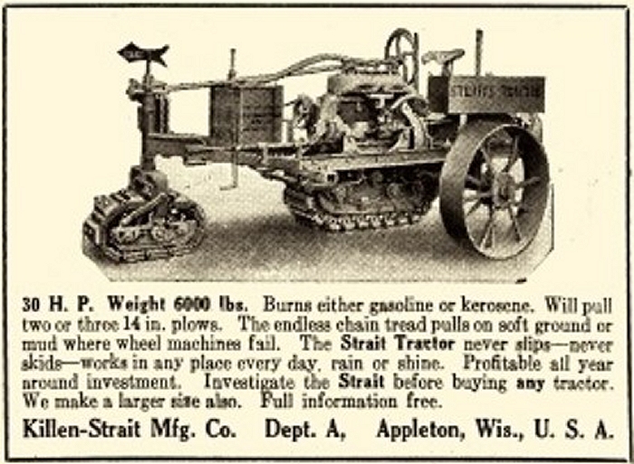 |
| Left: The Killen-Strait tractor: date unknown
This is taken from a photograph, and is clearly the source of the drawing above. I have so far found no other images or info on what is a most interesting machine.
This picture shows a helpful direction arrow on the top of the steerable track. This presumably means that the front track was not visible from the driving position. Steering was by worm and pinion, and so multi-turn; that may have had something to do with it. Research suggests it was a guide to the driver keeping the front track in its furrow.
I wonder if it had that one wheel to save money? Tracks are complicated and expensive to make.
|
Now, the Nwheel Vehicle Game (Mornington Crescent!) depends on what rules you decide to follow. If you don't count tracks as wheels, then:
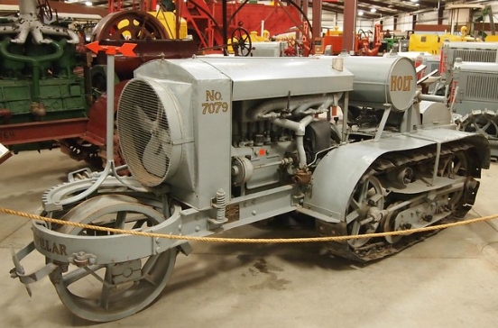 |
| Left: Holt Midget-18 Model-K tractor: 1915
Ignoring the tracks, this is clearly a one-wheel vehicle. This means of steering (one wonders how effective it was) was adopted to avoid the difficulties of steering with just the tracks, which as any tank designer can tell you, involves complicated clutches and differentials.
Note the red directional pointer above the front wheel.
|
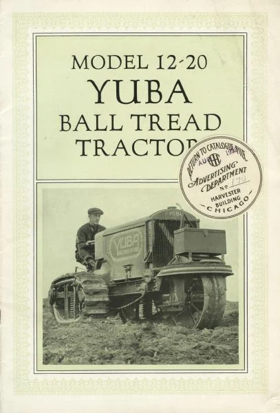 |
| Left: The Yuba Ball Tread 12-20 tractor: date unknown
Like the Holt Midget-18 above, this tractor had twin tracks riding on two rows of large steel balls, instead of pins and rollers. The water-cooled engine ran on petrol (or somewhat heavier 'distillate') and had magneto ignition with Newton Automatic spark advance. '12-20' meant a 20 HP engine with 12 HP available at the drawbar.
You can read the instruction manual here. It gives no clue what 'Ball Tread' refers to, but it seems to mean just the use of ball bearings in the tracks, which is emphasised in the manual. Manufacture of the Yuba ceased in 1921, and by 1931 production of ball-tread tractors ceased completely.
The Ball Tread Co. began building tracked tractors in Detroit in 1912. The tractor shown here is believed to have been the company’s first product. The company also produced an 18-35 model. In 1914, the Yuba Construction Co. of Marysville, California bought out the Ball Tread company and relocated operations to California.
|

2 WHEELS
If we permit ourselves the luxury of two wheels for a car, then we find ourselves with a good number of genuine candidates.
Two-wheeled cars with gyroscopes are dealt with here and here.
Two-wheeled cars without gyroscopes are dealt with on the 2-wheeled car page. These cars all have one wheel at the front and one at the back.
If you have two wheels side-by-side then you have a diwheel.
 |
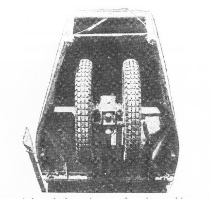
| Left: The Bryant diwheel: 1938
The Museum has a large collection of diwheels, but this artist's impression is the nearest it gets to an actual car. This design (which I am quite sure no one attempted to build) certainly has bodywork and clearly seats at least two people; probably more judging by the windows halfway along the cabin. Note the rudder at the back for high-speed steering. You can read more this vehicle on this page.
It is far from clear how you would change a wheel should you suffer a puncture. This design has not been tested for practicality.
|
 |
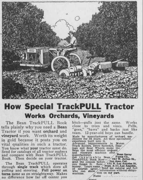
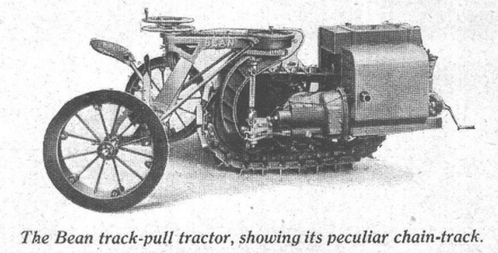
| Left: The Bean Trackpull tractor: 1918
The Bean Trackpull had a single central track. You can see the advantage; if you can make it work you've immediately eliminated dozens of track parts. There are two steering-wheels; the top on does the actual steering by swivelling the rear wheel assembly (how effective was that?) The lower wheel apparently operated the clutch. The engine was rated at 6 to 10 HP. According to their adverts, Bean claimed this machine was the equivalent of six horses. The Bean was manufactured in San Jose, California.
Note the Power-Takeoff (PTO) pulley just to the right of the radiator. How do you change gear?
On the basis of we-don't-count-tracks-here this is a two-wheeled vehicle.
There is more info here.
|
 |
| Left: The Bean Trackpull tractor: 1918
The Trackpull was aimed at orchards and vineyards; it could move between trees planted closely together. The picture shows how the rear wheels could be set at 90 degrees to the track, so the machine could turn around in its own length.
|
 |
| Left: The Bean Trackpull tractor: 1918
This shows the side where the engine was mounted. The other side of the vehicle carries only the radiator, which sounds like a rather unbalanced situation.
Source unknown
|
 |
| Left: The Bean Trackpull tractor: 1918
The Bean is Best.
|
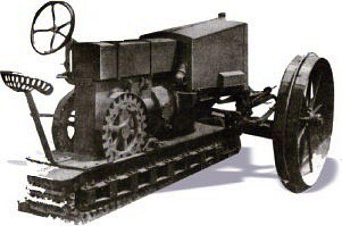 |
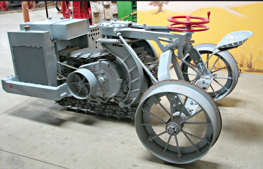
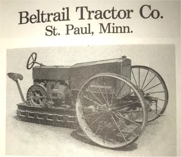
| Left: The Beltrail Model-B 12-20 tractor: 1917 to 1920
For a while this machine has rested in the 'one-wheel' section, but it is now clear that there is a wheel on each side at the front, so it is moved here.
This machine had the unusual set-up of just one track running underneath the vehicle, rather like the Bean Trackpull just above. At first sight looks as if it might be another case of just one wheel plus tracks, like the Killen-Strait tractor above, but this is probably the result of some overenthusiastic retouching. There were two wheels at the front.
|
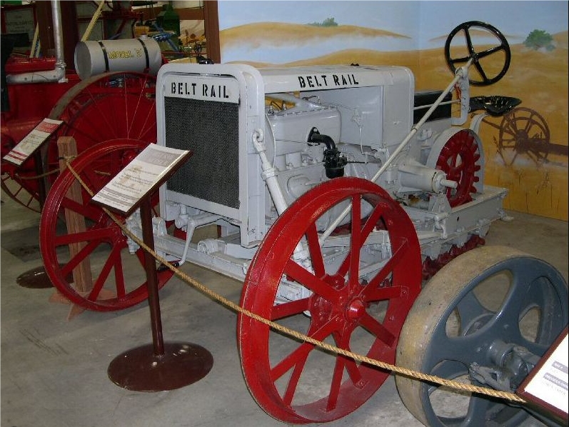 |
| Left: The Beltrail Model-B 12-20 tractor: 1917 to 1920
This photograph of a Beltrail tractor in an unknown museum proves that there were indeed two wheels at the front.
The thing sticking out to the left of the red sprocket appears to be a power take-off.
The Beltrail Tractor Co. was based in St Paul, Minnesota, USA and made tractors from at least 1917 to 1920.
My grateful thanks to Steven McDonald for drawing this picture to my attention.
|
 |
| Left: The Beltrail Model-B 12-20 tractor: 1917 to 1920
This appears to be a manufacturer's photograph. It demonstrates that the hefty track mechanism was driven by a sprocket on each side.
|
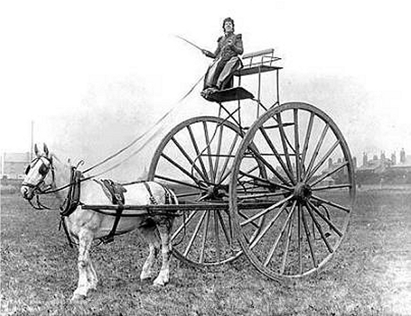 |
| Left: A most peculiar cart: 1917 to 1920
This picture is wholly mysterious. An image search has yielded nothing.
It is clearly a less than practical vehicle; how do you get up to the seat, especially in a long (Victorian?) skirt? Perhaps there is a ladder just out of shot.
It looks like falling off it might not be survivable.
So far as I can tell it is a genuine picture but it might be Photoshop. Assuming it's real I can only suppose it was built as some sort of joke, or possibly to win a bet.
|
3 WHEELS
There have been a huge number of three-wheeled cars. Here only a few especially significant or odd designs are displayed.
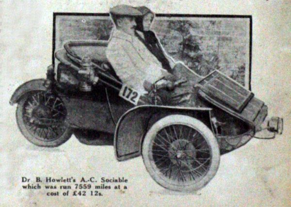
3 WHEELS: A C SOCIABLE: 1911
 |
| Left: The A C Sociable: 1907-14
The A C Sociable was a very successful early three-wheeler. It adopted what is usually considered to be the most stable configuration- two wheels in front and one at the back, like the Morgan. Driver and passenger sat side-by-side, making conversation easier, and so this was called the 'sociable' configuration. The original name was Auto Carriers Ltd.
It had a 5.5 HP 631 cc air-cooled side-valve single-cylinder engine, and a two-speed epicyclic gearbox, with no reverse gear; final drive was by chain to the rear wheel. The front axle was solid with semi-elliptic leaf springs, while the single rear wheel had dual quarter-elliptic leaf springs. Brakes operated on the transmission and the rear wheel. The wheelbase was 70 inches.
This model has a luggage-box on the rear body.
|
 |
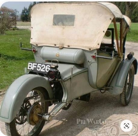
| Left: The A C Sociable: 1907-14
An A C Sociable from the other side.
The A C Sociable has an entry on the A C Wikipedia page.
|
 |
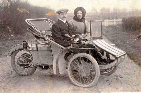
| Left: The A C Sociable: 1907-14
Economical motoring. Date of picture unknown.
|
 |
| Left: The A C Sociable: 1907-14
With the hood up. Location and date of picture unknown. This AC Sociable dates from 1912.
|
 |
| Left: The A C Sociable: 1907-14
Location and date of picture unknown.
|
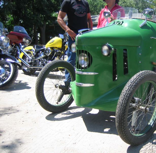 |
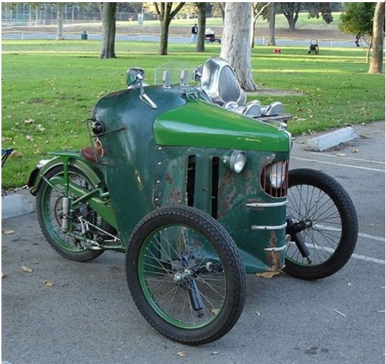
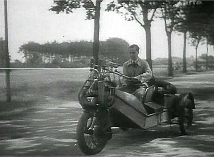
| Left: Customised French tricycle: 195?
This French tricycle is vaguely reminiscent of a tractor, with its headlight peering out from between protective bars.
Grateful thanks to Rémi Démoulin for the identification of this machine as a conversion of a Motobecane d45 motorbike. These bikes were popular in France after WW2.
Photographed at the annual Griffith Park Sidecar Rally, year unknown.
|
 |
| Left: Customised French tricycle: 195?
This looks like a lot of vehicle to carry just one person.
|
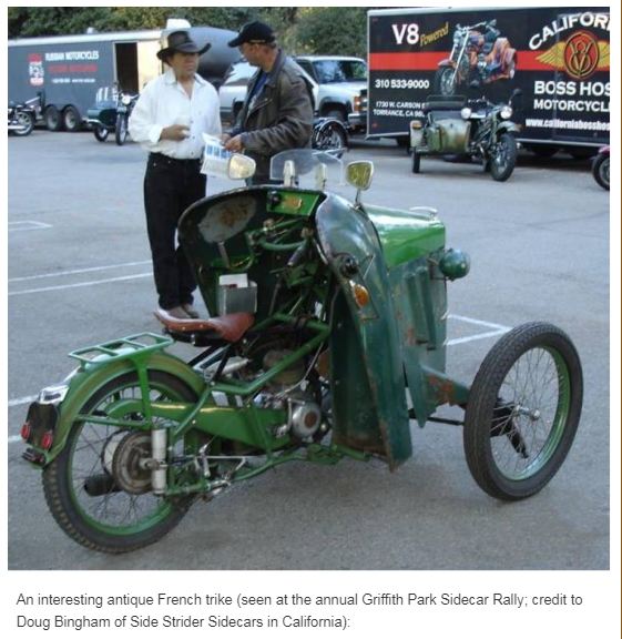 |
| Left: Customised French tricycle: 195?
The parent Motobecane d45 motor bike was identified from the distinctive rear suspension.
|
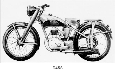 |
| Left: Motobecane d45s motorcycle: 195?
The s-suffix denoted an improved rear suspension.
There is more information here.
|
GERMAN CYKLON THREE-WHEELER
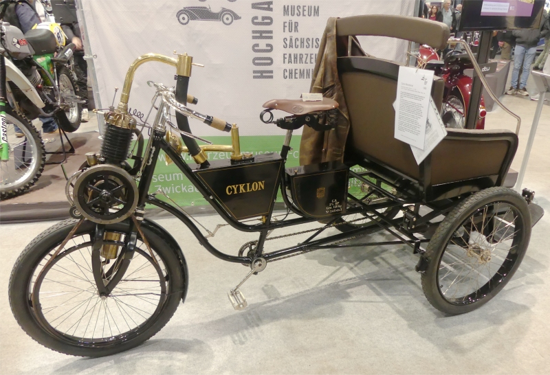 |
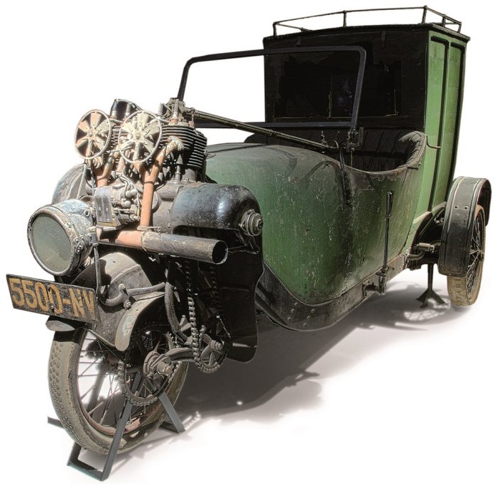
| Left: Cyklon tricycle: 1899
This early machine was the forerunner of the Cyklonette described below. It was designed by Franz Louis Hüttel; (1862-??) he went on to design both the Cyklonette and the Phänomobil. (also below) The front wheel is driven by a leather-covered rope; this can be slackened by a lever on the right side of the handle bars to act as a clutch. Somehow leather-covered rope doesn't sound as if it would be free from slipping.
The 4-stroke engine has an automatic inlet valve. The carburettor is of the surface type; the induction stroke pulls air out of the top of the fuel tank, through an elegantly curved pipe leading to a brass drum with 2 handles; presumably a throttle, and a mixture control which admitted extra air. Surface carburettors relied on simple evaporation, rather than atomising nozzles, and were not very effective; they were essentially extinct by 1904. Ignition is powered by a battery in the box below the seat and behind the fuel tank. Another curved pipe leads down to the top of the engine cylinder, the automatic inlet valve being inside it. There is pedal drive to the rear wheels by a block chain.
There are some biographical details of Franz Hüttel here.
|
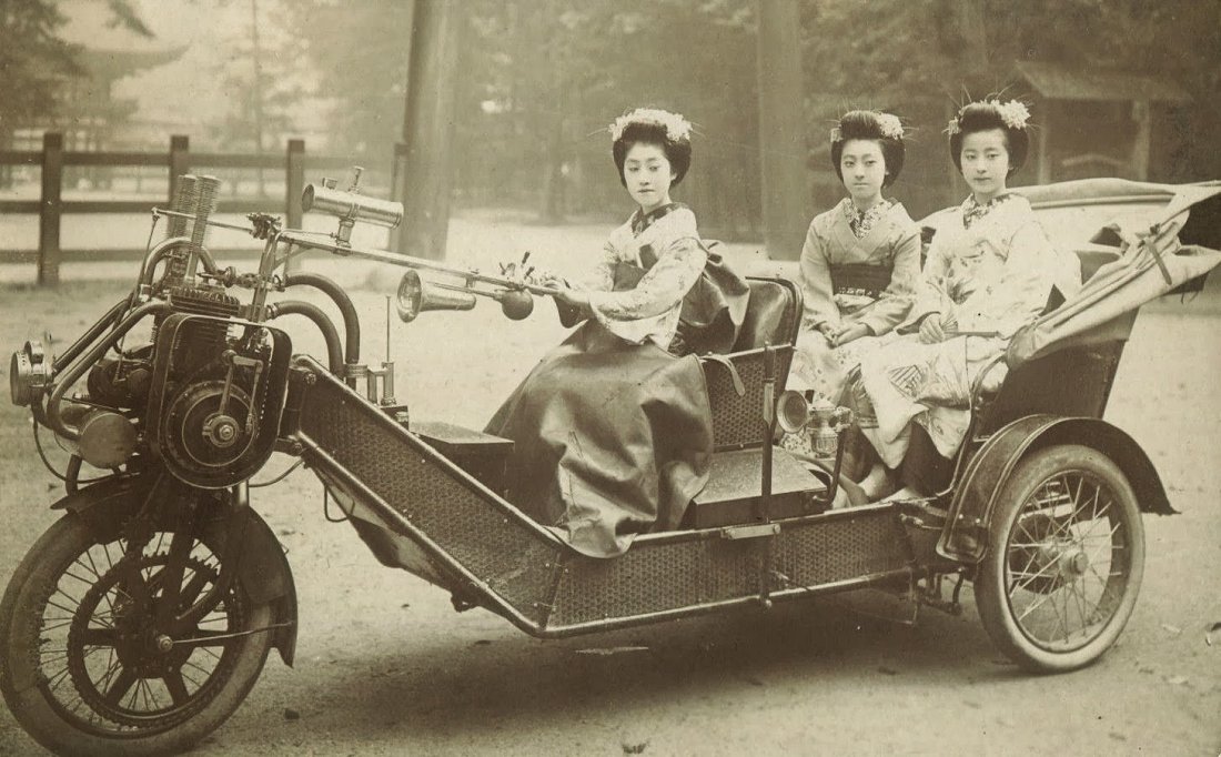 |
| Left: Cyklonette three-wheeler: circa 1910?
This beautiful image was sent to me by one of my correspondents. Three Japanese ladies sit in a remarkable three-wheeled vehicle, now identified as a German Cyklonette. A few thousand of these vehicles were produced between 1907 and 1927.
The engine is mounted over the front wheel and drives it by a chain. Clearly the whole thing is swivelled by the tiller, which must have been hard work. Given the distance between the tiller and the pivot the turning circle must have been rather large. The cylinder on top of the tiller looks as if it is a telescopic sight for accurately aiming the vehicle, but it is actually a lubricating oil tank.
Note the (presumably waterproof) cover over the legs of the driver.
|
There appear to be two exhaust pipes leading to a cylindrical silencer under the headlight, and on top there are two tall pillars that appear to have springs around them; they are probably automatic inlet valves. This suggested a two-cylinder in-line engine, and it is now confirmed that it was a 1290 cc twin in-line unit.
There are two pipes to the right of the engine that look as if they are for water-cooling, but the engine barrel is finned for air-cooling. There is a rod on the left side of the engine that looks as if it connects to a magneto (on its side) and probably controlled the ignition advance/retard.
There is more information here and here.
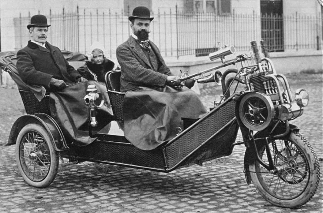 |
| Left: A Cyklonette: date unknown
This looks like the same model as the machine above carrying the three Japanse ladies.
The gent on the left looks like the archetypal Doctor Watson. Could that be Mr Holmes on the right, disguised with a beard?
Once again there are covers over the legs of the occupants.
|
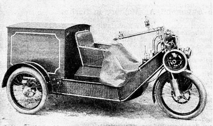 |
| Left: A Cyklonette built for postal delivery work: date unknown
|
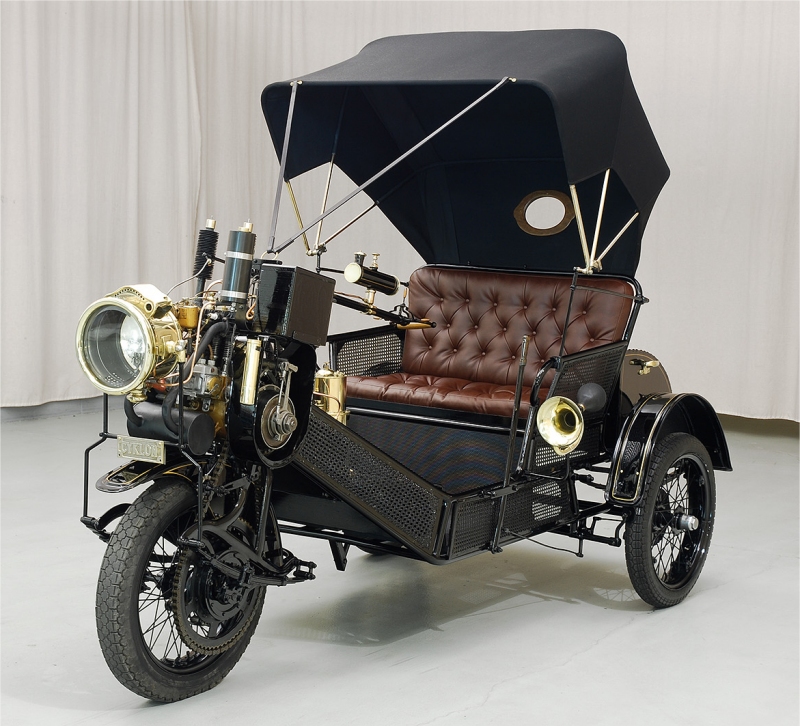 |
| Left: Cyklon Cyklonette preserved: 1930
The location is unknown.
|
 |
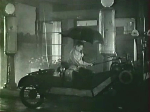
| Left: Cyklon Cyklonette 3-wheeler from Berlin, out in the country: 1930
Until now this machine was billed as a Phanomobil. It looks very similiar to the machine in Japan. (above) It has a chain drive on the left side of the front wheel, just like the Phanomobil. I suggest it would have fooled anybody.
However, I am informed it is actually a Cyklon Cyklonette, made from 1904 to 1924. This is a still from the film Die Drei von der Tankstelle (1930) meaning "The Three from the Gas-Station". There is a brief Wikipedia page.
Of the film: "The gas station attendant Heinz Rühmann from the gas station Kuckuck dedicates himself to a three-wheeled cyclonette. This economical vehicle was built in Berlin between 1904 and 1924".
Many thanks to Nils Moh for pointing out the error and providing the information.
|
 |
| Left: Cyklon Cyklonette 3-wheeler: 1930
This is another still from the film, presumably set at the Gas-Station of the film title.
|
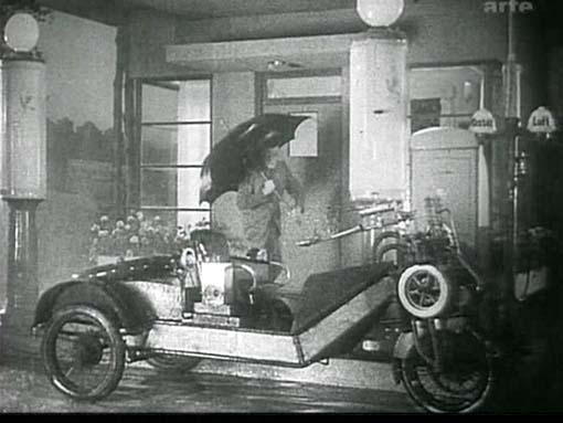 |
| Left: Cyklon Cyklonette 3-wheeler: 1930
This still gives a better picture of the Cyklonette.
|
GERMAN PHANOMOBIL THREE-WHEELER
The Phanomobil was a leter development of the Cyklonette.
 |
| Left: Phanomobil van: 1912
Phanomobils were produced in many forms, including fire engines and carrier-pigeon transports. This delivery van is at the Louwman Museum at The Hague in Holland.
This model had a four-cylinder engine; note the two fans, more shrouding of the drive-chain, and a sideways-firing exhaust that must have annoyed people, not least because the exhaust from the cylinders appears to go straight into it without any form of silencer. There are two spark plugs per cylinder, driven by the magneto sitting just above the exhaust pipe.
Also, the two tall pillars (inlet valves?) visible on the picture above and below seem to be missing.
|
 |
| Left: A Phanomobil fire engine: date unknown
There is an excellent site describing the reconstruction of a Phanomobil here.
|
 |
| Left: A 1912 Phanomobil in a New Zealand museum
Like the Phanomobil van above, there are two cooling fans.
|
GERMAN WALMOBIL THREE-WHEELER
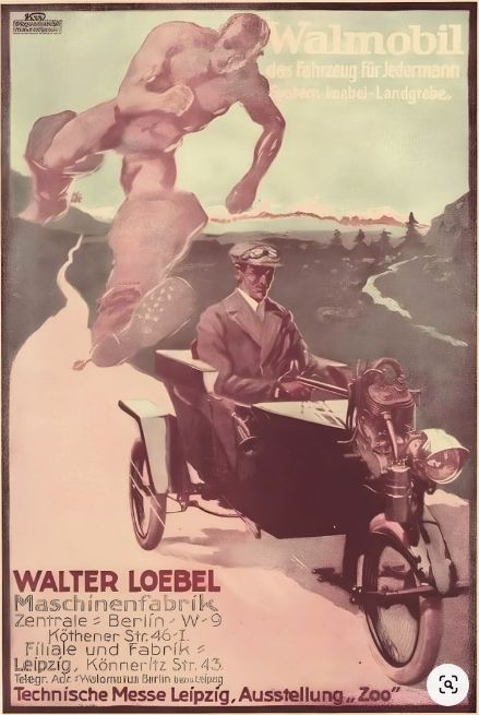 |
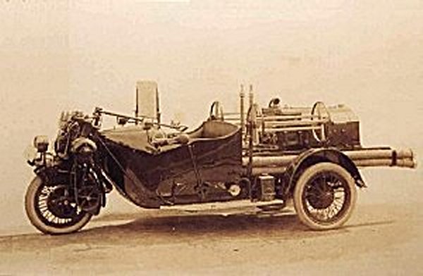
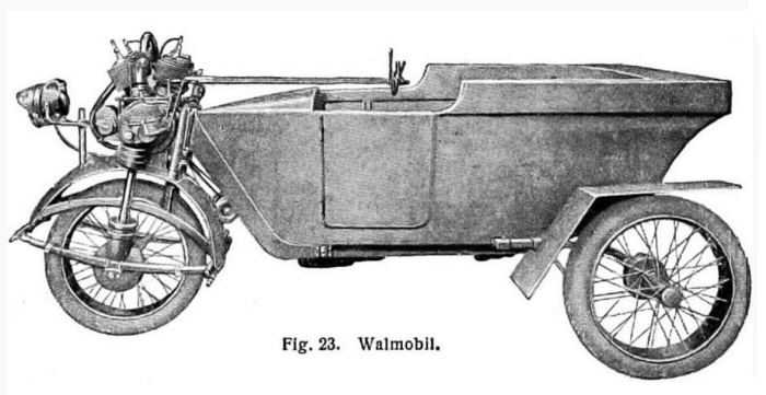
| Left: Advert for Walmobil three-wheeler: 1919-21
The Walmobil looks very like the Cyklonette and the Phanmobile, having a small V-twin engine mounted above a tiller-steered front wheel, but is rather smaller and only seats one. It manufactured by Walter Loebel Maschinenfabrik, of Leipzig & Dresden, but was only in production from 1919 to 1921, which suggests it was pretty much unsuccessful, very likely because of the single seat; at least with a motorbike you can take a pillion passenger.
Walmobil is German for Whalemobile, which seems like a highly inappropriate name for such a small vehicle. Was some sort of irony intended? If so, possibly not the best way to attract customers.
The vehicle was a collaboration between Walter Loebel and E Landgrebe. The chassis came from Loebel and the engine and cardan drive from Landgrebe.
I assume the advert is making some reference to seven-league boots.
There is some more info here.
The Walmobil has a brief Wikipedia page.
|
 |
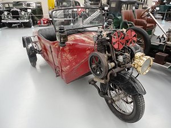
| Left: Walmobil three-wheeler: 1919-21
This picture makes it clear that the front wheel was driven by a telescopic cardan shaft, and unusually has leaf-spring suspension. The steering looks like it might be a simple tiller arrangement, but there seems to be something like a half steering-wheel at the inboard end.
The engine was a V-twin four-stroke with a displacement of 770cc and a power output of 6 to 7 HP.
Both rear wheels had cable actuated drum brakes.
No examples are known to survive.
|
JACKSON 3-WHEELER: 1910
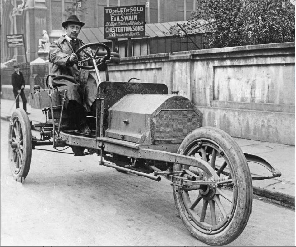 |
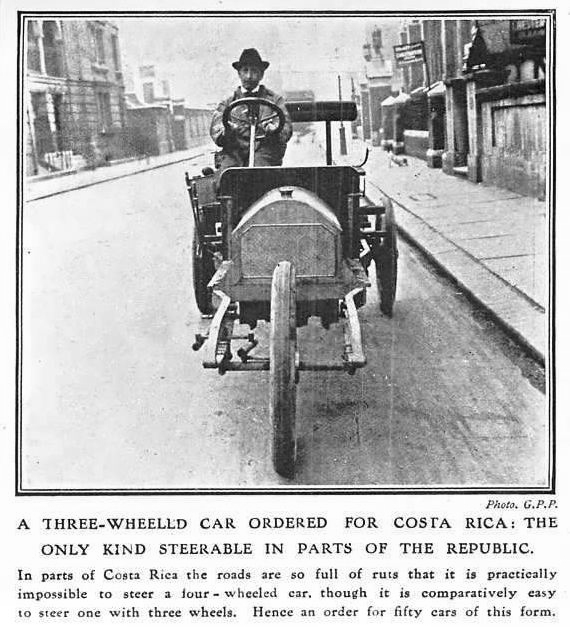
| Left: Jackson three-wheeler: 1910
This car has now been identified by Paul Dunlop as a three-wheeler made by Robert Reynold Jackson & Co Ltd in Notting Hill, London. Fifty of these cars were ordered for use in Costa Rica, where the unmade roads were so deeply rutted it was impossible to steer a car as the front wheels could not swivel. The idea was that the front wheel would travel on the ground between the two ruts and so be able to steer. It has not yet been confirmed that the cars were either made or successfully delivered.
The vehicle was considered unusual enough to attract some attention in British and German periodicals in 1910. Normally Jackson made conventional four-wheel cars, often with parts imported from De Dion in France.
The signboard in the background carries the address '26 High St, Notting Hill Gate', presumably close to the location of the Jackson factory.
The Jackson Company has a page in Graces Guide.
Mr Jackson also has a bio page in Graces Guide.
|
 |
| Left: Jackson three-wheeler: 1910
Another view at the same location.
Robert Reynold Jackson (1871-1947) was born in Ipswich, Suffolk. He first appears in the motor industry in 1900 as the secretary of the Yorkshire Motor Car Manufacturing Co in Bradford. In 1900 he moved to London and imported American cars. By 1903 he had established R. Reynold Jackson & Company. and was manufacturing cars under his own name, probably constructed of parts imported from Lacoste & Battmann, and using De Dion-Bouton engines. Jackson produced some strange cars with unconventional single-cylinder long-stroke engines– so long that the driver had almost to peer around the bonnet– such as the 1909 Black Demon racer with engine dimensions of 104 x 213 mm under a slipper-shaped bonnet coming to a sharp point. Attempts by the Museum Staff to obtain a picture have so far failed. Can anyone help?
Otherwise, the company produced quite normal vehicles: photos of a 1907 dog-cart with De Dion power and a 1909 doctor’s car with a four-cylinder Aster engine were typical products for the time.
Image source: Unidentified magazine
|
3 WHEELS: THE TSAR TANK: 1915
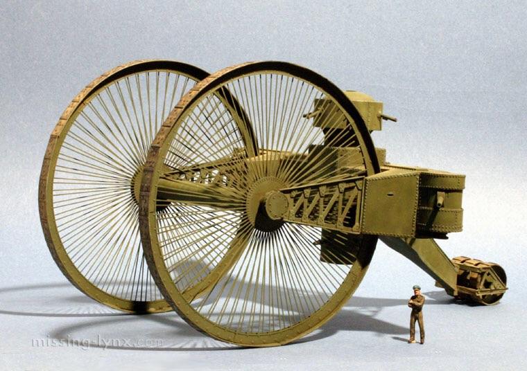 |
| Left: The Tsar tank: 1915
The Tsar tank was probably the biggest three-wheeler ever built. It was prototyped by Imperial Russia, but proved wholly impractical.
This image (I am not sure if it is a model or a rendering) gives a much clearer view of the Tsar-tank's construction than the few photographs that exist. There was a circular turret on top of the main body; it appears to have four guns at 90-degree spacing, so presumably did not traverse. The turret is too small to hold a decent-sized gun, and the field of fire is restricted as the turret is below the top of the front wheels. There is also a turret with at least one gun underneath the main body, with an even more restricted field of fire, and two further guns mounted in sponsons on each side.
The rear wheel, or roller, looks as if it may be divided in three, so technically you could call it a five-wheel vehicle. I think it's clear however, that this is basically a three-wheeler.
There is more on the Tsar tank on the unusual tanks page.
|
3 WHEELS: HARPER RUNABOUT: 1921
The Harper Runabout was developed by Robert O Harper, and manufactured by Avro produced from 1921 to 1926. (Around this time Avro were experimenting with two-wheeled cars)
The Harper Runabout has a Wikipedia page but it has little information.
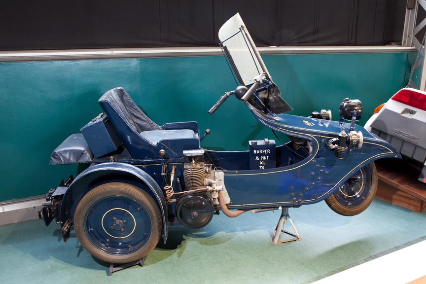 |
| Left: The Harper runabout: 1921-24
The engine was a single-cylinder two-stroke Villiers of 269cc, which developed 2.5 HP, and drove the rear wheels by chain, via a three-speed gearbox. Starting was accomplished by a pull-up lever on the left hand side of the driver, which could be operated from a sitting position. This lever also functioned as a ratchet hand brake.
Science Museum collection.
|
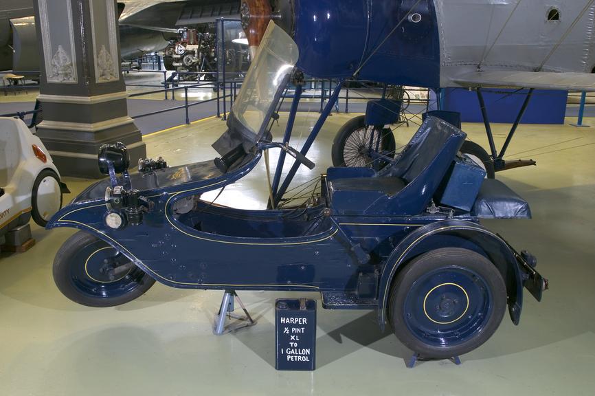 |
| Left: The Harper runabout: 1921-24
There were quarter-elliptical springs on all three wheels, which were of pressed steel. Remarkably for the time, there were disc brakes on all three wheels. It was capable of an economical 100 mpg running at 40 mph.
A common complaint was that the Harper looked a bit too much like a bath chair. (a contemporary invalid carriage)
A total of about 500 machines were produced. This example from 1921 is in the Science Museum collection.
|
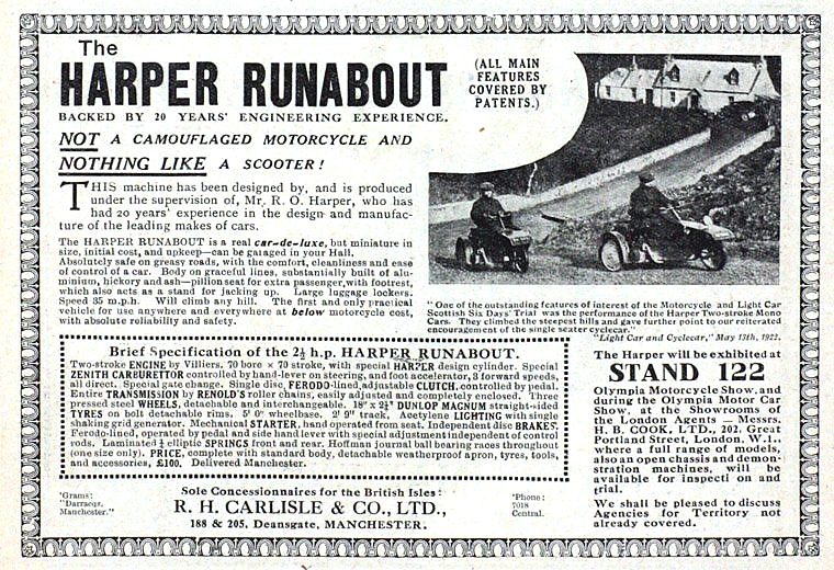 |
| Left: Advert for The Harper runabout
The 'Brief Specification' gives some more technical details of the Harper. Note the acetylene lighting with an intriguing 'shaking grid generator'. I would like to know more about that... but Google is silent on the subject.
And it is NOT a camouflaged motorcycle! Definitely not!
|
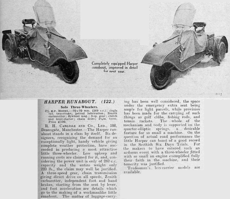 |
| Left: The Harper runabout
This seems to be some sort of entry in a trade catalogue rather than an impartial article.
The 'emergency extra seat', which somehow does not sound too alluring, allowed a passenger to sit behind the driver, facing backwards.
|
3 WHEELS: THE SCOTT SOCIABLE: 1921-25
The Scott Sociable was a very odd sort of three-wheeled car manufactured from 1921 to 1925 by the Scott Autocar Company of Bradford, Yorkshire. This was an offshoot of the well-known and respected Scott Motorcycle Company.
In the course of World War I Alfred Scott developed sidecar machine gun carriers. They were not very successful. After the war he tried a similiar configuration for civilian transport. There emerged a highly asymmetrical three-wheel car with two wheels in line, with a third wheel out to the side and slightly behind the other rear wheel. (Overcoming the puncture drawback noted just above), though that was not the reason)The configuration resembled that of a motorcycle and sidecar combination, but looked very wrong. It looked just like a car with a wheel missing, and apparently handled like one. It was originally announced in 1916 as the Sociable, but production was postponed until 1921. About 200 were made before production stopped in 1924. The cost of a complete Sociable was £273 in 1921, falling to £135 by 1924.
Driver and passenger sat side-by-side; and this was called the 'sociable' configuration.
 |
| Left: The Scott Sociable: 1921-25
This picture demonstrates all too clearly that the Scott Sociable just looked wrong, as if it was poised on the point of falling on its nose.
The Sociable had a triangulated tubular steel frame, and a proper steering wheel acting by rack and pinion on the front wheel. It was powered the Scott Company's own water-cooled 578 cc twin-cylinder two-stroke engine driving through a three-speed gearbox to the offside rear wheel only, by shaft; there was no differential, and no reverse gear. It has been recorded that turning was dangerous at speed; I'll bet it was.
There are many, many, three-wheeled vehicles in the world. This may be the oddest.
|
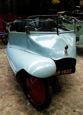 |
| Left: The Scott Sociable: 1922
This Scott clearly dates from 1922.
According to Timothy Jacobs, author of Lemons- The World's Worst Cars, "It had some of the characteristics of a motorcycle-and-sidecar arrangement, but without the flexibility, and could be extraordinarily treacherous to drive." I believe it.
|
3 WHEELS: VINCENT BANTAM
The well-known motorcycle manufacturers Vincent produced a not very successful three-wheeler.
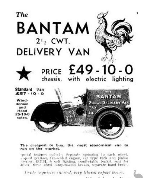 |
| Left: The : 1922
In 1932 the Vincent Bantam was first introduced: this was Vincent's first 3-wheeler; their main products were motorcycles, including the famous Vincent Black Shadow. It was powered by a 293cc SV JAP or a 250cc Villiers engine, and was a 2.5 cwt delivery van with a car seat and steering wheel rather than a motorcycle saddle and handlebars. The Bantam was priced at £57-10-0 with a windscreen and hood available for an additional £5-10-0.
Production ended in 1936.
Apologies for poor image quality- this seems to be the only picture of a Bantam that exists. The text at the bottom is just about legible with a bit of computer enhancement:
"Special features including: Separate springing to each wheel, ? speed gearbox, fan-cooled engine, car-type rack-and-pinion steering, BTH (British Thomson-Houston) 6 Volt lighting, comfortable bucket seat for driver, three-wheel compensated brakes, separate hand brake."
|
3 WHEELS: BSA THREE-WHEELERS
BSA were well-known bicycle manufacturers who made many attempts to break into the motorcar industry. They produced a not very successful three-wheeler.
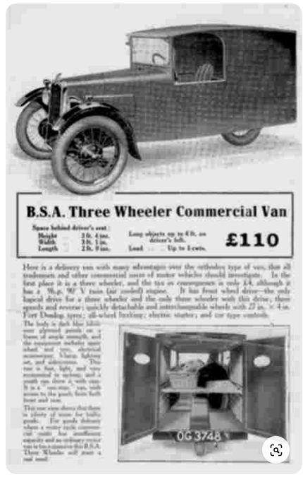 |
| Left: The BSA 3-wheel van: 1931
Unfortunately the text here is mostly illegible even with 'computer enhancement' as it use to be called. It is however possible to determine that had an air-cooled V-twin engine. It claims to be the only three-wheeler that drove both front wheels at that time. (Others like Morgan came later) More squinting at the text reveals it had all-wheel braking and an electric starter, and the annual tax was only £4.
Unfortunately it was not a sales success.
Note that a three-wheel van with a single wheel at the rear has an unfortunate intrusion into the load space.
There is more information on BSA cars in general in Wikipedia.
|
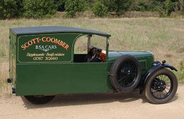 |
| Left: The BSA 3-wheel van: 1931
This is not a preserved BSA van (none are known to exist) but a 're-creation' what ever that means. Anyway, it looks very nice.
Source unknown- found on the Interwebs.
|
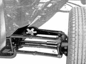 |
| Left: The BSA 3-wheel van: 1931
A major problem with front-wheel drive is the need for the front wheels to swivel while power is being transmittted to them. This requires a Constant-Velocity joint, ie one where the angular velocity does not vary with rotation. A single Hooke joint gives variation amd is unworkable, but two in series can cancel out the variation. A later deveopment was the more compact Birfield joint which is more compact and efficent. The Birfield joint was developed by Birfield Industries and was widely used with the development of front-wheel drive cars such as the Mini.
The BSA used two Hooke joints, one inboard and one outboard. (by the wheel) Note the two leaf springs, and the star-shaped adjuster for the friction damper.
Source unknown- found on the Interwebs.
|
3 WHEELS: THE GOLIATH PIONIER
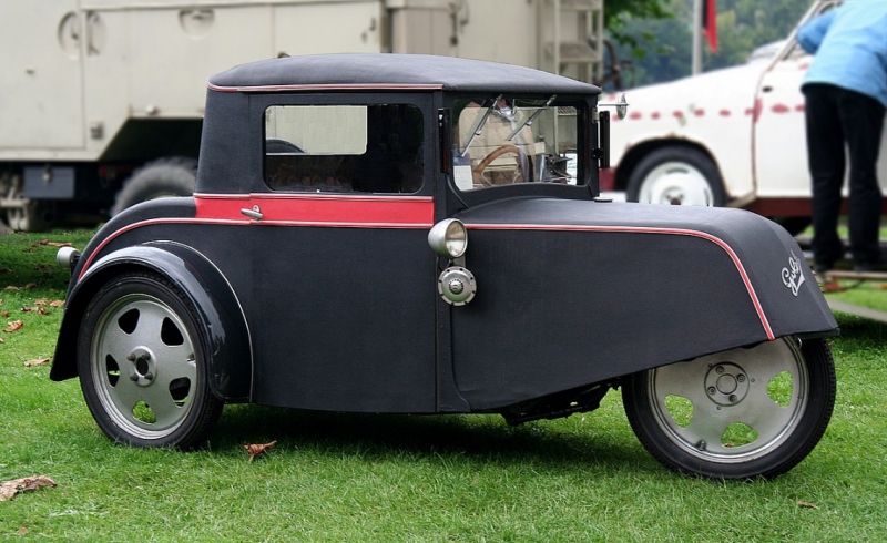 |
| Left: The Goliath Pionier: 1931-34
The very neat Goliath Pionier was manufactured by Goliath Werke Borgward & Co. GmbH. in response to the poor economic conditions in Germany at the time. It could be driven without a licence and was exempt from car tax. It was superior to its competitors and was successful until an improving German economy made it less desirable. A total of 4000 were made.
It was powered by a single-cylinder two-stroke engine of 198 cc (5.5 HP claimed at 3200 rpm) or 247 cc. (7 HP claimed) The gearbox had three forward speeds
It has a good Wikipedia page.
|
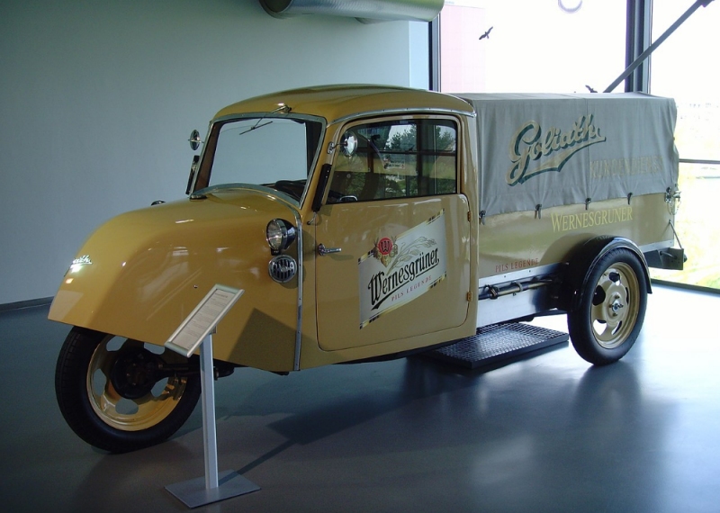 |
| Left: The Goliath F400 freight three-wheeler: 1933-35
The Goliath F400 was a freight version of the Pionier. It was powered by an air-cooled two-cylinder two-stroke engine giving 12 to 13.6 hp from a 396 cc displacement.
It has a Wikipedia page.
|
3 WHEELS IN LINE SLINGER MOTORCYCLE: 1901
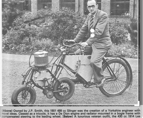 |
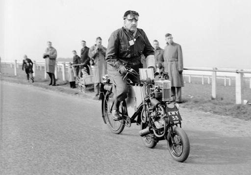
| Left: Three wheels in line Slinger motorcycle: 1901
This unique motorcycle is powered by a 499cc De Dion engine. The radiator is the round thing with the vertical pipes. The actual cylinder is on the other side of it. The first stage of the drive is a chain, and the second stage is another chain on the hidden side of the machine. It has a surface carburettor and coil ignition. It has no clutch and no gearbox, which must have compromised the performance. Apparently it could reach 35 mph in 1901.
The exact meaning of 'compensated steering' is opaque, but there is a link from the front fork of the bicycle to the front fork of the mini-motorbike assembly. Note that the mini-motorbike swivels freely with respect to the bicycle, and is directed by steering the front wheel.
The machine was built in 1901, by W. (Billy) Slinger, an electrical engineer from Settle, Yorkshire. It took six years to build; and no others were constructed. Just what Mr Slinger was aiming at is unclear. The man in this picture is J P Smith, who owned the machine in 1949.
There is more info here here.
|
 |
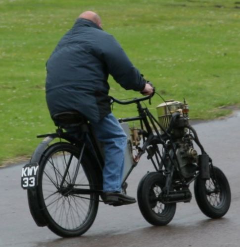
| Left: Three wheels in line Slinger motorcycle: 1901
J P Smith of Keighley sets off on his Slinger 1901 at the start of the 22nd Pioneer Run of the Sunbeam Motorcycle Club. According to my calculations this was in 1958 or 1962, but I am ready to be corrected.
|
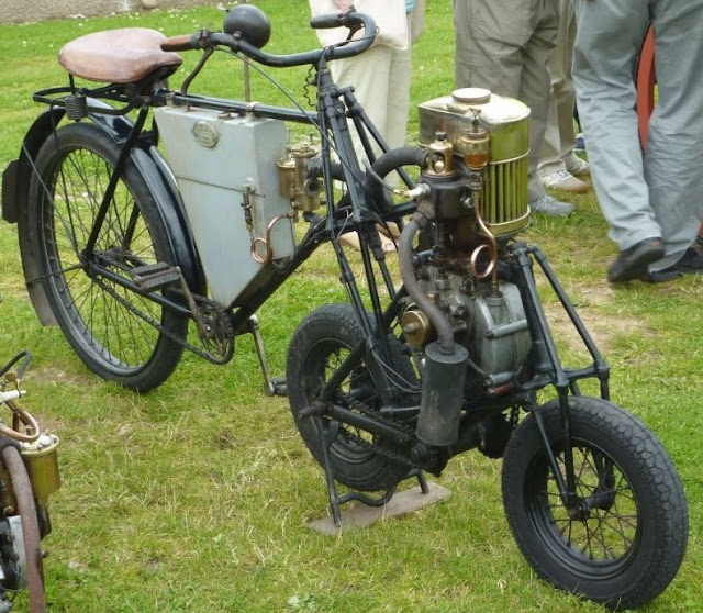 |
| Left: Three wheels in line Slinger motorcycle: 1901. Location & date unknown
Amazingly the machine still exists. You can even see a video of J P Smith riding it taken during the 1955 Banbury Run, on YouTube. It appears the whole mini-bike at the front swivels as a rigid unit, but it is hard to be sure. YouTube gives the date of construction as 1903.
The grey box contains the petrol tank in its upper section, as shown by the location of the petrol pipe. It is not known what was in the lower section; water for the cooling system, perhaps?
|
 |
| Left: Three wheels in line Slinger motorcycle: 1901
Pretty good proof that it still runs!
|
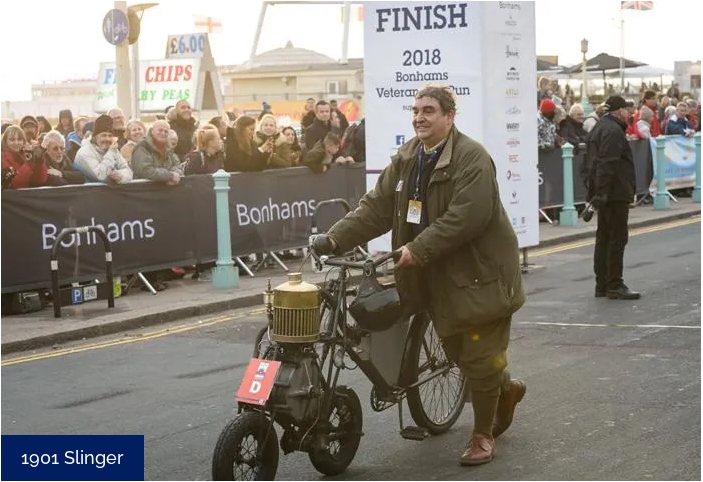 |
| Left: Three wheels in line Slinger motorcycle: 1901
This is the Slinger at the Finish Line of the London to Brighton Veteran Car Run in 2019. It is now owned by Mr Daniel Ward, who is presumably pictured here. Since he is unlikely to have pushed this awkward machine very far, I think we can assume it completed the Run under its own power.
It is not on the list of entrants for the 2022 Run.
|
3 WHEELS: THE JAMES SAMSON HANDYVAN
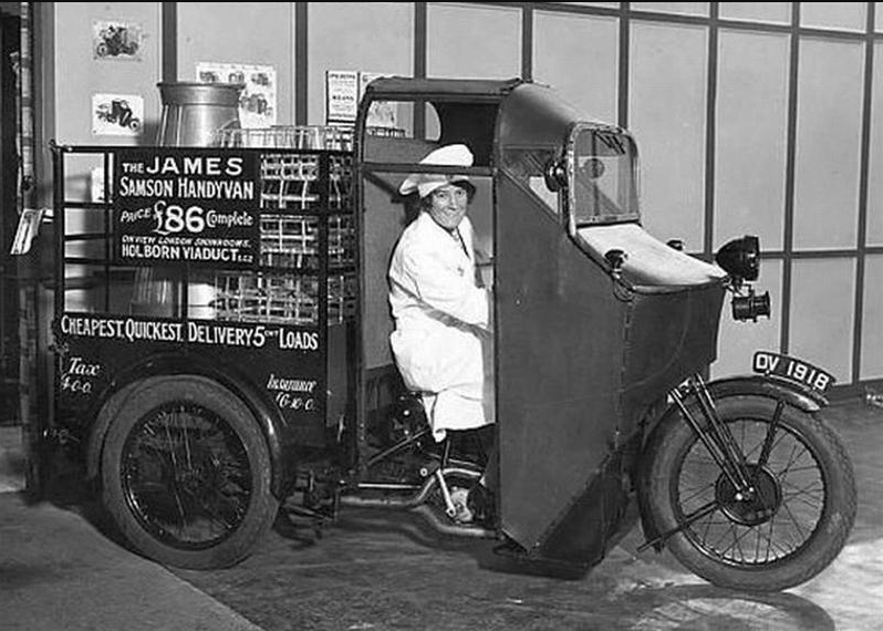 |
| Left: James Handyvan: 1929
The James Handyvan was introduced in Britain in 1929 by the James Cycle Company, and survived in production until 1939.
Early Handyvans were powered by an engine of only 247cc but offered a payload of 5 cwt. In 1933 the engine was upgraded to a more capable 1096cc V-Twin, and the payload was increased to 8cwt or 12cwt. Later models were called the “Samson Handyvan”.
The front of the body is of odd construction, and appears to give rather limited forward vision. The engine kick-start can be seen just below the driver.
There is more info here
There were several other van-bodied motor-tricycles, such as the Raleigh and the BSA.
|
3 WHEELS: THE GRAHAM THREE-WHEELER
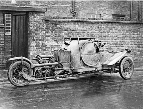 |
| Left: Graham three-wheeler: 1929
This is an odd three-wheeled car made by Mr A Graham of Kingston, Surrey in 1929. It was used in a 1929 British film called High Treason directed by Maurice Elvey. It was based on a play by Noel Pemberton Billing, who we have met before. The film was set in 1940 and the three-wheeler was given some 'futuristic' bodywork. It is safe to say 1940 did not turn out as planned for most people.
The engine was said to be a motorcycle type, and it looks as though it was a wide-angle air-cooled V-twin; note the fishtail exhaust. Drive was to he rear wheel.
Graham was said to be a racing driver, but no trace of him has been found on Google.
Thanks to Dr Lawrence E. Hawkins for drawing this vehicle to my attention.
|
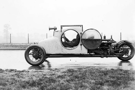 |
| Left: Graham three-wheeler: 1929
Here it is out in the wet. A maximum speed of 70 mph was claimed. It was said the body was made entirely of sheet iron.
Note the hefty klaxon on the front; you'll know it's coming.
There is more info here
Thanks to Dr Lawrence E. Hawkins for drawing this vehicle to my attention.
|
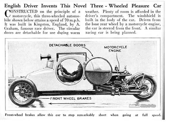 |
| Left: Graham three-wheeler: 1929
This article is from Popular Science or a similar magazine, date unknown.
It was clearly drawn from the photograph above.
|
 |
| Left: Graham three-wheeler: 1929
This is apparently Graham and wife setting out on their honeymoon. The number plate is good evidence that it the car was street-legal.
Note the hefty cabin-trunk on the roof.
Thanks to Dr Lawrence E. Hawkins for drawing this vehicle to my attention.
|
 |
| Left: Graham three-wheeler: 1929
A still from the film High Treason showing the Graham 3-wheeler with bodywork added.
Note the fairing around the klaxon. I think that's a nice touch.
The wedge-shape behind the man is probably an opening that is a nod towards cooling the engine. I don't see that working without some sort of fan arrangement.
|
3 WHEELS: HARLEY-DAVIDSON SERVI CAR
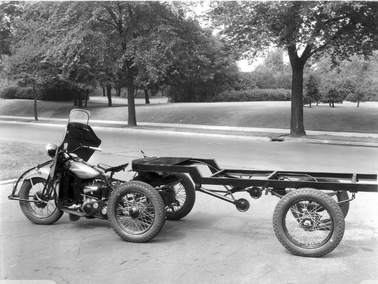 |
| Left: Harley-Davidson three-wheeler: 1937
According to one source, this is a 1937 Rick Servi Car, but others say it was made by Harley-Davidson. The rear carrier box has been removed and a trailer hitch installed.
There is some more info on Facebook, and more here.
I have resisted the temptation to call this a five-wheel vehicle.
|
3 WHEELS: BROUGH SUPERIOR MOTORCYCLE WITH DOUBLE REAR WHEELS
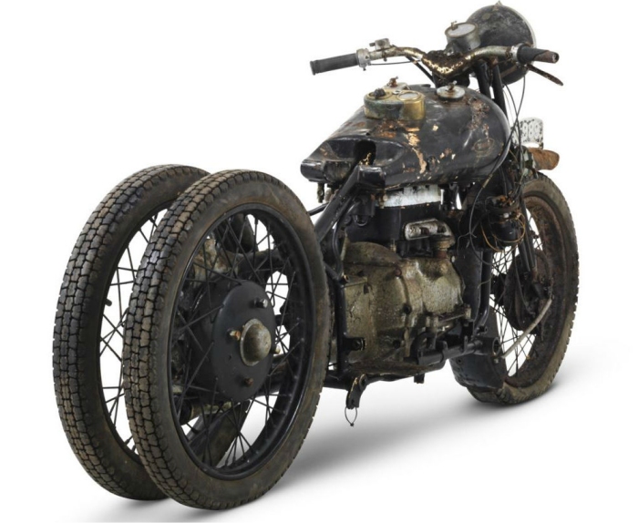 |
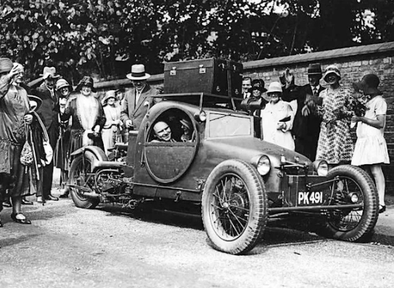
| Left: Brough Superior motorcycle with double rear wheels: 1932
The Brough Superior Austin Four was a limited-production motorcycle designed and manufactured by Brough Superior of Nottingham, Britain; it was built from 1932 to 1934. Only ten were built, of which nine survive. Unusually, it was powered by a proven Austin 4-cylinder sidevalve, water-cooled motor of 747cc. Brough increased the Austin engine displacement to 797 cc and replaced the cylinder head with a light alloy version which gave more horsepower, presumably by increasing the compression ratio. The rear wheels were shaft driven from a standard Austin 7 three-speed gearbox, (plus reverse) with a crown wheel and pinion mounted between the two rear wheels. You might think that twin rear wheels would make the handling tricky, but the Museum Staff have not so far found any evidence for this.
The twin rear wheels make it a three-wheeled vehicle, though legally it was still classed as a motorcycle because the rear wheel centres were less than 24 inches apart. The machine was primarily intended for sidecar work, which would presumably yield a four-wheel vehicle.
The Brough Superior Austin Four has a Wikipedia page.
|
3 WHEELS: MODIFIED M4 SHERMAN TANK: 1944
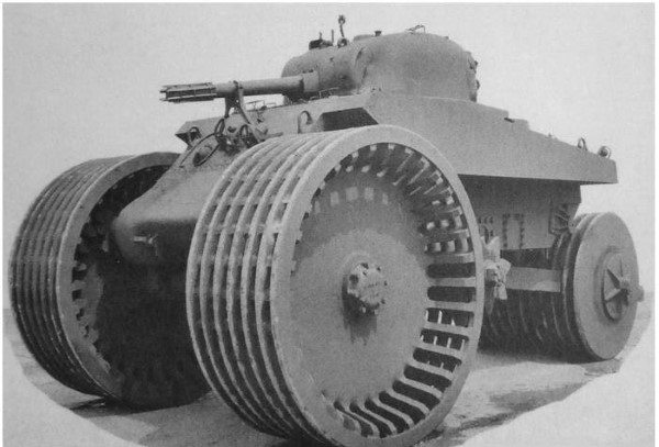 |
| Left: M4 Sherman tank modified for mine-clearing: 1944
This is an M4 T10 mine clearing prototype built by the USA in 1944, based on a M4 Sherman tank. The original intention was to install engines in the two front wheels, but initial testing was done without them. It weighed 52 tons, and the front wheels were 8 feet in diameter, while the rear roller was 6 feet in diameter. It's nickname was indeed 'tricycle'.
I'm prepared to call this a three-wheeler because the 'rear wheel' appears to be a single roller running the width of the vehicle. The big open-tread front wheels were designed to set off landmines, like the mine flail vehicles of WW2.
There are a good number of imaginary vehicle pictures that have been created by Photoshop, and you have to be careful. This looks like it could one of them, but research confirms it is genuine.
|
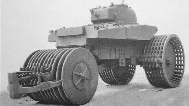 |
| Left: M4 Sherman tank modified for mine-clearing: 1944
The front wheels were driven by the tank sprocket-wheels engaging with internal teeth on the inside of the wheel; these can just be seen on the wheel at the extreme left. The star-shaped teeth on a shafts engaging with the metal tread were for clearing the wheels of debris, incuding explosive debris. There is another such shaft for the rear roller. I originally said they were for propulsion; many thanks to Bill Todd for pointing out this infelicity.
The prototype was reconfigured to use the tank's internal engine, and the underside was reinforced with 25mm steel plate. The M4A2 had 55 inches of ground clearance. The total width of the cleared path was 153 inches. (the front wheels had a width of 36.5 inches each) The tank could only reach 3 km/h when mine clearing, but on the road it could make 10 km/h. In June 1944 the T10 was tested, but it became clear that it was just too heavy to be practical.
The idea never got past this single prototype.
|
3 WHEELS: THE DAVIS DIVAN: 1947
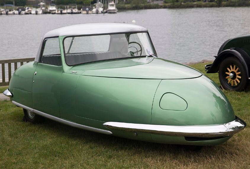 |
| Left: The Davis D-2 Divan: 1947
The Davis Divan was a convertible three-wheeler introduced by Glen Gordon "Gary" Davis, a used-car salesman from Indiana. It had two wheels at the back and one at the front. Most Divans were powered by a 2600 cc engine producing 63 HP.
A notable feature of the Divan was that it was wide enough to seat four passengers abreast on its single bench seat. Hence the name, which is the Arabic term for a couch.
Only 13 Divans (including two prototypes) were ever built, of which 12 apparently still exist. The car never made it into mass production; the company collapsed in 1949 and Davis was nailed for fraud.
The Davis Divan has a Wikipedia page.
|
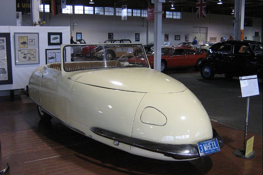 |
| Left: The Davis D-2 Divan: 1947
Another Davis Divan, with the top down. Here it is on display at the Lane Motor Museum in Nashville, Tennessee.
|
3 WHEELS: PEUGEOT TRIPORTEUR
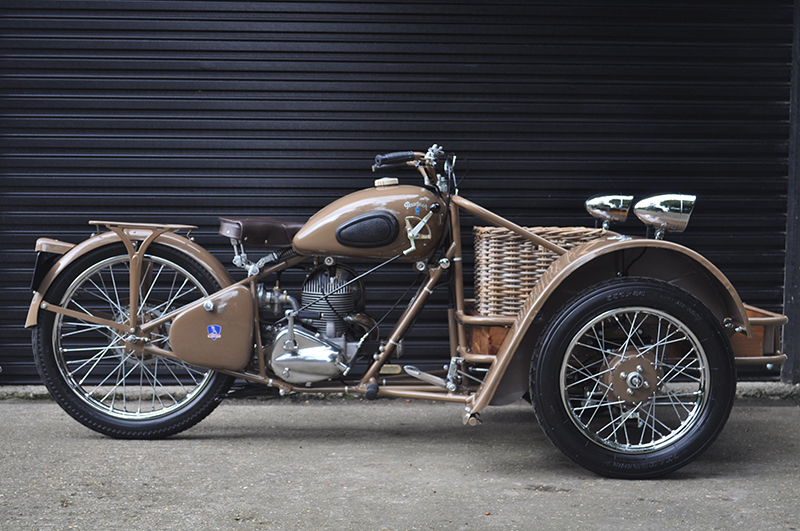 |
| Left: Peugeot Triporteur: 1953
The Peugeot Triporteur was essentially a three-wheeled single-cylinder motorbike for carrying small loads. This is an original example that has been faithfully restored; it dates from early 1953.
The earlier 53TM 100 cc model could carry 120 kg in the crate at the front; the later 55TN 125cc model could carry 150 kg. Maximum speed was 45 km/hr. Production was from 1939 to 1959.
|
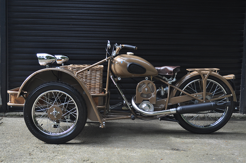 |
| Left: Peugeot Triporteur: 1953
The engines were 2-stroke with flywheel magneto ignition. Lubrication was by petroil mixture. There was a 3-speed gearbox by operated by a lever on the petrol tank. Primary and secondary transmissions was by chains.
|
 |
| Left: Peugeot Triporteur: 1953
This example appears to have a duct for air-cooling around the cylinder.
|
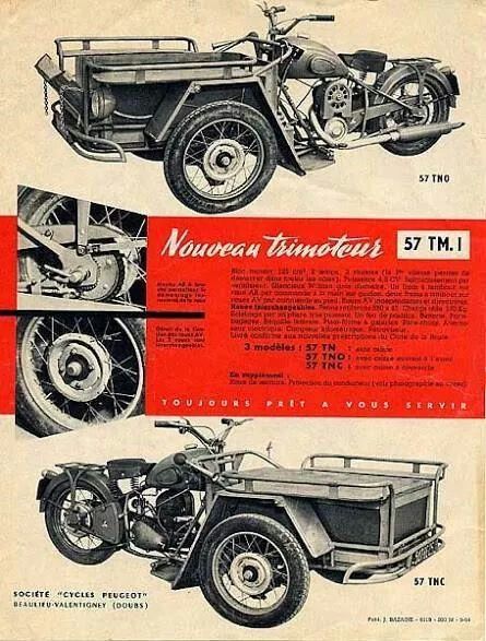 |
| Left: Peugeot Triporteur: 1939
Contemporary advert for the Peugeot Triporteur.
|
3 WHEELS: RELIANT ROBIN: 2018
Three-wheeled cars are not considered very unusual in Great Britain at least, though they are now becoming rare. Historically, three-wheeler production was encouraged by lower road tax than four-wheel cars, and because they could be legally driven with a motorcycle licence. (The latter legal situation changed recently)
The major 3-wheeler manufacturers in Great Britain were Reliant and Bond. Ultimately Reliant bought out Bond, and it was Reliant that produced the famous Bond Bug.
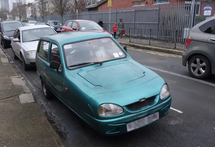 |
| Left: A Reliant Robin: 2018
The Reliant Robin was first produced in October 1973 to direct replace the Reliant Regal
The Reliant Robin had a water-cooled engine (originally only 750cc) under the hatch at the front, driving the back axle via a conventional propshaft and differential. The last Robin came off the production lines in 2002, the last batch of 65 having leather seats, alloy wheels, and walnut dashboards. Now that is class.
This Reliant lives a couple of steets away from me, and there is (or was) another living only half a mile away. I see one driving around occasionally, but have not so far been alert enough to spot which it is.
The crash-worthiness of a fibreglass-bodied car is not great. As was demonstrated when a friend of mine was killed in a Reliant Robin.
Author's photograph: Jan 2018
|
3 WHEELS: MORGAN
The Morgan company began selling three-wheelers with one wheel at the rear and a V-twin engine at the front in 1911, and continued until 1952. The company announced that production of a version using a Harley-Davidson V-twin would be restarted in 2012, but the production models actually used an S&S engine.
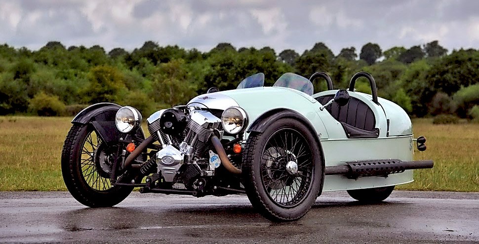 |
| Left: The Morgan three-wheeler: 2012
This is a three-wheeler of a rather different stamp. It is powered by a big V-twin engine at the front (yes, I suppose that is obvious) that drives the rear wheel.
There is a Wikipedia page on Morgan.
|
A perhaps non-obvious drawback of three-wheelers is that since you are making three tracks on the road, the chances of encountering a randomly-placed nail are increased by 50%.
3 WHEELS: LOMAX 223
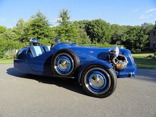 |
| Left: The Lomax three-wheeler: 1982
The Lomax three-wheeler is a British kit car in the same configuration as the Morgan, with two wheels at the front and one at the back. It has a fibreglass body mounted on a Citroën 2CV or Citroën Dyane floorpan. In later versions a steel tube chassis was introduced to replace the floorplan. The first Lomax 223's were powered by a Citroen 2CV 602cc engine, which is a horizontally-opposed air-cooled twin.
The Lomax is still in limited production at Cradley Motor Works, but production seems to be winding down.
The Lomax has a Wikipedia page.
|
3 WHEELS: THE PEEL P50
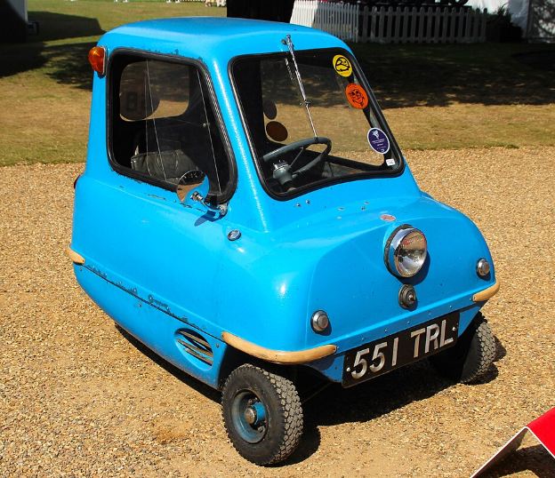 |
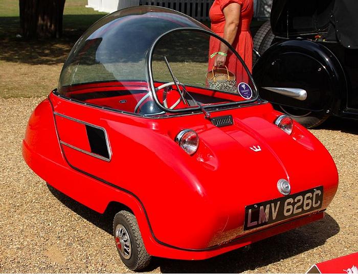
| Left: The Peel P50 three-wheeler: 1965
The Peel P50 was a microcar built by the Peel Engineering Company between 1962 to 1965. It was a minimalist one-seater powered by a 49.2 cc DKW single-cylinder engine, yielding a maximum speed of about 38 mph). It has a three-speed manual transmission with no reverse gear; it could be pulled about with a handle on the back of the car.
According to the 2010 Guinness World Records it was the smallest car ever put into production.
The Peel P50 has a Wikipedia page.
|
3 WHEELS: THE PEEL TRIDENT
 |
| Left: The Peel Trident three-wheeler: 1965
The Peel Trident three-wheeler was produced by the Peel Engineering Company, which was based on the Isle of Man, in 1965 and 1966. It was their second microcar, seating two people (just) coming after the Peel P50, (see just above) which only seated one. (The P50 holds the record as the smallest car ever to go into production)
It used a 49 cc DKW engine which developed 4.2 HP, and gave a top speed of 28 mph. Note the complete absence of any rollover protection, and it looks like you could roll it easily.
The Peel Trident has a Wikipedia page.
|
4 WHEELS
4 WHEELS: THE SUNBEAM-MABLEY: 1901
As noted at the start, there is pretty near universal agreement that the best number of wheels for a car is four. There's not much point in looking at ordinary cars here, but you can have four wheels and be unconventional about where you put them. A classic example is the Sunbeam-Mabley:
Quadracycles (essentially four-wheel bicycles) have a separate gallery here.
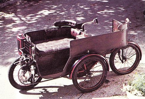 |
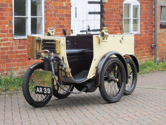
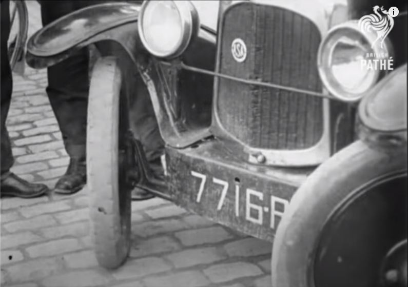
| Left: The Sunbeam-Mabley: 1901
This car was the first produced by the famous Sunbeam company. They bought in a design from a certain Maxwell Mabley-Smith, whose day job was designing ornamental ironwork. There is variation in the spelling, with Mabberley and Maberley both about on the Web. Mabley is the correct version.
The Sunbeam had one wheel at the front, one at each side, and one at the rear; this is often described as a diamond configuration, but in fact the front and back wheels were not in line. The layout was similiar to that of Starley's Coventry Rotary quadracycle. The car was powered by a single-cylinder 2.75 HP De Dion engine mounted next to the front wheel, but it did not drive this wheel at all. A belt from the engine ran backwards to a 2-speed gearbox and differential; chain drives ran from this to the two unsprung side wheels.
The seating was as unorthodox as the wheel placement. Two people sat close together on the front seat, facing the side of the road; the driver sat behind them, steering with a tiller and facing the opposite side of the road. This all sounds very unnatural; the natural tendency would be to twist round to look in the direction in which you are going. This is especially a good idea if you are the driver. Note that extra seat backs have been added at the corners of this version to make the twisting a bit less uncomfortable.
|
A small-diameter exhaust pipe goes round in an elegant semi-circle, then heads toward the rear. In the previous update I said 'Note the red-lined petrol tank mounted on the far side of the car' but it now appears it is a radiator header tank. Looking at the fins on the cylinder I assumed that the engine was air-cooled, but closer investigation shows that the cylinder head only is water-cooled and there is a four-row gilled-tube radiator mounted just above the engine. The petrol tank was somehow fitted in between the driver and the passsengers; for the time being the exact location remains enigmatic, but it must be reasonably high up for gravity feed to the carburettor.
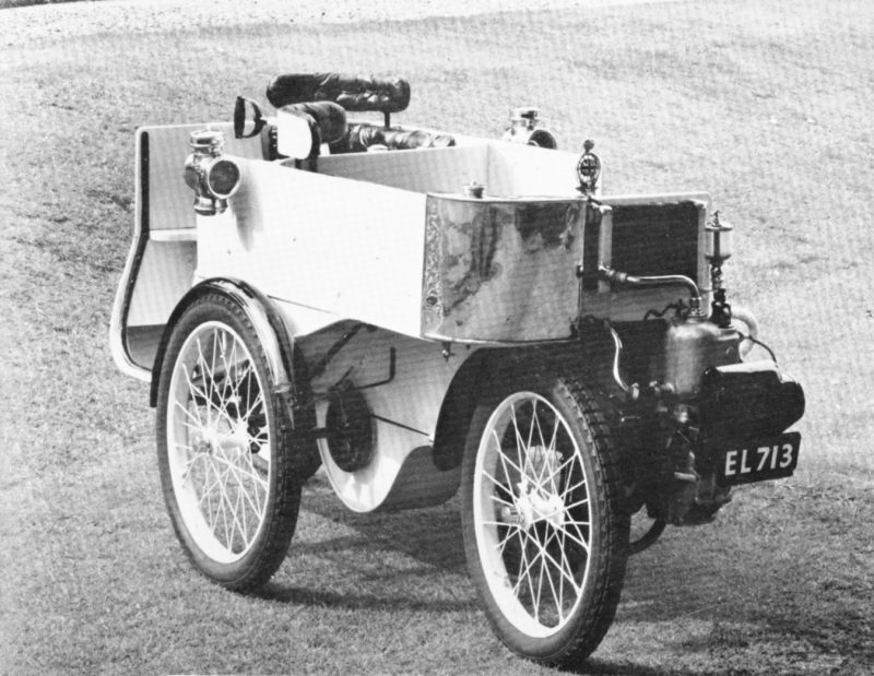 |
| Left: The Sunbeam-Mabley: 1901
This is another Sunbeam-Mabley; the engine here appears to be wholly water-cooled. This machine was sold by auction at Sotheby's on 23rd October 1969.
The auctioneer's blurb states that the engine is partly air-cooled and partly water-cooled, but this does not square with the appearance of the engine, which looks to be wholly water-jacketed.
The blurb states that the engine power was 2.75 HP, from a 74mm bore and 76mm stroke; the capacity was 327cc and the inlet valve was automatic. It also states that ignition was by trembler coil, but that looks like a magneto on the front to me. Its price when new was stated as £130.
The Museum staff have so far not been able to find out what it sold for in 1969.
|
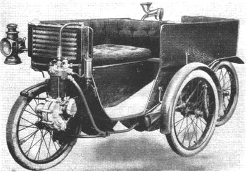 |
| Left: The Sunbeam-Mabley: 1901
This is a contemporary picture of the Sunbeam-Mabley. No extra seat backs here.
The engine here seems to have a water-cooled head and a finned cylinder barrel for air cooling. No radiator header tank is visible, and the radiator has six rows instead of four. No magneto is visible; I suspect the writer of the auctioneer's blurb mentioned above was working from this picture.
Remarkably the Sunbeam-Mabley had some success; several hundred were sold in 1901 and 1902 at £130 each. It was still in the Sunbeam catalogue in early 1904, offering a single cylinder 327 cc engine 74 x 76 mm to run at 1,800 rpm. Weight 4½ cwt. (which is very light) The price then was £120.
|
 |
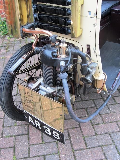
| Left: Sunbeam-Mabley AR39: 1901
This Sunbeam-Mabley was sold at auction for £65,000 in November 2011, which presents a good advance on the initial purchase price of £130.
The cylindrical silencer can be seen just ahead of the centre wheel.
AR39 has successfully taken part in the London-Brighton veteran car run.
|
 |
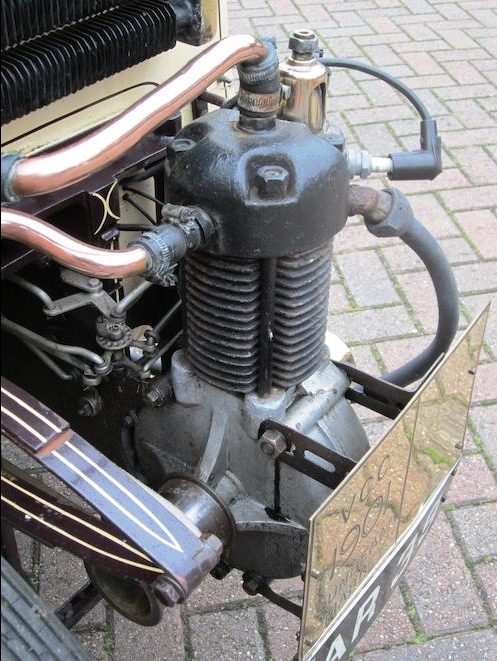
| Left: Sunbeam-Mabley AR39: 1901
It was this photograph that made it clear that the engine was partly water-cooled and partly air-cooled. It also shows that the tank at the front is a water header tank and not the petrol tank.
On the top of the cylinder head, in a copper housing is an automatic inlet valve; it opened against a light spring on the induction stroke. Simple but not conducive to good engine breathing. A black right-angle induction manifold connects it to the carburettor; immediately to the right is the polished copper float-chamber.
|
 |
| Left: Sunbeam-Mabley AR39: 1901
Here the wide pulley on the engine crankshaft can be seen; the belt is not fitted.
Just to the left of the cylinder barrel can be seen two control rods; presumably they work the throttle and choke on the carburettor.
|
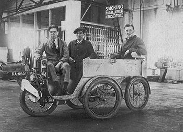 |
| Left: A Sunbeam-Mabley at the Sunbeam works
The engine arrangements look rather different here, but the photograph is not clear enough to make out any details.
The date is unknown but must have been in the period 1901 - 1904.
|
4 WHEELS: THE ALAMAGNY DOUBLE-ENDED CAR: 1947
 |
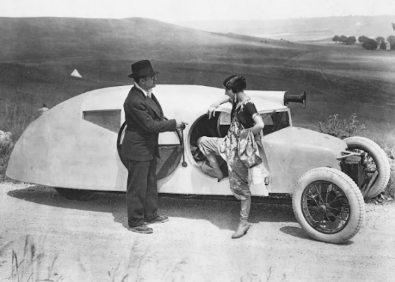
| Left: The Alamagny Double-ended Car: 1947
I though it highly unlikely that anyone else had tried making a car with a diamond layout of the wheels.
I was wrong. Firstly I found the Pininfarina-X project of 1960, and now this.
This is the Alamagny Double-ended Car, which had the two middle wheels powered, and both front and rear single wheels steered, which must have produced some interesting handling. Front and rear ends looked almost identical, though presumably the lights were different. The car was however always driven from the 'front' end. There were two headlights mounted one above the other behind the grille.
Two passengers faced forward and two backwards, looking out of the rear window. That does not sound like it would be a popular seating arrangement. The aluminium bodywork has two identical hinged clam-shell canopies that lift to give access to the seats.
There is a Wikipedia page.
|
 |
| Left: The Alamagny Double-ended Car: 1947
The car was powered by a central transversely mounted four-cylinder water-cooled 569 cc engine adapted
from the Simca 5.
The Alamagny was exhibited on several occasions in 1947 and 1948, but no-one was interested in producing it.
You can see a video about the car on YouTube but the commentary is distinctly irritating.
Many thanks to the correspondent known to me as Bacony Cakes for drawing this machine to my attention.
|
4 WHEELS: THE PRVENAC CAR: 1959
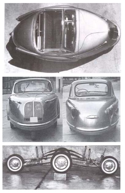 |
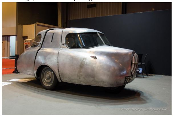
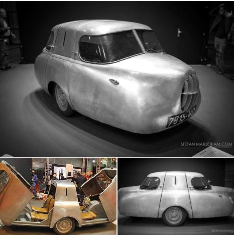
| Left: The Prvenac Car: 1959
The Prvenac car was another design with a lozenge distribution of the wheels, though this one was not double-ended. It was put forward by Dr. Miroslav Nestorovic in 1959. The prototype was constructed in the David Pajic factory (which manufactured lifts rather than cars) in Belgrade, in what was then Yugoslavia. The car had a single, three-person bench seat and a removable roof. It never saw producton and was dismantled in the 1970s.
Both front and rear wheels steered, while the centre axle was driven by an air-cooled two-stroke Tomos-Puch 250cc 14 HP engine.
Prvenac is a Serbo-Croat word that can mean: debut, firstborn son, or the run of first rakija from a brandy still.
There is more info here.
|
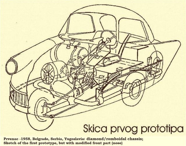 |
| Left: The mechanical arrangement of the Prvenac Car: 1959
The single-cylinder engine is at the front, just to the right and above the front wheel. The steering wheel is connected to the front wheel, and that is connected to the rear wheel by two rods with a lever (just to the left of the nearest side wheel) that reverses the steering action for the rear wheel.
|
4 WHEELS: THE KESLING YARE ELECTRIC CAR: 1978
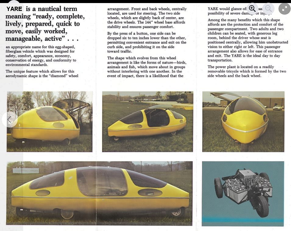 |
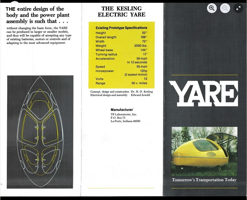
| Left: The Kesling Yare electric car: 1978
The Kesling Yare electric car was another design with a diamond wheel pattern. It had a 72 Volt battery and could reach 55mph. (allegedly) The picture at bottom right appears to show six conventional truck-size lead-acid batteries; 6 x 12V = 72V.
The range was claimed as "50+ miles".
Apparently the prototype is in a museum in LaPorte, Indiana. It was the only one made.
Source: 1978 Kesling Electric Yare Brochure. USA. Fold-out.
|
 |
| Left: The Kesling Yare electric car: 1978
Reaching 55 mph in 12 seconds sounds rather leisurely.
Source: 1978 Kesling Electric Yare Brochure. USA. Fold-out.
|
4 WHEELS: THE VICKERS-WOLSELEY STAFF CAR: 1926
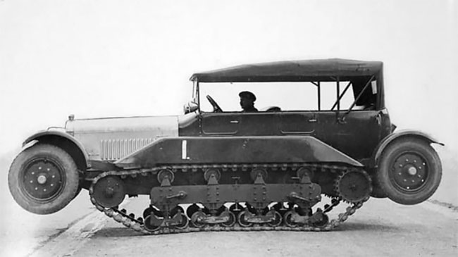 |
| Left: Vickers-Wolseley Staff Car: 1926
This is another attempt to combine the advantages of wheels and tracks. It was a conversion- a rather radical conversion- of a Wolseley touring car. Here the wheels are raised so the vehicle travels on its tracks.
Source: Miltary Transport of WW1 by C Ellis and D Bishop, Blandford Press 1970.
|
 |
| Left: Vickers-Wolseley Staff Car: 1926
Here the wheels are lowered for road use. The track system is rigidly attached to the car body. The design was not a success, proving complicated and expensive; there were doubts about its stability. The idea was tried again in 1927 on what might be regarded as an armoured car, but that also was not proceeded with.
Source: Miltary Transport of WW1 by C Ellis and D Bishop, Blandford Press 1970.
|
4 WHEELS: SIDEWAYS PARKING IN 1927
 |
| Left: Sideways parking: 1927
You can see a video here of a car with the front wheels set at right angles to the usual direction of motion. When the front of the car has been swung out sideways, the front wheels swivel outwards to the normal configuration.
The car is believed to be a Citroën B12 Torpedo, and the location Paris. However there is another video that gives the location as Arras in France.
This sort of thing has never caught on, presumably because the extra weight and complication was too great compared with the limited number of times it would have been useful.
Source: Pathe newsreel issued 2nd May 1927. More info here.
|
 |
| Left: Sideways parking: 1927
There is no sign of any extra mechanism around the stub axles; this suggests the wheel-swivelling was done by altering the effective length of the track-rod. (tie-rod) There is also no sign of front-wheel drive, which suggests that the car was swivelled by causing the rear wheels to turn in opposite directions, requiring an extra gearbox.
A related concept is the zero-turn lawnmower, which can turn around on the spot. Some of these have five wheels...
|
4 WHEELS: SWEDISH STRIDSVAGN FM/30 L-30 CONVERTIBLE TANK/ARMOURED-CAR: 1931
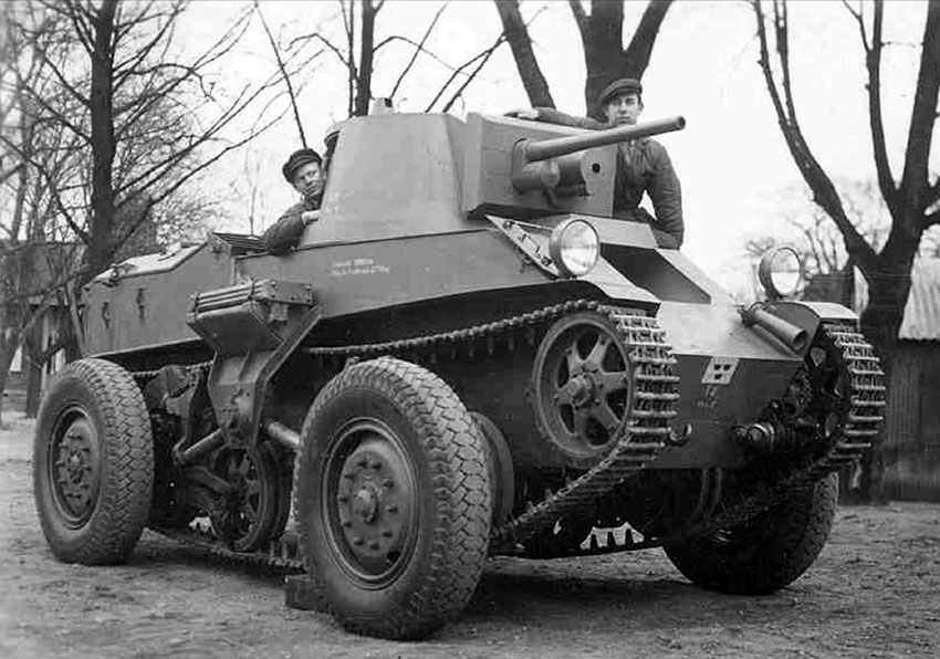 |
| Left: Stridsvagn FM/30 L-30 convertible tank/armored-car: 1931
Shown here with the wheels down.
This remarkable vehicle certainly has four wheels, but it also has a pair of caterpillar tracks. It also has a complicated history.
The vehicle was designed and constructed by the German engineer Joseph Vollmer, who was at the time co-owner of the German Automobile Construction Company (DAC). The manufacture of tanks was forbidden in the German Reich due to the Treaty of Versailles. To evade this, the the GHH (Gute Hoffnungs-Hütte) steelworks group, based in Oberhausen had acquired the Landsverk company in Landskrona, Sweden. Vehicles and engines were designed and then sold as complete factory drawings against future royalty payments.
The FM30 had a 150 HP engine, weighed 11.5 tons and could exceed 45 mph (75 km/h) on the road using its wheels, and 20 mph (35 km/h) across country using its tracks. To convert to tracked operation, both sets of wheels were raised until the top of them were level with the tank deck. The transition to wheeled mode took about 30 seconds and could be done on the move. The armour was proof only against small-arms fire.
|
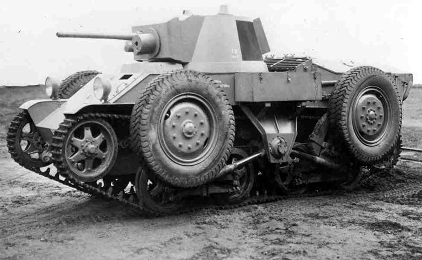 |
| Left: Stridsvagn FM/30 L-30 convertible tank/armored-car: 1931
Shown here with the wheels up.
The armament was a Bofors 37mm gun (122 rounds carried) and 6.5mm machine-gun. (4000 rounds carried) For some reason the machine-gun was mounted in a short fat cylinder. Note the hatch on each side of the turret.
Perhaps predictably, the dual-drive system was complex to manufacture and too fragile for military use. Tests took place in 1935-36, but the single example was relegated to training until 1940. It has been preserved and can be seen in the Swedish Arsenalen Museum in Strängnäs. Their website is here.
There is a very short Wikipedia page for the FM/30.
|
4/6 WHEELS: SWEDISH FM-29 ARMOURED-CAR: 1932
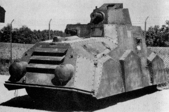 |
| Left: The Swedish FM29 armoured car: 1932
This Swedish armoured car design resembled the German one just below in that it had four wheels in normal use, plus two spare wheels which were mounted so they contacted the ground in rough country and prevent the vehicle getting stuck; it's another case of 'is this a 4 or 6-wheeled vehicle'?. The four main wheels were driven and steered at each end.
The wheels in the picture are hidden behind the pentagonal armour plates. The rear of the vehicle is towards the camera, and tyres contacting the road can be seen at each end- but the middle pentagonal plate has no tyre visible under it. The phrase 'rear of the vehicle' is a bit of a doubtful one in this case: the FM29 had a driver and controls at each end, allowing for some spectacularly rapid retreats.
You may be worried that this armoured car appears to be equipped with a pair of torpedo tubes. In fact the two circular hatches cover the headlights; the headlights at the 'rear of the vehicle'.
Only one example was ever completed; the design proved too big and heavy, and too expensive.
Many thanks to Tulle Rönnmyr for bringing this vehicle to my attention.
|
 |
| Left: Swedish FM29 armoured car chassis: 1932
The FM29 demonstrates its ability to deal with a hump, though the spare wheels aren't actually doing anything at the moment. It also gives a very good view of the front and back driving positions.
The disc wheels formed part of the protection of the crew. The engine can be seen at the rear of the vehicle. (To the right)
Many thanks to Tulle Rönnmyr for bringing this vehicle to my attention.
|
4 WHEELS: THE ADMK MULUS: 1935
 |
| Left: The ADMK Mulus with all four wheels up: 1935
The Austrian ADMK Mulus was a light machine-gun carrier vehicle that, like the Stridsvagn FM/30 above, could proceed either on its tracks or on its four wheels. It does not qualify as a tankette because it had no armour at all.
The front wheels could be swung upward on their gear-driven suspension arms. They could then be removed and put into brackets at the rear of the vehicle. The rear wheels could also be removed, but this was a more complicated process that required driving the tracks up onto blocks.
It has been written that a unique feature was that the front arms acted as a framework for the driver's seat, but so far no information on how this worked has been found.
It was first produced in prototype quantities in 1935, and continued in production until 1938. Total production was 334 units; 302 of them in 1936. The Mulus was taken over by the German army after the 1938 Anschluss, but does not seem to have had much use, probably because it was underpowered, only having a 20 HP engine to move a 1.5 ton vehicle. Some were used in training for Operation Sealion.
The Mulus has a short Wikipedia page. In German, but Google Translate does a good job.
|
 |
| Left: The ADMK Mulus with the front wheels only down: 1935
- Weight: 1.56 tons
- Engine: Daimler air-cooled 4 cylinder 20 HP
- Speed: On tracks 10 mph, on wheels 27 mph
|
 |
| Left: The ADMK Mulus with all four wheels down: 1935
Here a two-wheeled trailer is towed.
|
4 WHEELS: THE AUSTRIAN RR7: 1936
 |
| Left: The Austrian RR7: 1936
The RR7 was another wheeled/tracked vehicle from Austria. It was developed in 1936 by the Swiss Saurer Company to serve as an artillery tractor. The changeover from wheels to tracks could be done while the vehicle was moving at a slow speed.
After testing, an order was an order was placed in 1937, but only 12 vehicles were built before the 1938 Anschluss. After this manufacture continued, and a total of 140 units were built; there might have been more, but the RR7 had poor handling and was difficult to steer.
The new German name for the RR7 was Sd Kfz 254. It had a 4-cylinder 70 HP diesel engine.
There is a short Wikipedia page on the Sd Kfz 254.
|
4/6 WHEELS: MIDDLE-WEIGHT AND HEAVY EINHEITS-PKW 1936
 |
| Left: Middle-weight Einheits-PKW with central wheels: 1936
Between 1936 and 1943 the Wehrmacht was supplied with Einheits-PKW (German for 'standard passenger cars') in the three versions; light, medium and heavy. These vehicles were supposed to provide cross-country mobility. They proved too complicated and expensive, their place being taken by the Volkswagen Kubelwagon, which proved capable of dealing with rough terrain despite only having two-wheel drive.
Shown here is the middle-weight version. On each side a spare wheel was mounted on a bearing, so it could rotate freely if it contacted the ground and so prevented the chassis grounding. While this feature seems rather ingenious, it must have failed to earn its keep as it was removed in 1940 to simplify the bodywork and make more room inside.
So- is that four wheels or six?
Many thanks to Bernd F and Pavel Panenka for drawing this machine to my attention.
|
 |
| Left: Heavy-weight Einheits-PKW with central wheels: 1936
This is very much the same as the middle-weight version, though the spare wheels are recessed further into the bodywork.
So- is that four wheels or six? Nobody's counting the two wheels on the gun being towed.
Many thanks to Bernd F and Pavel Panenka for drawing this machine to my attention.
|
3/4 WHEELS: THE HAYWOOD LHW SPECIAL: 1938
 |
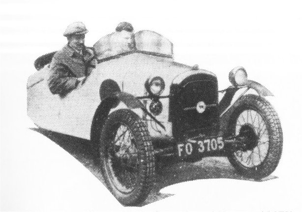
| Left: The Haywood LHW Special: 1938
The Haywood special was designed to exploit a feature of the rules in the International Six Days Trial held in Wales in 1938. The trials were intended for motorcycles and motorcycle-sidecar combinations, the latter having three wheels. According to the rules two wheels counted as one providing they were less than a foot (30 cm) apart. The special was based on an Austin Seven, and was built by three men called Lloyd, Hughes & Williams, and hence the LHW.
No information has so far been found as to how successful this scheme was, or what their fellow-competitors thought about it, but the Museum staff are on the case.
The car has been preserved and is currently owned by Iain Richardson.
|
 |
| Left: The Haywood LHW Special: 1938
The Austin Seven axle was cut down until only the differential remained.
|
 |
| Left: The Haywood LHW Special: 1938
A contemporary picture of the Haywood LHW Special.
|
4 WHEELS: HOME GUARD AMBULANCE: 1941
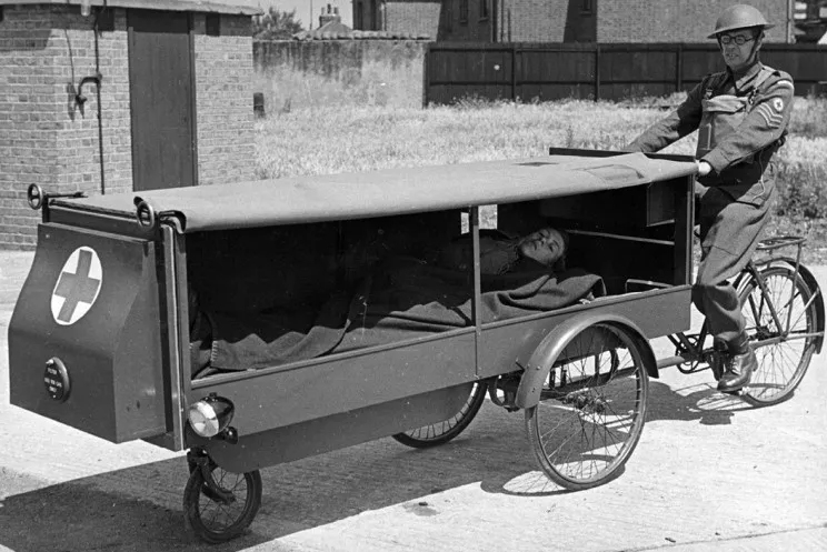 |
| Left: Home Guard diamond configuration ambulance: 10 August 1941
The Home Guard was a local defence organisation formed in Great Britain at the start of the Second World War. This one-person ambulance was intended for the transport of victims of war gases. (a threat which never materialised) It looks like a delivery tricycle with a much extended load carrier, supported by an extra wheel at the front.
It is not entirely clear how the steering worked. It looks as though the front section swivelled with respect to the rear of the tricycle, and moving it to change direction would need a lot of muscular exertion; the front wheel appears to be simply a castor. The wheels make up a diamond pattern like that of the Sunbeam-Mabley at the start of this section.
There is an odd-shaped box on the front, of unknown function.
Note curtains that can be let down on each side to keep out gas. Also, with gas in mind the rider is wearing his box respirator on his chest.
This picture is about on the Net, with claims it was the first ever ambulance; this is of course nonsense.
|
4 WHEELS: PININFARINA-X PROJECT: 1960
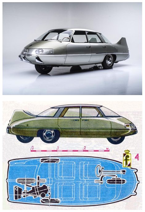 |
| Left: Pininfarina-X project: 1960
The Pininfarina-X project showcased its low-drag body design, with a drag coefficient of only 0.23, far superior to the ordinary cars of the time. Batista Pininfarina worked with aerodynamics expert Professor Alberto Morelli. To achieve such low drag the front of the car had to be narrow, leading to this unorthodox layout with one wheel in front, two at the side, and one at the rear. The front wheel did the steering and the single rear wheel all the driving, which must have made transmitting power to the road more difficult, but means you don't need a differential.
A 1089cc Fiat engine was installed at an angle in the rear of the car. This odd arrangement was made necessary by the rear three wheels being close together. This must have made for an assymetrical weight distribution and one wonders if that affected the handlng.
The project was a successful technology demonstrator up to a point, but a single front wheel was never going to be acceptable in mainstream motoring. The car was eventually bought by a collector and still exists.
You can find more information here.
|
4 WHEELS: SQUARE-WHEELED PICKUP
You're not going to get a car with four conventionally-placed wheels on this page, unless there's something very funny about the wheels. I think this car qualifies; it has four square wheels.
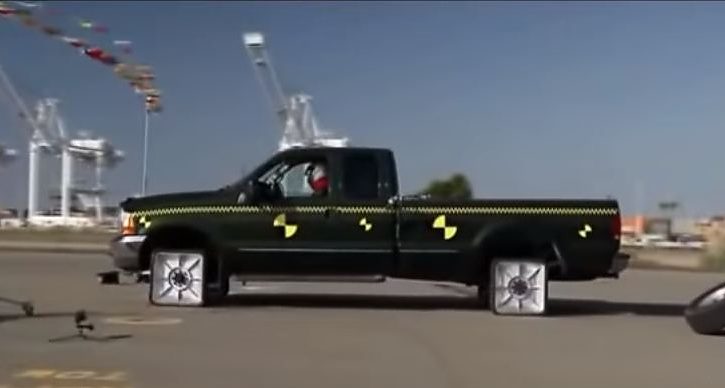 |
| Left: Square wheels on a four-wheel pickup
This is from a Mythbusters episode. Interestingly the jolting gets less as speed increases because the wheels are bouncing from one corner to the opposite one, the intermediate corner not touching the ground.
There is a YouTube video, posted in 2016.
It is slightly disturbing that this is far from a unique occurrence of square wheels. Typing 'square wheels' into YouTube produces scooters, bicycles, tricycles, tractors, motorbikes and skateboards, all with square wheels.
Presumably the ultimate Perverse Wheel would be an equilateral triangle.
|
5 WHEELS
5 WHEELS: THE PENTACYCLE
This is not strictly a car or motor vehicle, but when you are looking for 5-wheeled vehicles you can't afford to be too fussy.
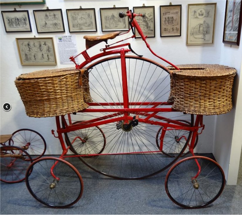 |
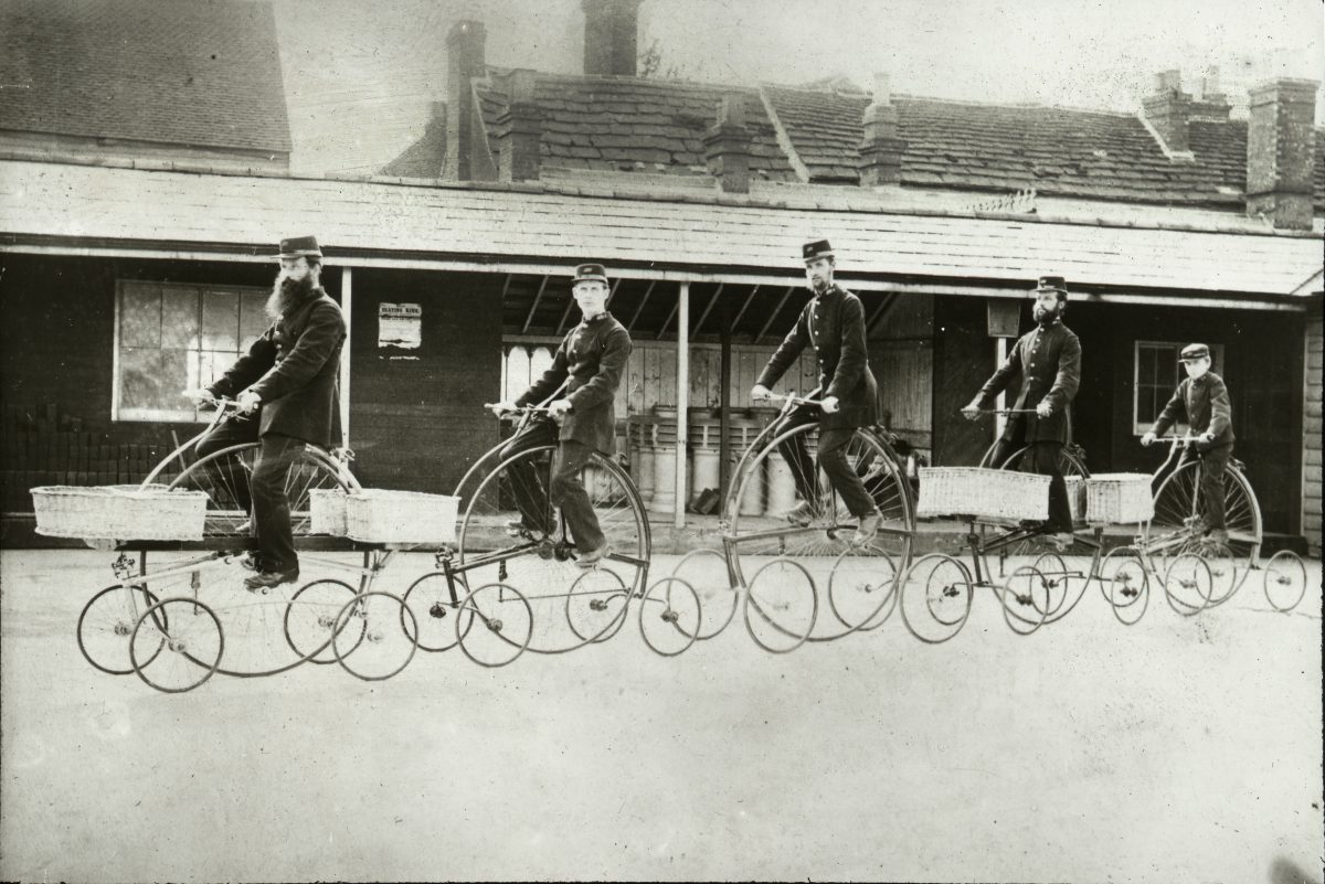
| Left: Burstow's Pentacycle: 1882
The Pentacycle was designed for delivering the post; it was patented by architect Edward Burstow (1821-91) in 1882. He is otherwise unknown to the Internet. It underwent trials with postmen in Horsham, England, and they apparently liked it, but apparently other areas were less enthusiatic and it was not adopted. Edward Burstow is buried in Denne Road Cemetery, Horsham. He was also responsible for designing the Corn Exchange, West Street, Horsham.
The thinking behind the design is obscure. The use of a large driving wheel avoided using gears or a chain to get up a decent speed, as in a penny-farthing, but at that date gearing was starting to be adopted. The use of what are essentially four stabiliser wheels to protect the health of the postman (going head-first over the front of a penny-farthing could easily be fatal) is laudable, but since there is no suspension, it would seem that it would be impossible to keep all five wheels on the ground, especially given the state of the roads at that time. If the centre wheel failed to grip the road you would go nowhere.
The machine steers on both the front and rear little wheels; otherwise it would probably have never got round corners at all. Note the lever to the right and below the pedals that changes the direction of the steering action so that the small-wheel axles steer in opposite directions.
The Pentacycle was often described as the 'hen and chickens' machine because it allegedly resembled a hen surrounded by four chicks.
The Pentacycle has a Wikipedia page.
|
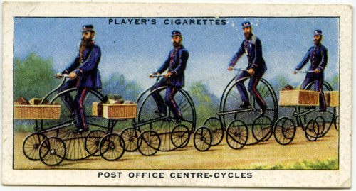 |
| Left: Burstow's Pentacycle: 1882
This cigarette card suggests that the official name for the machine was 'centre cycle', and other sources confirm this.
|
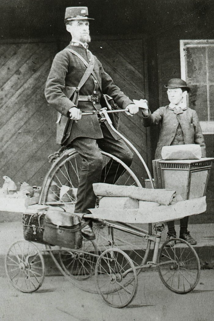 |
| Left: Burstow's Pentacycle: 1882
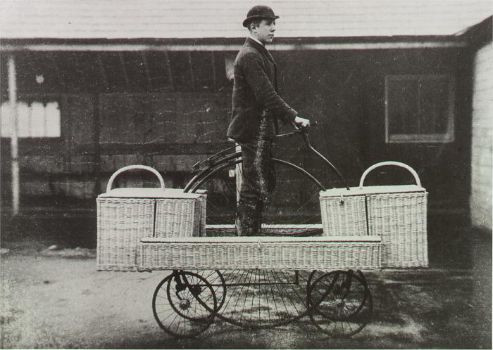
This is one of the very few contemporary photograph of a centre cycle in use. The machine appears to be fitted with shelves rather than baskets, and there are two pouches strapped to the frame on the left.
According to the Postal Museum: "Postmen complained that the cycle wore out their trousers in the crotch, leaving them with holes in their uniform. Since they had to pay for their own uniforms, they refused to use the cycle and it was consigned to the scrap heap."
Sounds like the design of the saddle could have been improved. Why wasn't it?
|
 |
| Left: The Horsham fleet of centre-cycles: 1882
There appear to be at least two, and possibly three sizes of centre-wheel shown here.
This photograph seems to have been taken at the same location as the one just above; presumably it was the yard of the Horsham Post office.
|
 |
| Left: Burstow's Pentacycle: 1882
This is pretty clearly the same location, but the centre-cycle here has a different set of baskets from the one seen in the picture just above.
|
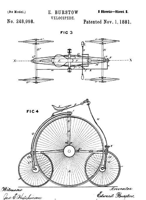 |
| Left: The USA patent for the centre-cycle: 1881
Edward Burstow clearly thought it was worthwhile to get a US patent for his machine.
The upper diagram shows the levers connecting the steering wheels at back and front. There is however no sign of the lever which caused the small-wheel axles to steer in opposite directions.
|
5 WHEELS: THE PHELPS TRACTOR
Finding a car with five wheels was always going to be a challenge. However the Museum staff are not easily defeated...
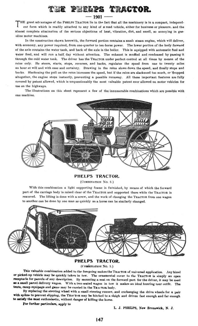 |
| Left: Advert for the The Phelps Tractor: 1901
The Phelps Tractor was an ingenious idea that failed to become popular. The steam-powered propelling section was a three-wheeled unit controlled by steering rods from behind. Presumably this was to reassure potential purchasers who were more used to driving horses and wanted no truck with new-fangled notions like steering wheels.
The propelling unit could be coupled to a carriage (Combination 2) or a parcel wagon (Combination 3, with extra storage over the engine compartment) or any other suitable trailer unit. This included sledges.
The advert at left describes how to steer, start, stop, and reverse, with the useful feature that the engine stops if the rods or reins are dropped or otherwise released entirely.
It think the top version has a reasonable claim to be a 5-wheeled car; you couldn't drive the tractor unit around by itself. The claim of the lower version to be a 7-wheeled car is more dubious, as the trailer is essentially a separate vehicle.
There seems to be much doubt as to whether this machine was actually built- there appear to be no photographs. I have grave doubts as to the practicality of fitting a 10-HP steam engine, complete with fuel and water tanks, in an enclosure the size of that shown in the top picture. Significantly, no chimney is shown to carry away the boiler exhaust gases, and there is no sign of an air-cooled condenser, which would be a sizable item.
|
5 WHEELS: A TRUE FIVE-WHEELED CAR
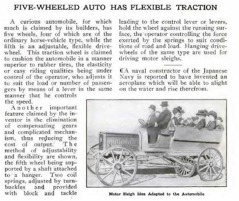 |
| Left: Car with central fifth wheel: 1911
While there could be argument about some of the vehicles in this section, this is I think beyond dispute a true five-wheeled car. Details are sadly lacking but it appears that the amount of load taken by the fifth wheel could be adjusted as the vehicle moved along.
The inventor claims "the elimination of compensating gears and complicated mechanism". I suspect 'compensating gears' means a differential on the driving axle; close examination of the photograph shows there is a chain drive to the fifth wheel, but no chains going to the rear axle. It therefore appears that the fifth wheel was the sole means of propulsion, which might be expected to cause problems with traction. It is not easy to see what good having a variable load on this wheel would do; using a block-and-tackle in the mechanism suggests a certain lack of mechanical sophistication. In all, it does not appear to me to be a good idea.
Source: Popular Mechanics March 1911. Many thanks to Kerry Stiff for drawing this machine to my attention.
|
5 WHEELS: THE DETROIT TRACTOR
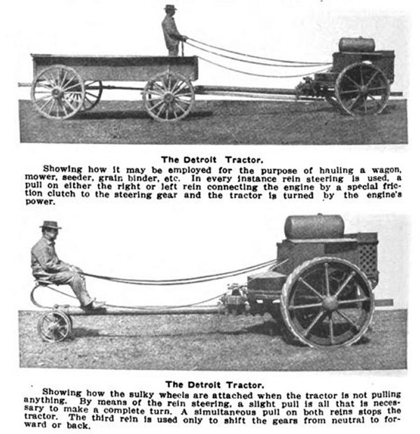 |
| Left: Advert for the Detroit Tractor: 1913
The Phelps Tractor was not unique in its rein-control. The Detroit Tractor (which judging by these photographs really was built) had a more practical internal-combustion engine. It is not clear why the towing pole was so long- it may have been something to do with using unmodified horse-drawn ploughs, etc.
I appreciate that neither of these configurations qualify as a 5-wheeled car, though they might as 6-wheeled and 4-wheeled. But I thought it best to show them here for comparison with the Phelps tractor just above.
The Detroit Tractor Company was an overshoot of Baker & Baker of Royal Oak, Michigan. It was set up in March 1913 to build Baker tractors, but a few years later moved to Lafayette, Indiana where this machine was built. It was described as 'a line-drive tractor of the universal frame design'. Presumably 'line-drive' refers to the rein-control system, but I don't understand about the 'universal frame design'.
From an automobile trade journal 1913
|
You wait ages for a 5-wheeled car and then three come along at once... more research revealed these beauties below:
5 WHEELS: THE SMITH FLYER
 |
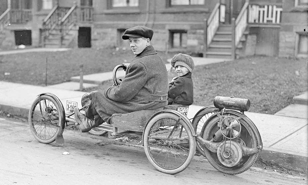
| Left: The Smith Flyer: 1917
The Smith Flyer was a four-wheel buckboard with a Smith Motor-wheel attached at the back. It seems to have been intended for fun rather than serious transport.
Nonetheless, I feel obliged to point an obvious snag. The fifth wheel is clearly hinged to the back of the vehicle, to allow it follow irregularities in the road. Thus only the weight of engine and one wheel is available for adhesion. The traction abilities must have diabolical.
It is often cited as the cheapest car ever sold, but that means stretching the definition of 'car' to breaking point. It was no competition for the Model-T Ford, which could be had for a few hundred dollars more.
|
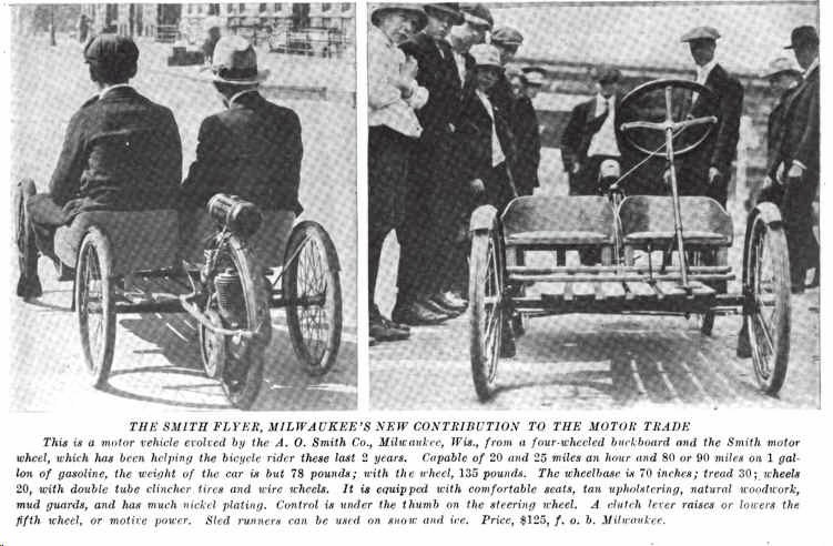 |
| Left: The Smith Flyer: 1917
The caption is informative. However, in the list of its desirable features (I like the 'natural woodwork') there is no mention of... brakes. There is no mention of suspension either; there wasn't any beyond the flexing of the chassis. It does however have front and rear mudguards.
I marvel at the idea of raising the whole engine and wheel to declutch; this is less practical with a V8. There is no mention of a throttle control, which would have required a Bowden cable; it says 'Control is under the thumb on the steering wheel', which I take to mean an ignition cutout switch. And there certainly wasn't a gearbox.
Sorry about the moire. Nothing to be done at this stage.
|
 |
|
Above: The Smith Flyer: 1917
This magnificent photograph captures a Smith Flyer superbly. The Smith Motor-wheel with its distinctive two mounting horns, has in this case a belt-driven 4-blade cooling fan.
The diagonal wire attached to the engine is presumably the 'clutch control' for raising the engine and wheel off the road.
|
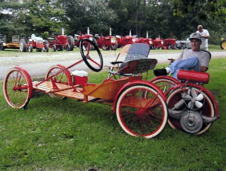 |
| Left: A Smith Flyer: picture date unknown
Pictured at what appears to be a tractor rally. This restored Flyer has a 5-blade belt-driven cooling fan.
|
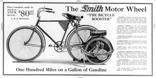 |
| Left: The Smith Motor Wheel: 1914
This shows the conventional application of the Smith Motor Wheel; you bolted it to the side of your bicycle converting it into a sort of tricycle. The Smith Motor Wheel first appeared in 1914.
The Smith Motor Wheel was an ingenious design. The disc wheel was driven directly from the cam-shaft, which was geared down 8:1 to give a suitable drive ratio. However the camshaft of a 4-stroke engine must rotate at half engine-speed; Smith got round this by having four lobes rather than one on each cam. This ingenious idea was borrowed from the Wall Motor Wheel, invented in England in 1910, of which Smith had bought the US manufacturing rights. The Wall Motor Wheel used a 4:1 reduction ratio and a two-lobed exhaust cam; the inlet valve was automatic.
|
5 WHEELS: SIDEWAYS PARKING IN 1924
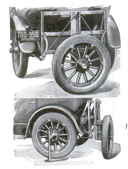 |
| Left: Parking with a fifth Wheel: 1924
Once again an earlier implementation of five-wheel parking has been discovered. Lowering the fifth wheel and turning it in either direction was done by wire cables and a pulley on the engine. No further details currently known.
Source: Popular Mechanics for Dec 1924, p892
|
5 WHEELS: SIDEWAYS PARKING IN 1933
 |
| Left: Parking with a fifth Wheel: 1933
It has emerged that the Brookes Walker Fifth Wheel (see just below) was not the first of its kind. This picture is taken from a video posted on Facebook by Road & Track magazine. The mechanism is activated by the driver pulling a rod out of the dashboard. Quite what is activated is currently unknown, but probably hydraulics. Close examination shows that the fifth wheel is driven by a chain.
The mechanism works quickly and smoothly, and looks like a first-class job of engineering.
You can see the video here.
The only information in the soundtrack is that the inventor lived in California; this is confirmed by the licence plate, which also gives the date of 1933. The car is a four-door Packard.
|
 |
| Left: Parking with a fifth Wheel: 1930s
The activating control pulled fully out of the dashboard.
|
5 WHEELS: THE GIANT AIRWHEEL
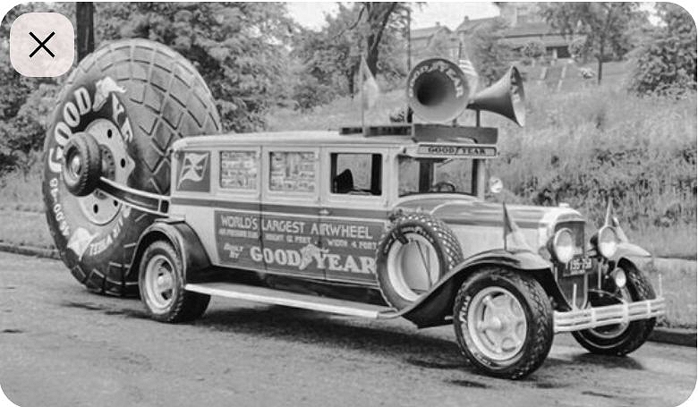 |
| Left: A Goodyear publicity stunt with a giant wheel: date unknown
I for one declare this to be a 5-wheeled vehicle. The enormous wheel was probably made for giant earth-moving trucks.
Note the two public-address loudspeakers.
Note also the small wheel attached to the arm holding the big wheel. It's too small to be an extra spare for the car, and its purpose is enigmatic.
Source:
|
5 WHEELS: A RACING CAR SAFETY FEATURE
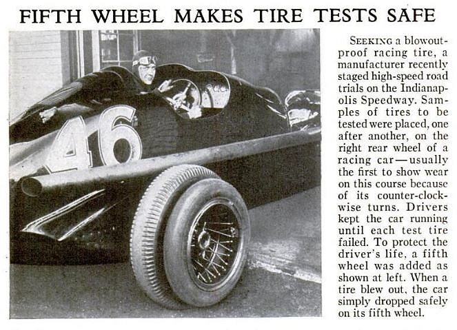 |
| Left: Fifth Wheel for safe tyre testing: 19
The text pretty much says it all.
I'm not wholly convinced this was a safe way to carry on.
Source: Popular Science July 1933, p12
|
5 WHEELS: SIDEWAYS PARKING IN 1938-1952
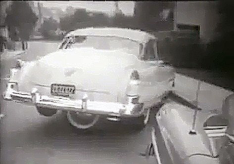 |
| Left: The Brookes Walker Fifth Wheel: 1950s
The huge barge-like cars produced in the USA in the 50's were hard to park in spaces of limited size. Here is one attempted solution; a fifth wheel that lefts the normal rear wheels off the road and allows the back of the car to go sideways. It could be argued that the car was a three-wheeler during this operation, as only three wheels were actually touching the road. A hydraulic cylinder lowered the fifth wheel, which was then rotated by a friction roller driven from the rear axle.
For a long time nothing was currently known beyond the existence of this photograph. It can now be revealed that this Cadillac is using the Park-Car concept invented by Brooks Walker in the 1930s. US patent 2,139,341 was applied for in 1932 but only granted in 1938.
Now you may object to carrying around the weight of an extra wheel just to help with parking. But the beauty of the concept is that it doubles as the spare wheel, and the only extra weight is that of the raise/lower mechanism.
There is a video of the fifth wheel in operation on YouTube.
|
 |
| Left: US patent 2,139,341, granted 1938
The fifth wheel 22 swings down on a radius arm 25, actuated by the hydraulic cylinder 31. The big spring 38 looks as if it is intended to retract the fifth wheel if the hydraulics fail.
The fifth wheel is driven by friction roller held against its tread; this is driven by the chain 45, from the shaft 43. This shaft is driven by another friction roller 41 bearing on the rear tyre 40.
I have my doubts about this drive system:
- There are two friction rollers here that need to have a good grip on their respective tyres. How well is that going to work in the wet?
- The friction roller 41 bears not on the tread of its tyre but on its sidewall. Tyre sidewalls are not designed for that sort of duty and would quickly wear and become dangerous- on the inside sidewall which is hard to inspect.
- Finally, what about the differential? Once both rear wheels are of the ground, trying to apply power through tyre 40 is just going to make the opposite rear wheel spin uselessly.
|
 |
| Left: The Fifth Wheel: 1950s
This installation takes up most of the room in the boot (trunk) and apparently the petrol tank has also had to be moved- quite a major rebuild.
From a Life article, 17 Nov 1952 (The issue that reported the victory of Eisenhower over Adlai Stevenson)
|
 |
| Left: The Fifth Wheel: 1950s
This photograph shows chain drive to the fifth wheel, alleged taken from the propellor shaft, though it is far from clear exactly how that worked.
Not to be pedantic, but I can only see one hydraulic cylinder here, at bottom right. The other tubular things are parts of the bracket holding the fifth wheel.
From the Life article of 17 Nov 1952
|
 |
| Left: The Fifth Wheel: 1950s
From the Life article of 17 Nov 1952
|
 |
| Left: The Fifth Wheel: 1950s
Multiple-exposure photography demonstrates the parking process. The car on the left can get into a much smaller parking space by swinging its rear in.
From the Life article of 17 Nov 1952
|
 |
| Left: Fifth Wheel: 1953 Packard
This 1953 Packard Cavalier was converted by Brooks Walker and used as his personal transportation; it still survives. This time the fifth wheel lives outside the boot, (trunk) which leaves the luggage space intact. Presumably moving the petrol tank was also not necessary. Definitely a more practical proposition.
|
 |
| Left: The Fifth Wheel: 1953 Packard
According to the latest information I can find, the Packard is currently owned by William Swaney of Pennsylvania, who bought it in December 2005. The hydraulic system has been rebuilt, and is fully operational, so the car can go round in complete circles if the owner so desires.
|
5 WHEELS BY HOBART BROWN- THE LOWELL KINETIC SCULPTURE RACE: 1969
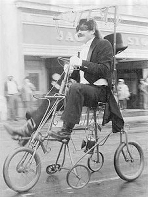 |
| Left: Five-wheeler by Hobart Brown: 1969
The first Lowell Kinetic Sculpture Race was held in 1969 in Ferndale, California. Local artist Hobart Brown modified his son Justin's tricycle by adding two more wheels, though it's hard to see much trace of a tricycle here apart from the two big wheels. There is pedal drive to the front wheel by a chain.
The little wheel at the back seems to be collapsing under the strain.
There was a 2003 article on Hobart Brown in the North Coast Journal.
|
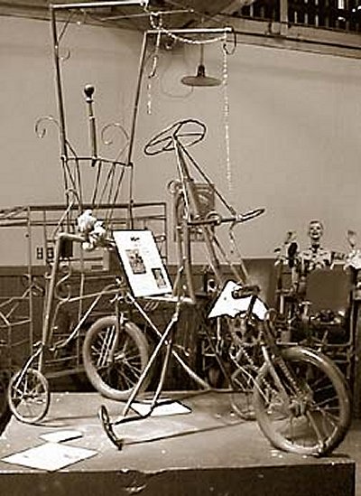 |
| Left: Five-wheeler by Hobart Brown: 1969
The Brown pentacycle is preserved in the a kinetic sculpture museum. I think it's this one.
That bent wheel still hasn't been fixed. Perhaps it's part of the artistic effect.
|
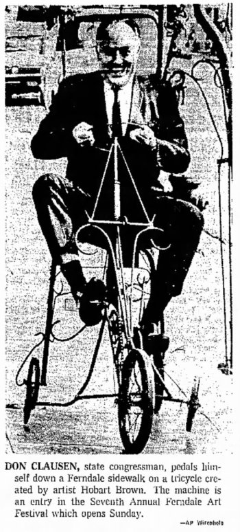 |
| Left: Five-wheeler by Hobart Brown: 1969
The caption says it all.
Don Clausen has a Wikipedia page.
|
5 WHEELS BY ZARKA AND VINCENT LAMOUROUX: 2001
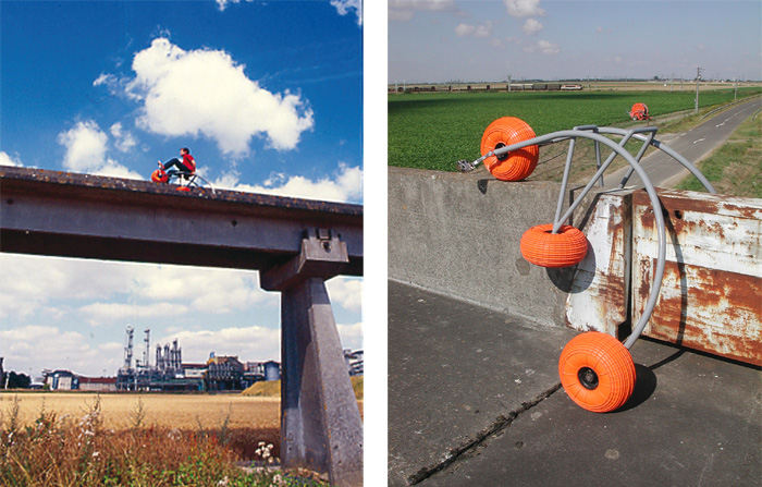 |
| Left: Five-wheeler by Raphael Zarka and Vincent Lamouroux: 2001
This pentacycle was designed with one specific application in mind; it was to ride along the abandoned track of the French Aerotrain project. It does look as if this is a unique case where five wheels really are required. Two of the balloon-like wheels support the rear of the pentacycle on the ground, while the single wheel at the front supports it on top of the big concrete rail. The two wheels on vertical axles guide the pentacycle laterally.
There is more info here.
|
5 WHEELS BY MICHAEL SALERNO: 2008
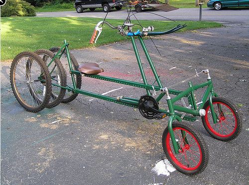 |
| Left: Five wheeled bike built by Michael Salerno: 2008
The machine was in course of construction by Michael Salerno when this photograph was taken; the chain is missing. A sequence of photographs describe the construction process on Flickr.
There seems to be no suspension so the question arises of how often all five wheels will be touching the ground.
This image is also on a site promoting the music of Jaapur and Machoo here. They have a track called Pentacycle. Don't listen it, it's bad. In fact, it's terrible.
|
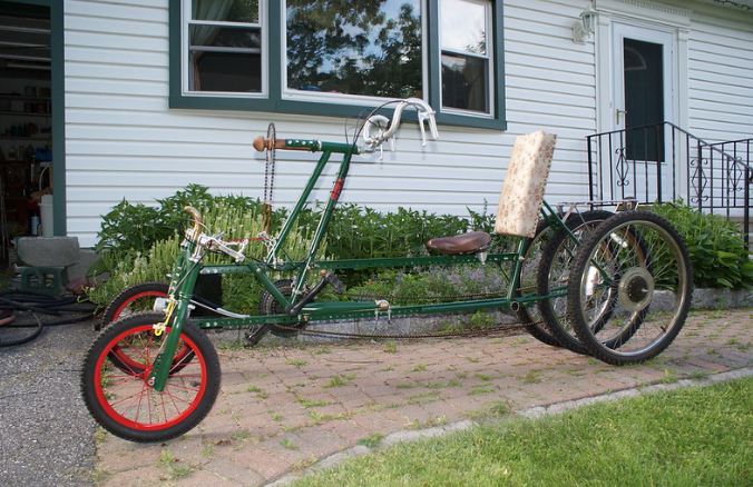 |
| Left: Five-wheeler by Michael Salerno: 2008
The machine in one version of 'finished', with handlebars. They were later replaced by a miniature ship's wheel.
Note the fancy backrest.
|
5 WHEELS IN EGYPT: 2014
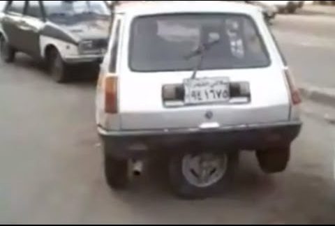 |
| Left: The Brooks Walker idea reborn.
This modification was done in Egypt. The car is an old-style Renault 5. I use to have a Renault 5TS, and it was a good and fast car. But I was tempted away by the Peugeot 205 GTi; (1.6 litre version) lovely car, wish I still had it.
There is a video of the fifth wheel doing its stuff on YouTube. It was uploaded in 2014
|
The more fastidious of readers may be complaining at this point that the Brooks Walker fifth-wheel and its Egyptian successor may be using a bright idea, but it does not have all five wheels on the ground at the same time, and so does not count as a five-wheeled car any more than does a four-wheel car with a spare wheel in the boot. See if I care.
Be aware that the term 'fifth wheel' is often used to describe the horizontal turntable on which an articulated trailer pivots. See Wikipedia.
There is also the idiom "About as much use as a fifth wheel." which makes no sense because there are times when a spare wheel really comes in handy.
5 WHEELS IN VIETNAM: 2016
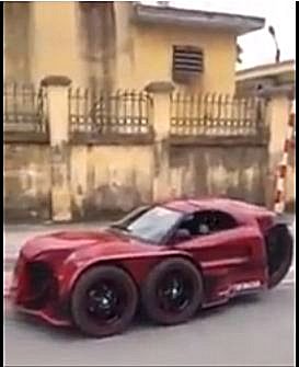 |
| Left: Five wheeled car in Vietnam: 2016
Nothing is known about this vehicle except the video on YouTube, entitled '5 wheel super-car of the man Vietnam', which presumably at least locates the country. At any rate they drive on the right. If anyone knows any more I would be glad to hear it.
There is a video of the car driving off at YouTube. It sounds like it's powered by a motorcycle engine.
Date of construction currently unknown. The video was posted in May 2016
|
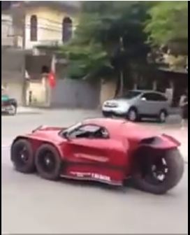 |
| Left: Five wheeled car in Vietnam: 2016
The back wheel looks like the rear wheel from a heavy motorcycle to me.
|
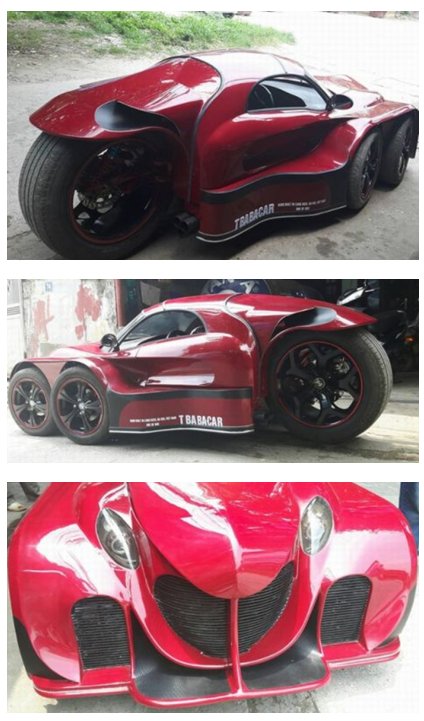 |
| Left: More views of the Vietnamese five-wheeled car: 2016
This article (dated 15 May 2015) when translated, says the builder is a Mr. Nguyen Van Thang, who apparently has no formal engineering or mechanical training.
A distinctly impressive achievement!
|
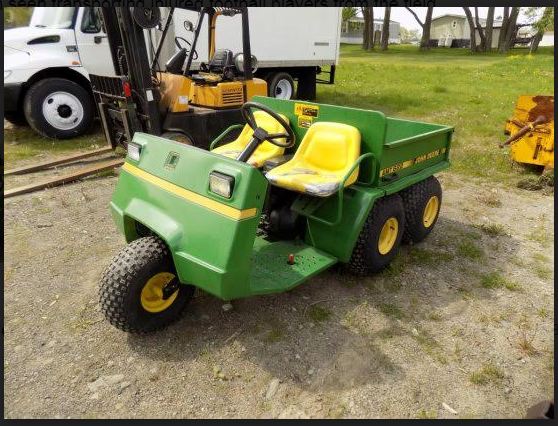 |
| Left: Five-wheeled John Deere vehicle: current
This is a John Deere Gator, in a five-wheeled version. Stu tells me it is most often seen transporting injured American football players from the field. Gator are made in a variety of configurations, with either four, five or six wheels. You can see a 5-wheel Gator in the first part of this YouTube video.
Thanks to Stu Riegel for bringing this to my attention.
|
 |
| Left: Five-wheeled cycle: current
This pentacycle certainly has five wheels. Four people are visible but it is not clear how many infants are in the trailer at the back, Twins, perhaps?
Image quality not good, I'm afraid. You have to take your five-wheelers as they come.
You can see a video of it in action on YouTube.
|
6 WHEELS
6 WHEELS: ARTICULATED CARRIAGE PULLED BY HEILMANN TRACTOR: 1898
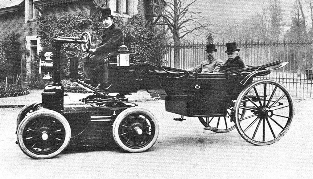 |
| Left: Carriage pulled by Heilmann tractor: 1898
Early cars were naturally based on horse-drawn vehicles, but this design takes that philosophy further than most. The horses are here replaced by a 4-wheel tractor unit.
This remarkable vehicle has now been identified as the landau of Grand Duke Alexis of Russia, drawn by a Heilmann electric tractor circa 1898.
That is the same Heilmann who produced a remarkable steam-electric locomotive.
|
6 WHEELS: THE PULLMAN CAR 1903
The Pullman marque was manufactured in Pennsylvania by the York Motor Car Company from 1905 to 1917.
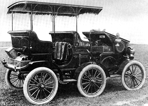 |
| Left: The Pullman car: 1903
Here's one way to arrange six wheels on a car. This wheel configuration is very rare, and was thought to be unique until the Lorraine Dietrich car (below) was discovered. When the middle wheels encountered a high spot in the road, the car had an unhappy tendency to rock back and forwards.
The Pullman car was not a success. It crashed into a telegraph pole within a year of its construction, very probably due to instability in the steering behaviour. Its parts were used in more conventional cars. The year of building is usually given as 1903, which seems to indicate it was prototype built before Pullman went into mass production in 1905.
Pullman went bankrupt and ceased operations in 1917.
|
6 WHEELS: THE PRATT CAR 1907
Charles T. Pratt of Frankfort, New York, was like Reeves, an industrialist, owning the Pratt Chuck Works. He built this 6-wheeled one-off, with a 'triple phaeton' body.
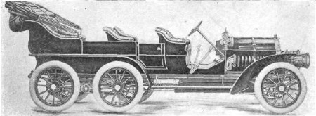 |
| Left: The Charles T Pratt car: 1907
The car was powered by an unidentified 75 HP engine. Its wheelbase - presumably measured between front and rear axles - was 168 inches. The Horseless Age wrote:
"The wheels are mounted on lengthwise members, which are pivoted to the rear springs in each side. By this mode of support much less shock is transmitted to the body of the car than is ordinarily the case, since inequalities in the road, causing a rise or depression of one of the four wheels, will raise or depress the body spring by only half that amount, provided the other wheel on the same side remains on the level."
|
|
Pratt told the press that he built the car only for his own use, but nontheless he took out two patents: US 842,245 - (Running Gear for Automobiles) in January 1907, and US 888,737 - (Automobile Running-Gear) in May 1908.
Unlike the Sextoauto, this six-wheeler apparently used both forward and centre axles for steering and the rear axle for propulsion. Since the 'centre' wheel is well towards the back this does not sound like a very practical proposition, but that is what is shown in US 842,245.
Searching for Pratt cars will only bring up George and Bill Pratt, who began car production in 1909. There appears to be no connection.
6 WHEELS: THE LORRAINE DIETRICH CAR 1908
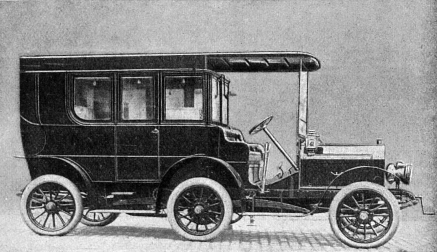 |
| Left: The Lorraine Dietrich: 1908
This six-wheeled car was produced by the Socièté Lorraine Dietrich apparently in 1908, though one source states 1903/4. The makers described it as an 'omnibus'. The rear section was stated to be a fourgon or baggage-van.
It had a 40 HP engine and a maximum speed of 55 to 62 mph (90-100 km/hr) and according to some accounts driven by the four rear wheels. This needs confirmation- the chain drive to the centre wheels can be seen just to the left of the tyre, but not so any chains to the rear axle. However if you had rear wheels, surely you would drive them? Other accounts suggest that the rear wheels were steerable, but not driven.
The first and third axles could slide axially, which was claimed to allow a very small turning-circle, equivalent to that of a car half the length. It sounds like that might make for some interesting handling. However contemporary writers enquired anxiously about the true size of its turning circle.
Just above the driver's position, a speaking tube can be seen. This allowed the passengers to give the driver instructions without the inconvenience of opening a window.
Thanks to Pavel Panenko for bringing this vehicle to my attention.
|
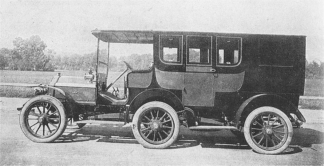 |
| Left: The Lorraine Dietrich: 1908
Another view of the Lorraine Dietrich six-wheeled car. It was commissioned by Baron Herrmann von Eckhardstein, [1864-1933] who was first secretary at the German embassy in London from 1891 to 1901. Though never the ambassador, as the first secretary he performed most of the functions of one.
The car boasted a silver sink with hot and cold running water, electric lighting and heating, and a dashboard fitted with every imaginable instrument. The fourgon actually held a fully equipped kitchen in which Emil, the chef, prepared gourmet meals. Entry to this kitchen was naturally via a tradesman's entrance at the rear of the car.
The car is said to have had a wheelbase of 3.80 metres; this is presumably the distance between adjacent axles, rather than the overall wheelbase. The six-wheel suspension was based on a patent owned by Turcat-Méry, motor manufacturers from 1899 until 1928.
|
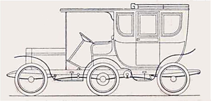 |
| Left: The Lorraine Dietrich: 1910
This diagram of the six-wheel arrangement was published in a book in 1910. There are four linked leaf-springs on each side. The inner pair of springs pivot on the chassis at their centres.
The sprocket for the chain drive is shown as a circle just to the right of the centre wheel; the chain is not shown.
|
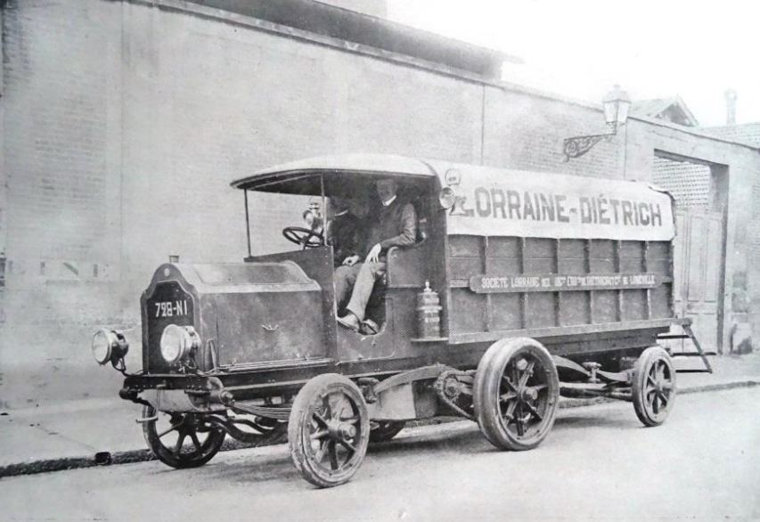 |
| Left: The Lorraine Dietrich: 1908
The six-wheeled car appears to have been preceded by this unconventional six-wheel lorry.This is one of the many Lorraine-Dietrich lorries that brought supplies to the 400,000 troops engaged in the Grandes Southwestern maneuvers in France in 1907.
The four leaf springs visible are arranged as in the diagram above; in this case the driving chain sprocket is ahead of the centre axle. No drive chain to the rear wheel is visble.
The centre wheels are bigger than the front and rear, and their tyres are bigger too, supporting the idea that only the centre wheels were driven. Also, different size wheels at the back would have required a different gear ratio to drive them. Add to this that if the rear wheels HAD to be steerable, to get an acceptable turning radius with the axle layout, applying power to them as well is going to give you all the difficulties of front-wheel drive technology- specifically a need for constant-velocity joints. Perhaps this is why the idea did not thrive- it limits you to just driving the centre axle, which is not going to give good traction.
|
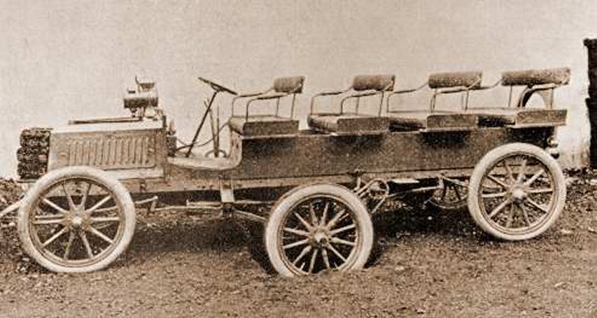 |
| Left: Turcat-Mery six-wheel charabanc: 1905
This six-wheel prototype was built by Turcat-Méry in 1905. The patent involved was actually granted to Charles Lindecker of Briancon in France. Presumably Turcat-Méry had bought the patent or taken out a licence to exploit it.
This photograph shows the middle axle in a hole; note how the inner ends of the springs on the front and rear axles have been raised, reducing the load on them.
|
 |
| Left: Six-wheel suspension from Charles Lindecker's US patent 838,343: 1906
The patent shows four methods of interconnecting the suspension of the three axles so that they will take equal shares of the load even if the ground is uneven; all are the same in principle but the fourth method, shown here, is the simplest mechanically, and the one used by Turcat-Mery and Lorraine Dietrich.
Here the springs 4 do double duty as balance levers, transferring loads to and from the front and rear axles; they are pivoted on the chassis at their centres, indicated by two small circles. The centre axle is located by the radius arm 9; when the centre axle encounters a hole, it tends to sink, which causes springs 4 to swivel on their pivots and raise the inner ends of springs 3 by means of the little links. This reduces the load on the front and rear axles.
The load distribution could be changed by varying the lengths of the suspension components.
|
6 WHEELS: THE SEXTOAUTO 1912
The Reeves Sexto-Auto actually came after the Reeves Octo-Auto, described below. Faced with no orders at all for the Octo-Auto, Reeves claimed he could "Get as good results with six wheels as with eight" which rather invites the question of why he used eight in the first place. The Sexto-Auto involved rather more rebuilding than just removing the Octo-Auto's front axle, as the axle behind it has been moved forward to a position under the radiator.
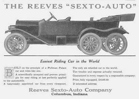 |
| Left: The Reeves Sexto-Auto: 1912
I am very doubtful if 'Tire trouble and expense actually reduced' was a realistic claim.
|
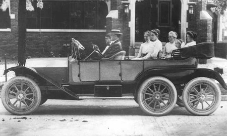 |
| Left: The Reeves Sexto-Auto: 1912
The only Sexto-Auto ever built.
|
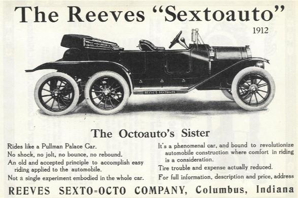 |
| Left: The Reeves Sexto-Auto: 1912
It's all very well claiming that there is 'No shock, no jolt, no rebound', but how is that actually accomplished? Even if we accept that four wheels at the back give a much superior ride, the front two wheels are entirely conventional and so you would presumably get the usual amount of shock, jolt, and rebound from them.
|
6 WHEELS: THE MELBOURNE FIRE ENGINE: 1916
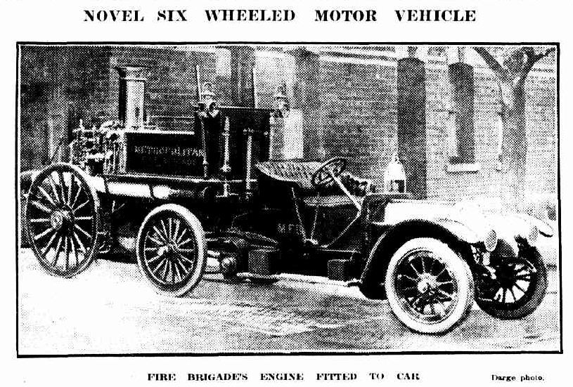 |
| Left: Horse-drawn Melbourne fire engine converted to motor drive: 1916
This bizarre vehicle was built by shortening a heavy touring car, by moving its rear axle to just behind the gearbox, removing the rear wheels, and fixing it to the chassis side-members. The rear springs were reversed and rested on the front axle of the fire engine. That is the middle set of wheels visible; they were chain-driven from what had been the car rear axle.
The original front axle of the fire-engine swivelled, and this was presumably retained to avoid a long rigid wheelbase, so it was effectively an articulated vehicle. It was built because there had been a spate of serious accidents when people tried to tow fire-engines with cars.
From the Melbourne Herald (Australia) for Monday 23 Oct 1916. See here.
Thanks to Ben Hurkett for drawing this to my attention.
|
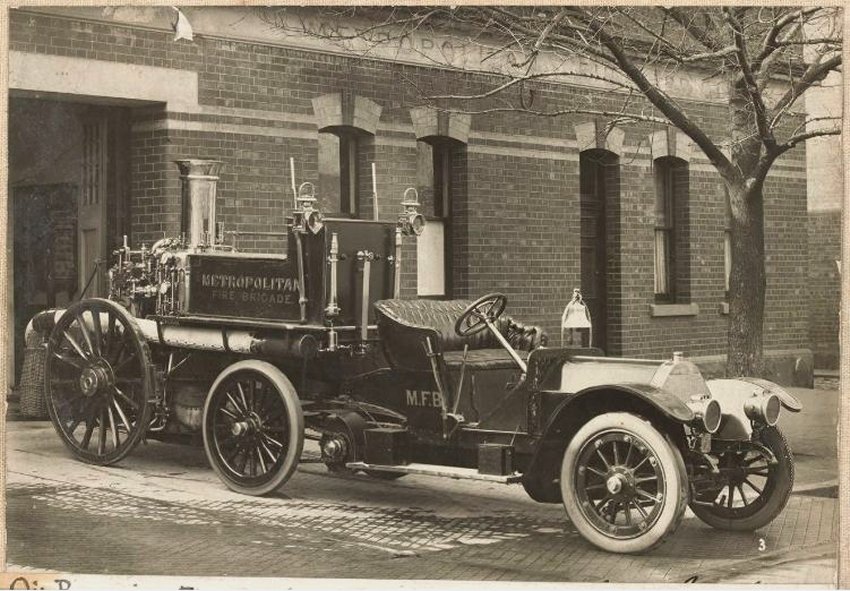 |
| Left: Horse-drawn Melbourne fire engine converted to motor drive: 1916
Here's a rather better picture that hasn't been through newspaper rotogravure.
|
6 WHEELS: THE CLARIN-MUSTAD: 1917
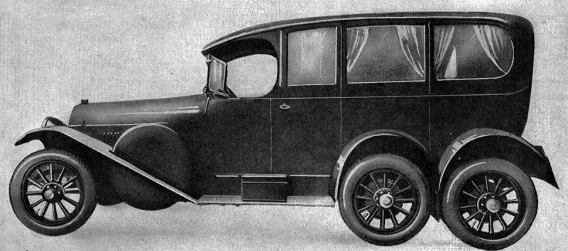 |
| Left: The Clarin-Mustad: 1917
This Norwegian car was a one of two six-wheelers built in the years 1916-1917 by Hans Clarin Hovind Mustad, one of the earliest automotive pioneers in Norway.
The front wheels steered, the middle wheels were both steered and driven, and the rear wheels simply driven. This car is supposed to be the first to be fitted with directional headlights swivelled by the steering, though it is not mentioned on the Wikipedia page.
The wheelbase between the front and rear axles was 4.37 m and the weight was about of 3 tons.
One of these cars is said to be in the Norwegian Museum of Science and Industry in Oslo, though it appears not to be viewable on their website.
|
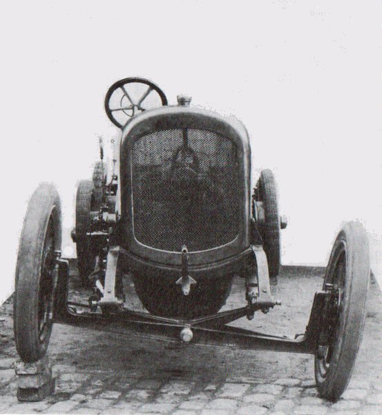 |
| Left: Clarin-Mustad chassis: 1917
Yes, it can deal with three bricks.
The Clarin-Mustad shamelessly displays its front beam axle. Such axles were common in early cars because of their simplicity, but the disadvantages are the lack of independent wheel movement and the high unsprung weight as the whole axle is unsprung.
|
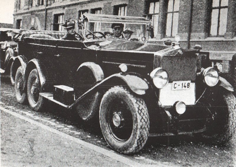 |
| Left: Open Mustad car: 1927
|
6 WHEELS: THE HISPANO-SUIZA H6A: 1922
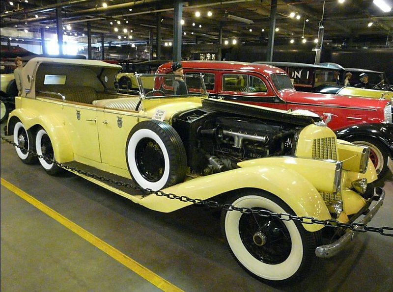 |
| Left: The Hispano-Suiza H6A: 1921
Based on the standard H6 Hispano-Suiza, this unique car was built for Constantine I, the King of Greece. Regrettably he had to abdicate in 1922 before taking delivery, and it was bought by the film director D. W. Griffith for $35,000. It appeared in the 1933 film "My Lips Betray" and some war films. It is now at the Forney Museum in Denver.
The car is believed to have been built in Barcelona, and the body designed and built by Leon Rubay.
The H6 in general has a Wikipedia page.
|
6 WHEELS??: THE FRENCH AMC SCHNEIDER P 16: 1925
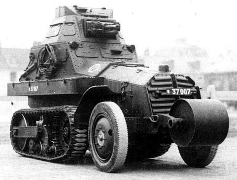 |
| Left: The AMC Schneider P16: 1925
I don't think there is any rational way you could call this a 6-wheeled vehicle, but the very prominent nose-roller on this half-track relates to the French vehicles further on in this section. Of course once you let in tracked vehicles, you could have endless discussions as to whether you should count just the big wheels/sprockets at each end or all of the track roadwheels as well. Let's not bother.
The P16 was developed in 1924 by Citroën from the earlier Citroën-Kégresse Modèle 1923. Both employed the Kégresse track, A Kégresse track uses rubber or canvas in a continuous flexible belt rather than interlocking metal segments, as in conventional tracks. Adolphe Kégresse was a French military engineer.
This half-track was classified by the French as an armoured car rather than a tank.
|
6 WHEELS: THE GAZ-21 6X6 PROTOTYPE: 1927
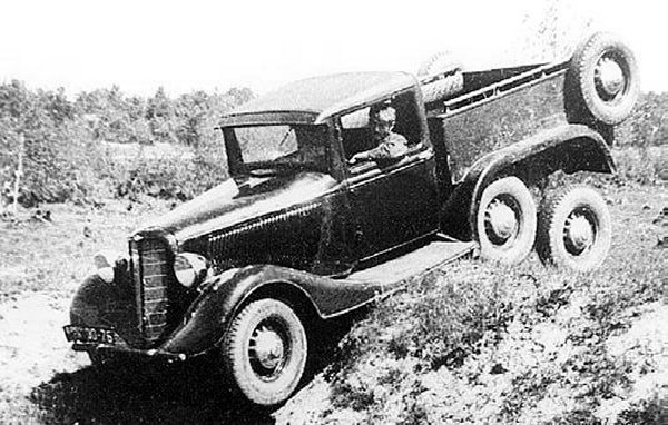 |
| Left: The GAZ-21 6x6 prototype: 1927
The GAZ-21 6x6 was a Russian off-road prototype based on the GAZ-21 civilian saloon car. Very little information is available.
Referring to Wikipedia's List of GAZ vehicles we also find the GAZ-AAA - 6x4 2-ton truck, produced from 1934 to 1943. It was a three axle version of the GAZ-AA.
|
6 WHEELS: THE MERCEDES-BENZ G4 W31: 1934
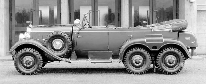 |
| Left: The Mercedes-Benz G4: 1934
The Mercedes-Benz G4 Type-W31 was a six-wheeled staff/command car built for the Wehrmacht in 1934, designed to cope with off-road conditions. Only 57 were built, of which only three completely original specimens are known to exist, one of them belonging to the Spanish royal family.
All versions had eight-cylinder inline engine, driving the rear four wheels through self-locking differentials. The rear wheels were attached to two rigid axles suspended by semi-elliptic leaf springs. The first three years of production had 5018 cc engines delivering 100 HP. Later engine capacity was increased to 5252 cc and then 5401 cc.
This car has a Wikipedia page.
Thanks to John Bevan for drawing this car to my attention.
|
6 WHEELS: THE LORRAINE MILITARY VEHICLES: 1931/34
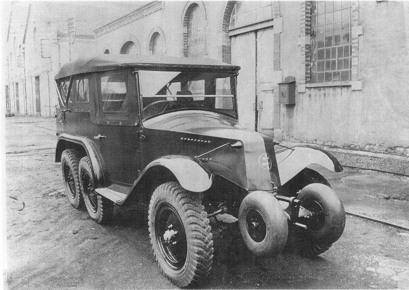 |
| Left: Lorraine-Dietrich VLTT 72: 1931
It should be simple enough to say how many wheels a vehicle has; and then you come across something like this. Does this count as six wheels or eight?
This vehicle is a VLTT (Voiture de Liason Tout Terraine) Lorraine 72, built under licence from Tatra by Lorraine-Dietrich for the French forces. Images of this vehicle and others with the same chin-mounted axle are not hard to find if you know what you are looking for, but nonetheless none of the sources examined by the Museum staff even mention the very obvious extra wheels. It appears the idea is to make crossing ditches easier, as the extra wheels would help the front of the car to rise up the far side of the ditch.
Presumably the two chin wheels were not powered, as they have no tread on; they are purely to stop the vehicle burying its nose in the ground. There also appears to be no room under the extended starting-handle for any drive mechanism.
We have met the Lorraine-Dietrich company before, making six-wheeled lorries. See 1908 above.
|
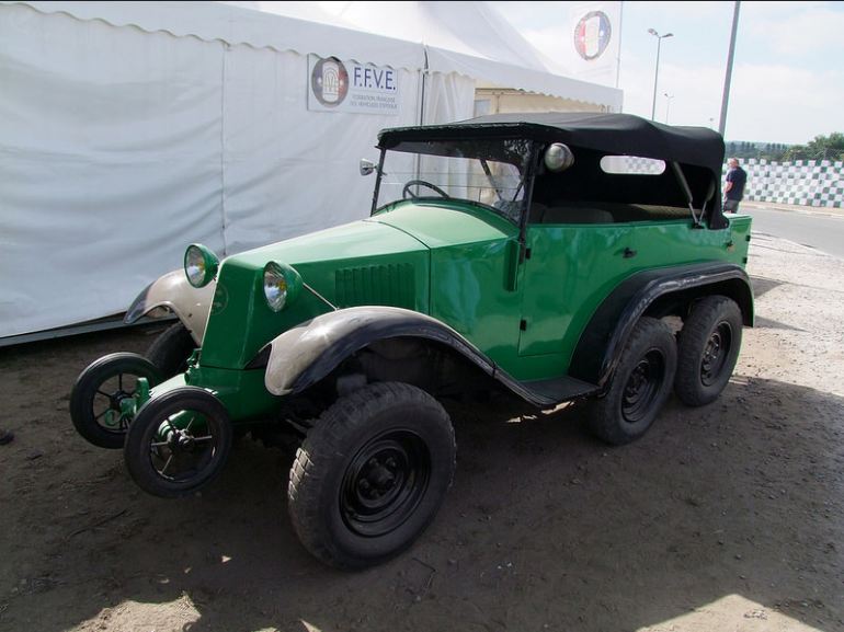 |
| Left: Lorraine-Dietrich VLTT 72: 1931
At least one VLTT 72 has been preserved; location and date of photo not currently known.
|
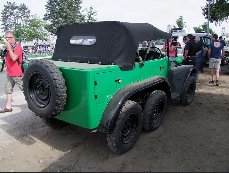 |
| Left: Lorraine-Dietrich VLTT 72: 1931
The rear of the preserved VLTT 72.
|
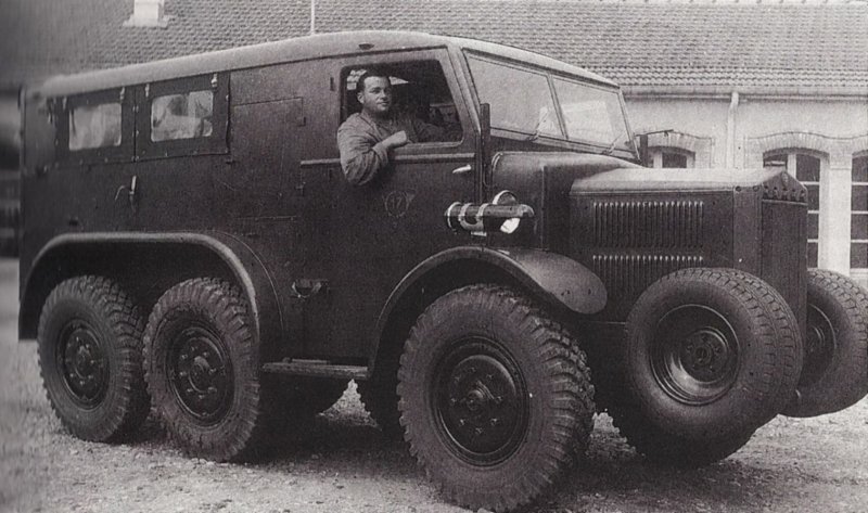 |
| Left: Lorraine-Dietrich VDP 24: 1934
This vehicle, a fast troop transporter, was also built under licence from Tatra. Testing began in 1934 and the VDP 24 was issued to the services in 1937.
Now there are four wheels on the chin axle, much more heavily constructed. So is that six wheels or ten?
Here the chin wheels are treaded. It is not currently known if they were powered.
The weight was 3.78 tonnes loaded and 2.72 tonnes empty. Length was 4.84m and height 2.08m. Ithad a four-cylinder engine of 4710 cc giving 55 HP and a maximum speed of 65 km/hr. It could carry ten men in total. It had no built-in armament but two hatches in the roof allowed for possible mounting of AA guns.
VDP srands for 'Voiture de Dragons Portés' which Google translate renders as 'Car of dragons worn'; this is unhelpful. I think it means 'car for mechanised dragoons'.
|
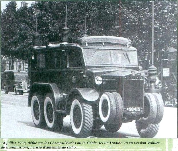 |
| Left: Lorraine-Dietrich 28: 1938
The Lorraine 28 radio truck was a variation on the VDP 24. Here is one taking part in a parade in Paris in the ominous year of 1938. Note white-wall tyres on both the big and the little wheels.
An inherent problem with this idea is the need to carry around two sizes of spare wheel.
|
6 WHEELS: THE SKODA 903 1936
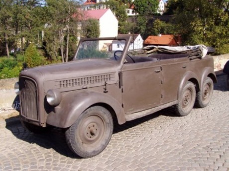 |
| Left: Skoda 903: 1936
This military vehicle, the Skoda 903 (page in Czech) was developed from the Skoda Superb. (1934-1949) for the Czech Army. Three were built initially; a later version was built in 1939, totalling 42 vehicles..
The
Skoda plant at Mladá Boleslav is the largest production plant in the Czech Republic.
|
6 WHEELS: THE GAZ-AAAA Prototype: 1936
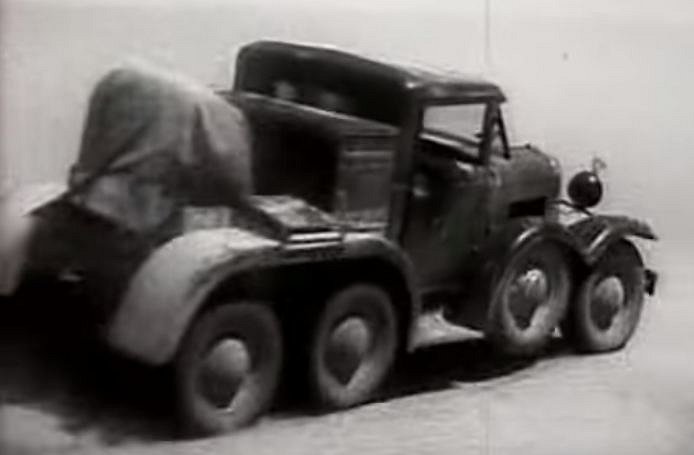 |
| Left: GAZ-AAAA prototype: 1936
This Russian military prototype, the GAZ-AAAA, had six normal wheels plus two more just behind the front pair. Images of this vehicle are very rare, but there is a YouTube video that shows the GAZ-AAAA in action for a few seconds around 38:35, and this image is taken from there.
Presumably the extra two wheels are spares; those carried on the middle and heavy Einheits-PKW did double-duty as while they did not normally contact the road, they stopped the vehicle grounding on humps. These extra wheels are close behind the front pair and it is hard to see how they could have fulfilled an anti-grounding function.
Referring to Wikipedia's List of GAZ vehicles it appears that only one prototype was built.
|
6 WHEELS: MOTORCYCLE CHARIOT RACING: 1936
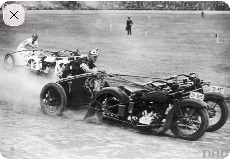 |
| Left: Motorcycle chariot racing In Australia: 1936
This extrordinary event is a chariot race, with each chariot pulled by two motorcycles.
This was part of celebrations by New South Wales police in Australia in 1936. Before I stumbled on this picture I had never heard of such a thing.
The first motorcycle chariot race was staged in 1922 in Oakland, California. After the release of the film Ben-Hur: A Tale of the Christ in 1925, interest in chariot racing was greatly stimulated.
I cannot identify the make of motorcycle, but the engine looks like a V-twin, so they may be Harley-Davidsons.
Quite clearly a six-wheeled vehicle.
|
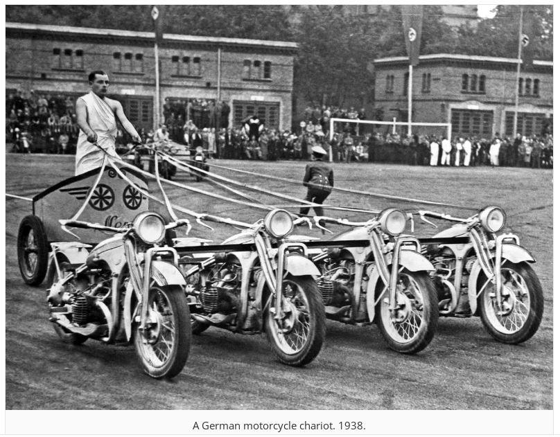 |
| Left: Motorcycle chariot in Germany: 1938
This four-in-hand chariot was exhibited in Germany in 1938. It's not clear if this is actually a race, as no other competitor is visible. But there is no doubt that there are four motorcycles there, giving a total of 10 wheels. They are joined together by three horizontal bars.
Possibly I should put this in the 10-wheel section, but it seems a better fit here. There will be a link to here in the 10-wheel section.
I think the steering would be a bit tricky. The engines appear to be horizontal twins, so the motorbikes are probably BMWs.
Unexpectedly, motorcycle chariot racing has a Wikipedia page.
|
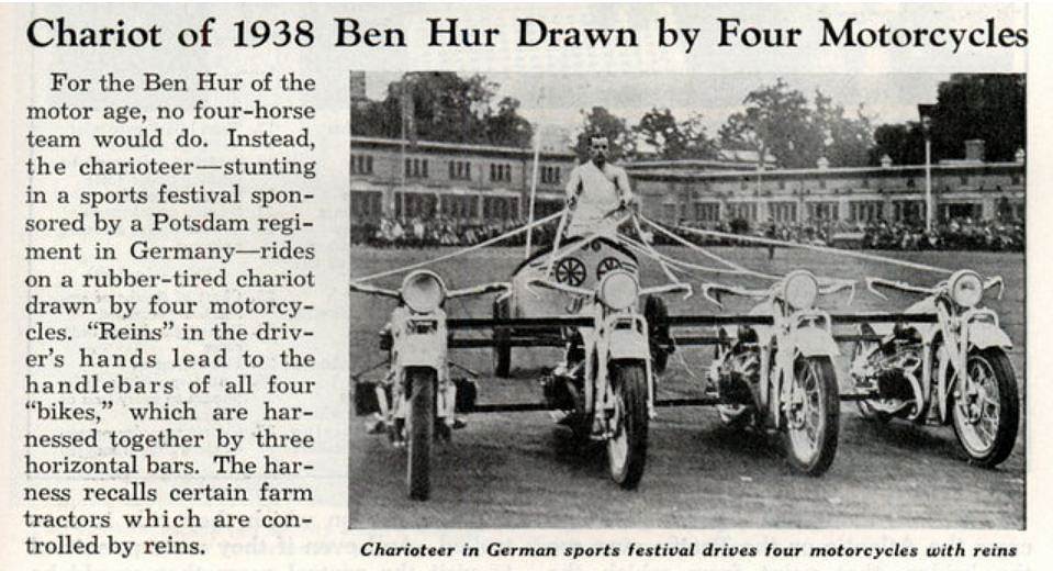 |
| Left: Motorcycle chariot in Germany: 1938
This is another view of the four-motorbike chariot. Still no other contestant in sight.
Note the very relevant reference to Rein-Guided Tractors at the end.
|
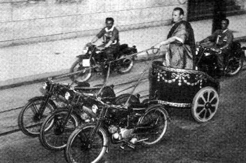 |
| Left: A three-motorcycle chariot: 19??
Three motorcycles for a total of eight wheels.
Nothing is known about this image. Can anyone help?
|
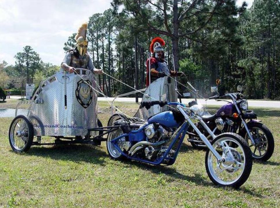 |
| Left: A three-motorcycle chariot: 19??
There is very little motorcycle chariot racing going on today, but it still exists. These chaps find one motorcycle does the job.
Sparta on the left, Rome on the right. Note the engine-turned finish on both chariot bodies.
Nothing is known about this image. Can anyone help?
|
6 WHEELS: THE LAFFLY S35T ARTILLERY TRACTOR: 1937
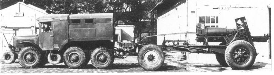 |
| Left: Laffly S35T 1937
This Laffly S35T artillery tractor also challenges definition. Do you call this six wheels or ten?
It has six normal wheels, two little wheels on the chin like the Lorrain vehicles- plus another two little wheels between the front and middle main axles, presumably to stop the chassis grounding on bumps. The first vehicles were delivered to the French army in 1937. All six of the main wheels were driven, but only the front two steered.
The Laffly Company, founded in 1912, were major manufacturers of of heavy vehicles like trucks and buses in the 1920s and 1930s. Laffly made other military vehicles with one or two extra little-wheel axles, such as the S15 and the W15 TCC.
|
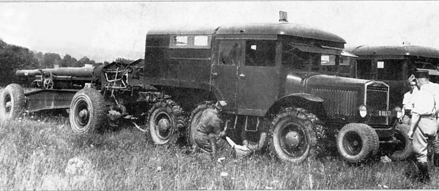 |
| Left: Laffly S35T 1937
This picture of a Laffly S35T demonstrates that there were four wheels on the chin axle. So, do you call this six wheels or twelve? I am assuming the axle under the cab carries only two little wheels because of restricted space. The little wheels had no suspension, but were rigidly attached.
This Laffly S35T is still in the hands of the French- note the caps on the men. After the fall of France they were used by the Germans.
The main wheels are here fitted with snow chains. Since it's not winter (the men are in their shirt-sleeves) I wonder if there were some traction problems.
|
6 WHEELS: THE VAUXHALL VILLIERS: 1938
Another approach to putting six wheels on your car is double tyres on the rear axle. The Vauxhall Villiers racing car had a 3000cc 300 HP supercharged engine, and dual rear wheels were tried by driver and entrepreneur Raymond Mays in the hope of better traction in hill-climb races.
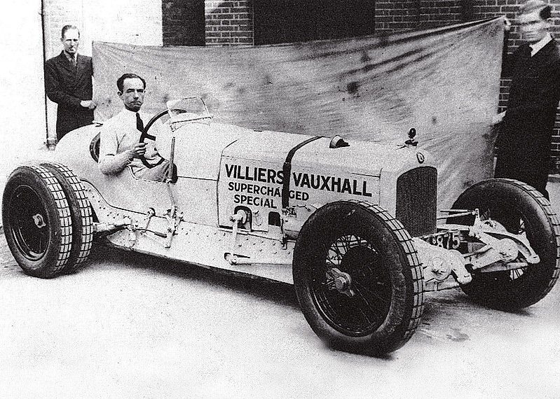 |
| Left: The Vauxhall Villiers: 1938
The Vauxhall Villiers was sucessful at hill-climbing and sprint races, but it was known to be a very tricky car to handle. Here Raymond Mays grimly clutches the steering wheel.
You could argue all day if this really counts as six wheels rather than four wheels, but let's not.
Why anyone thought that holding up a grimy sheet behind the car would make a better picture is unknown.
|
6 WHEELS: THE PAT CLANCY SPECIAL: 1948
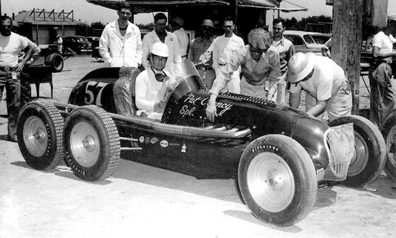 |
| Left: The Pat Clancy Special: 1948
This six-wheeled car was built to compete in the Indianapolis 500. The Clancy Special made its first appearance in the race in 1948, driven by Billy DeVore; it qualified 21st and finished 12th, 10 laps behind the winner but unquestionably a brave effort for an unconventional car.
In May 1949 it raced at the Indy 500 again, but retired after 65 laps with a broken driveshaft. It was then converted to a four-wheeler.
Pat Clancy was a Memphis trucking fleet operator. His thinking was that since dual rear axles worked well on heavy trucks, they would also work well on racing cars.
|
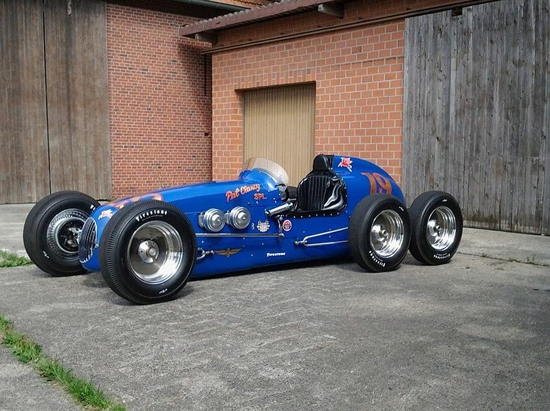 |
| Left: The Pat Clancy Special replica: build date unknown
This is a replica of the six-wheeled Clancy car, built by A J Watson. It has an Offenhauser engine.
|
6 WHEELS: THE HANNIBAL TWIN-8: 1964
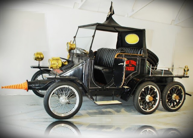 |
| Left: The Hannibal Twin-8: 1964
This is Professor Fate's Hannibal Twin-8 car from the 1965 movie The Great Race. Jack Lemmon played the evil Professor Fate, opposite good guy Tony Curtis. (I saw it when it came out and I remember it as a good film) Sources differ as to whether three, five, or six were built, which is at least two more than some of the machines in this gallery. However it seems likely that only two of the cars were fully functional.
Unusual features are that the bodywork really can be raised 9 feet above the chassis by hydraulic rams, and there was a fully functional smoke screen generator. However, the retractable brass cannon pointing out of the front is not likely to fire anything other than a small pyrotechnic, and the nose that could be made to glow red-hot (for melting snow drifts) was just a lighting effect.
This machine is worth studying, because it was rather more than just a movie prop. The Hannibal Twin-8's were custom built by Warner Bros from the ground up at a cost of $150,000 in 1965 money, which was about three times what a house went for back then. (It is not currently clear if that was the cost each or for the three; I suspect the latter)
Power is from a Corvair flat-6 with a 3-speed manual gearbox; all four of the rear wheels are powered by a chain drive. The Hannibal Twin-8 remains in its original and un-restored condition just as it was last used on the movie set. It is still fully operational, and it actually runs and drives. It even has a 1965 assigned VIN and could be titled, registered and driven over the road.
|
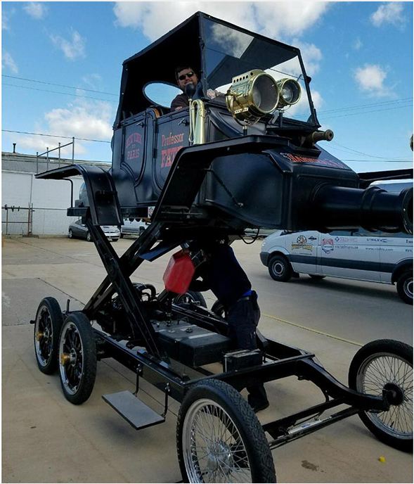 |
| Left: The Hannibal Twin-8: 1964
Demonstrating the Hannibal Twin-8's ability to rise above things. I'm not sure if you can safely do this while driving along...
An immediate question is how was it steered, when the steering wheel is up in the air. The answer probably lies in the flexible cable that can be seen running to the front axle.
The exact significance of the name Twin-8 is obscure. I seem to recall that the fictional car was supposed to have twin engnes, but attempts by the Museum staff to confirm this have so far failed. As for the '8' surely they didn't mean twin V8 engines?
There is a video of Jack Lemmon extolling the features of the Hannibal Twin-8 on YouTube. The car appears at 0:40.
|
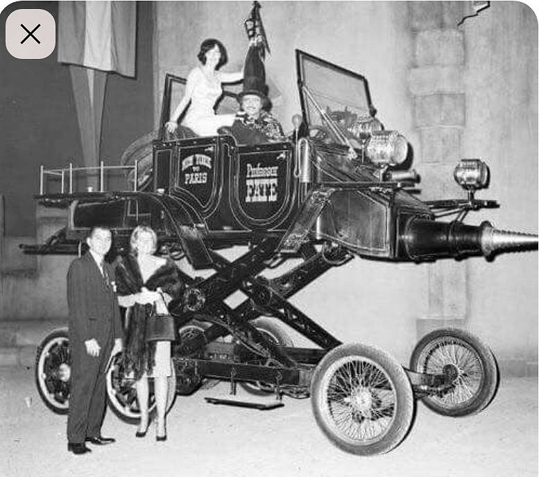 |
| Left: The Hannibal Twin-8: 1964
This looks like a publicity photo from 1965.
Note the car carries three spare wheels. You can't take chances when you're a movie villain.
|
6 WHEELS: THE RAIDERS COACH: 1969
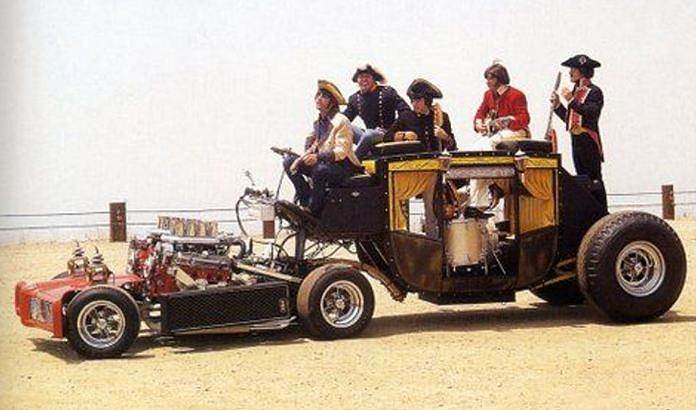 |
| Left: The Raiders Coach: 1969
This custom 6-wheel articulated vehicle was built by George Barris for the USA band Paul Revere and The Raiders in 1969. The front section carried two V-8 engines.
It is not currently known how the two engines drove the middle wheels; it seems likely that the two engines were coupled together to drive a single differential. There must have been a lot of power available, and I suspect attempting to use it would result in some interesting handling.
Barris also built the first Batmobile in 1966, and the Munster Koach.
|
6 WHEELS: THE TYRELL P34: 1975
The Tyrell P34 was a six-wheeled Formula 1 racing car first unveiled in 1975. It was first tried on the track at Silverstone on 8th October 1975. After much testing, Tyrrell decided to build two more 6-wheel cars to race in the 1976 season.
The idea behind the P34 was the use of front tyres that would fit in with the streamlining. This would have two effects; this would be to lower overall drag and also provide smoother airflow to the rear wing. The wheels were only 10 inches (250 mm) in diameter, and because of the small contact patch with the road, four were required to give good cornering.
 |
| Left: Tyrell P34 driven by Depailler: 1976
The high point of the P34 story was the 1976 Swedish Grand Prix; Jody Scheckter and Patrick Depailler finished first and second in their P34's. Scheckter remains the only driver ever to win a race in a six-wheeled car.
However various handling problems emerged and Tyrell's design for the 1978 season had four wheels. One P34 has survived and is often seen at historic racing events.
Looks like daylight under that rear wheel.
There is a Wikipedia page for the P34.
|
6 WHEELS: THE PANTHER SIX: 1977
This Six was built by the retro-sportscar manufacturer Panther, owned by Robert Jankel. Top speed was claimed at 200 mph, but Panther went bankrupt before any were sold.
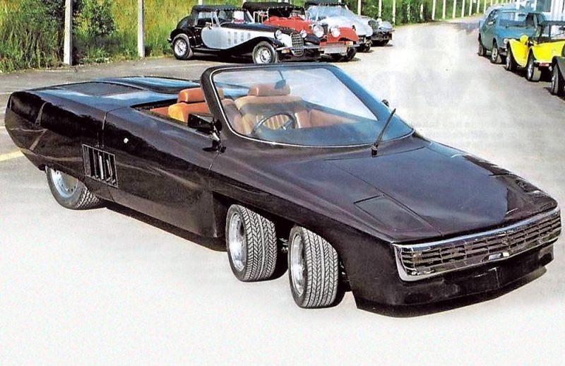 |
| Left: The Panther Six: 1977
The Panther Six is mid-engined with a 8.2 litre Cadillac V8 powerplant with twin turbochargers. Only two cars were built, one white and one in black, and both are known to still be in existence. The rear wheels are fitted with 265/50 VR16 tyres, and the two pairs of steering front wheels with 205/40 VR13 tyres. In the tyre codes the 16 and the 13 give the diameter of the wheel rim; it is therefore necessary to carry around two spare wheels of different sizes.
The Panther Six has a Wikipedia page.
|
6 WHEELS: THE WOLFRACE SONIC: 1981
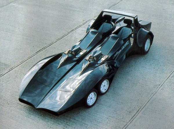 |
| Left: The Wolfrace Sonic: 1981
No, it's not the Batmobile. This remarkable vehicle was built by Wolfrace to promote their alloy wheels. And what better way to do that than produce a car with more wheels than normal?
It was powered by two Rover V8 engines, apparently controlled by a throttle-by-wire system. There was a spaceframe chassis, and rear-wheel drive through a Jaguar rear-axle and differential. Despite the immense length of the Batmobile-style body, it was only a two seater. It was designed by Nick Butler and was a big budget project costing about £100,000.
On the 2nd of March 2015 the Sonic was sold on Ebay for only £18,100 to an unknown buyer. I hope the publicity was worth the money.
I am glad to report that Wolfrace are alive and well.
|
6/8 WHEELS: THE CHRYSLER VOYAGER III: 1989
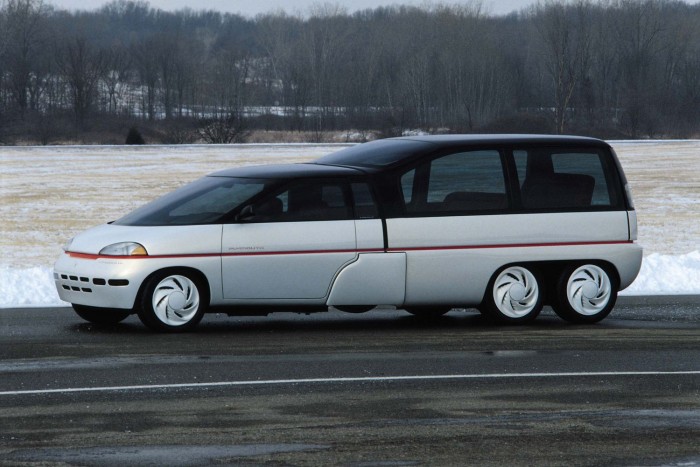 |
| Left: The Chrysler Voyager III concept car: 1989
The idea here was to combine a small car suitable for solo commuting with a big van that could haul the whole family around on vacations. It was shown at the 1990 North American Auto Show.
The front car detached and ran on four wheels; it had seating for three in individual bucket seats, arranged in a single row. (which surely must have made the 'small car' rather wide) It was powered by a three-cylinder engine fuelled by propane and driving the front wheels.
The detachable rear section provided seating for eight more passengers, making 11 occupants in all. It was to be powered an independent 2.2 litre four-cylinder engine, with the two engines were linked electronically. For maximum fuel economy, use of the rear engine was intended to be optional when the segments were joined, but it is hard to believe a three-cylinder engine could safely move the combination. When both engines were in use the two-engine configuration gave the Voyager all-wheel drive traction, so presumably both rear axles were driven.
You are probably wondering what happens to the rear wheels of the front unit; they retracted underneath the Voyager III when the two halves were joined, with aerodynamic skirts covering the open wheel wells. So... is that four wheels, six wheels, or eight wheels?
All of this was obviously heavy and expensive to manufacture, and had the crippling snag that it would certainly have been cheaper to buy a small car and a big van separately; having two complete vehicles is clearly far more flexible.
|
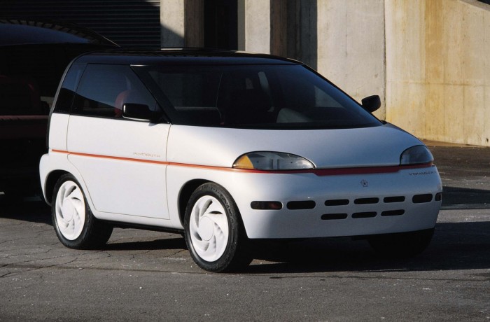 |
| Left: The Chrysler Voyager III concept car: 1989
This is the small-car section, with its rear wheels in action. It was powered by a three-cylinder engine running on propane. The wheelbase of the fully-assembled Voyager III was 122 inches, and the overall length 199 inches.
There is a Wikipedia page, where the car is referred to as 'the Plymouth Voyager 3'.
The car is referred to as the 'worst concept car of all time' here. I'm not arguing.
|
6 WHEELS: THE COVINI C6W: 2004
The Covini is a The Covini C6W is a six-wheeled Italian sports coupé. It is claimed that it was directly inspired by the 1976 Tyrrell P34 above.
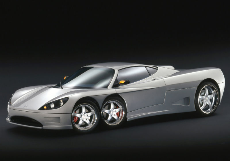 |
| Left: The Covini C6W: 2004
In 2004 the C6W was first shown in prototype form. Small-scale production began in 2005 at the rate of 6-8 cars per year, and is believed to be still continuing. The car has 4200 cc 8-cylinder engine mounted at the rear and a claimed top speed of 186 mph. The transmission is a 6-speed manual box.
|
6 WHEELS: FAB-1: 2013
Lady Penelope was the posh piece of tottie in the Thunderbirds TV show. She drove around in a shocking-pink Rolls-Royce with six wheels, usually chaffeured by Parker, a reformed burglar.
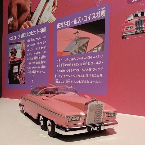 |
| Left: Lady Penelope's FAB-1: 2013
There were various versions of FAB-1; this late version is at a show in Toykyo in 2013. Note Parker driving and Lady Penelope in the back.
In case you're wondering, 'Fab!' short for 'Fabulous!' was a common exclamation in the Swinging Sixties.
|
6 WHEELS: ROAD GRADERS: CURRENT
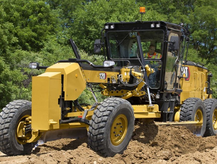 |
| Left: Six-wheeled CAT road grader: current
While they are very practical pieces of machinery, (unlike some of the examples above) road graders. usually have six wheels. A good deal of forward pushing is required, so most of the weight of the grader with its engine, etc, is above the rear four wheels, which are all driven.
There is more info on CAT road graders here.
|
7 WHEELS
 |
| Left: Car with one axle supported by a four-wheel truck: date unknown
It has taken a long time, but at last we have what can fairly be called a seven-wheeled car. Not surprisingly the man looks rather thoughtful. One hopes he was not expected to do any rear-wheel steering.
The car is left-hand drive so this is presumably somewhere in Europe, in a place where traffic regulations are not taken too seriously. Obviously it is front-wheel drive as well. Stu Riegel says it is a Lada Oka and it appears to have Russian plates.
The Oka was a reasonable cheap car, except that it was famously uncrashworthy. It was nicknamed "The Capsule of Death". In a crash test, done by by the Russian ARCAP safety assessment program, the car received a 0 stars rating out of a possible 4. Obviously these guys didn't think that that was dangerous enough.
|
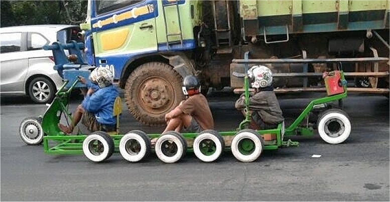 |
| Left: Seven-wheeled vehicle in Indonesia: date unknown
If you are unconvinced by the example above, here is a vehicle that has all seven wheels permanently attached. There are two wheels on the far side of the vehicle and five wheels on this side. The engine can be seen above and to the left of the rear wheel, and below the green frame. Note the petrol can.
Good to note that they are all wearing helmets.
Idiosyncratic modifications are common in Indonesia.
|
 |
| Left: Seven-wheeled mobile pump: date unknown
This mobile water-pump has one wheel at the front for steering and to support the pipe boom, while there six wheels on the axle at the back. Judging by the strainer we're looking at the suction end.
Note the white rod for steering the single front wheel.
Many thanks to Steven McDonald for drawing this machine to my attention.
|
 |
| Left: Seven-wheeled mobile pump: date unknown
The engine is cantilevered out behind the rear axle, in order to partly counterbalance the boom at the front.
The location is believed to be Thailand.
|
8 WHEELS
8 WHEELS: THE OCTOAUTO: 1910
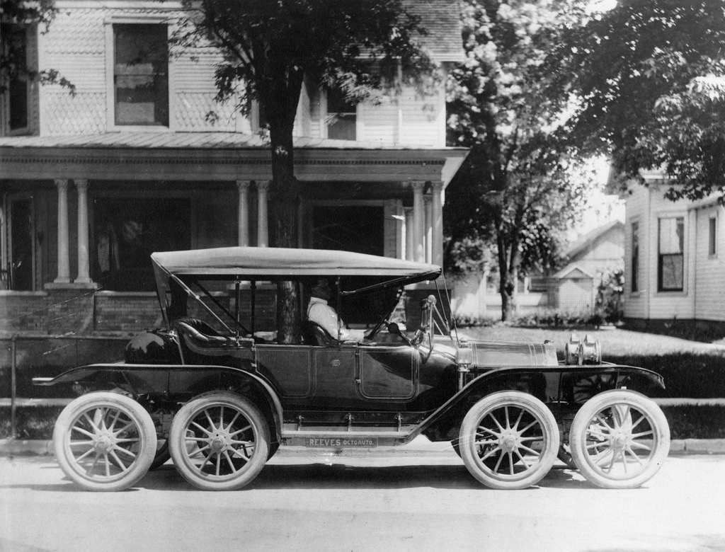 |
| Left: A magnificent photograph of the Reeves Octo-Auto: 1910
The Reeves Octo-Auto was a 1910 Overland modified by Milton Reeves. It had a 40 HP engine and was more than 20 feet long, carrying four passengers. It was a commercial failure.
Unfortunately this picture reveals nothing about how the suspension was arranged.
|
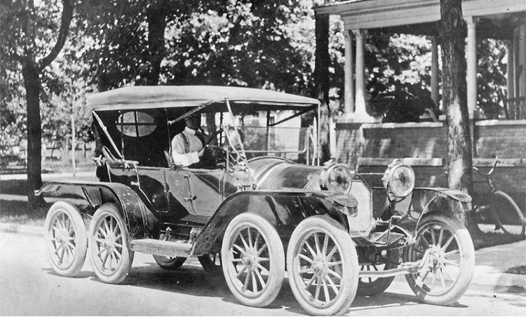 |
| Left: The Reeves Octo-Auto: 1910
This is not much more informative about the suspension, though we can see a conventional axle for the front two wheels.
Clearly taken at the same time as the photograph above.
|
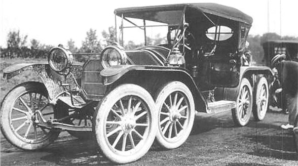 |
| Left: The Reeves Octo-Auto: 1910
This suggests that the front axle was simply held by two struts running backwards.
(see left front wheel)
|
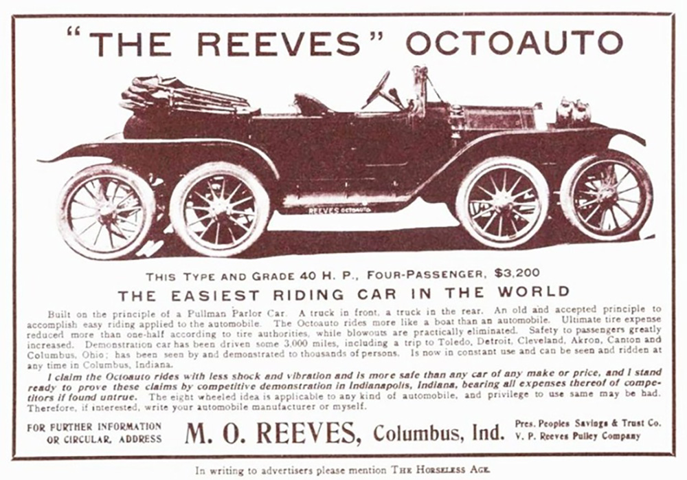 |
| Left: The Reeves Octo-Auto: 1910
The ad copy claims 'blowouts practically eliminated', though I would have thought that having twice as many tyres could only increase your chance of picking up a nail.
|
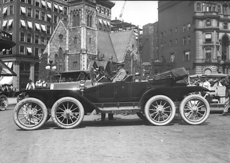 |
| Left: The Reeves Octo-Auto: 1910
Another picture of the Octo-Auto at an unknown location.
|
8 WHEELS: MERCEDES-BENX PERSONNEL CARRIER
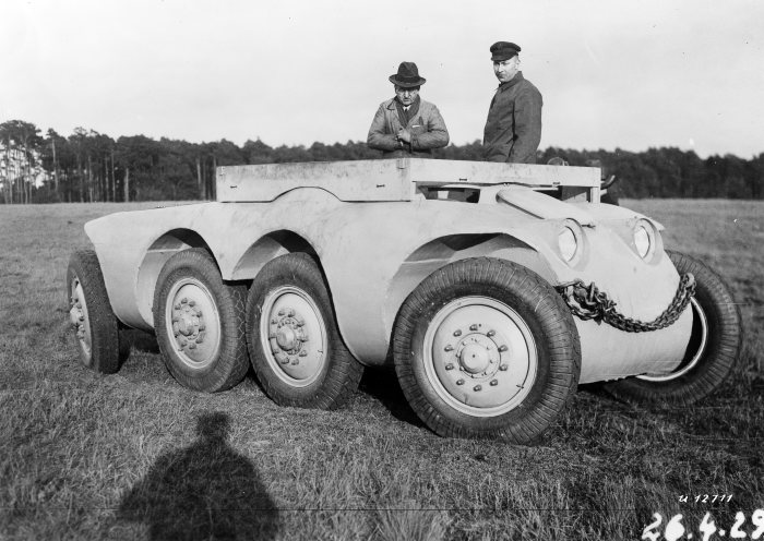 |
| Left: Mercedes-Benz eight-wheeler: 1927
The MTw 1 amphibous personnel carrier from Mercedes-Benz. All eight wheels were driven, and it looks as though both front and back wheels were steerable. This is a test chassis from 1927/28.
|
8 WHEELS: MAGIRUS PERSONNEL CARRIER
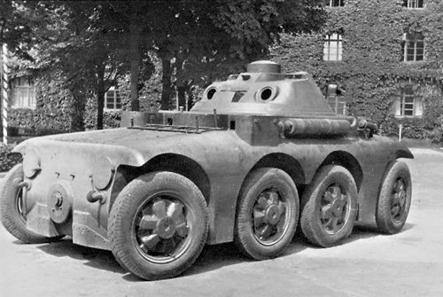 |
| Left: Magirus ARW eight-wheeler: 1927
This vehicle was designed to the same spec as the Mercedes above; it was amphibous. All eight wheels were driven, and both front and back wheels were steerable. There were once again driving positions at both front and back to facilitate rapid retreats.
It never went into mass production as it was too expensive to build.
|
8 WHEELS: THE RIMMEK CAR
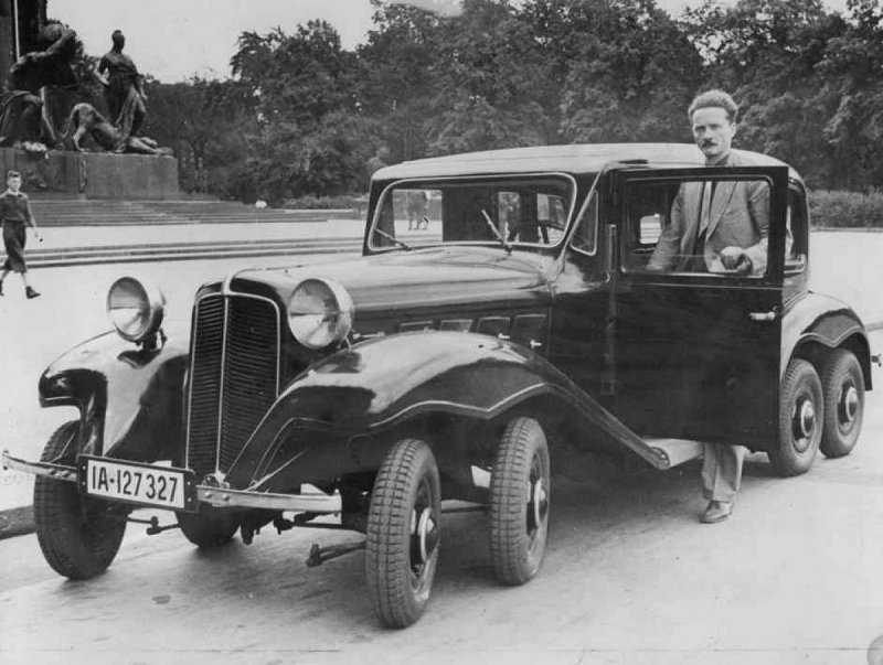 |
| Left: The Rimmek eight-wheeler in Berlin: 1935
In 1935 German engineer Gotthard Rimmek patented his first eight-wheeled model. The first prototype was a converted Brennabor car in 1925.
This was followed by a more sophisticated conversion of a German Adler Diplomat, a big six-cylinder 3-litre saloon introduced in 1934. The conversion boasted 'oscillation parallelograms in a progressive suspension" and when I find what that means I'll let you know.
Those steering arms look a bit flimsy...
|
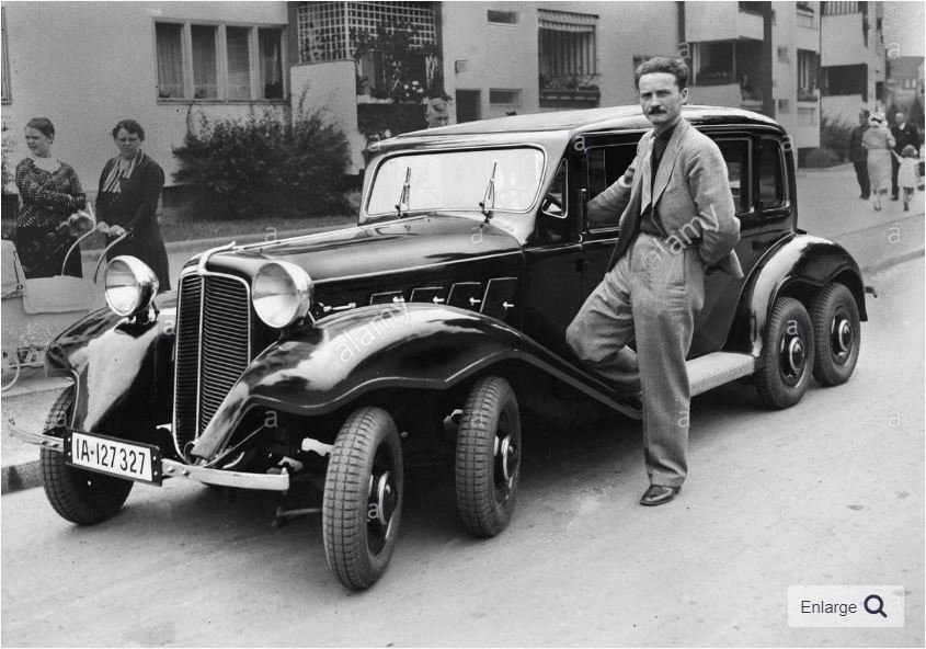 |
| Left: The Rimmek eight-wheeler in Berlin: 1935
Rimmek applied for a German patent in March 1926, and patent DE452836C 'Kraftfahrzeug mit zwei vorn und hinten angeordneten abgefederten Radachsenpaaren' was granted in November 1927. The title just means 'Motor vehicle with two front and rear sprung pairs of wheel axles' which tells us nothing more.
Apart from this no further history of the Rimmek cars has been discovered by the Museum Staff.
|
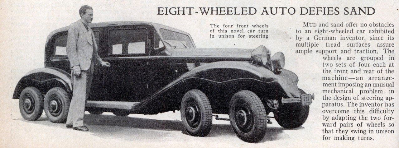 |
| Left: The Rimmek eight-wheeler: Magazine article
This looks as though it came from Popular Mechanics, or a similiar publication.
|
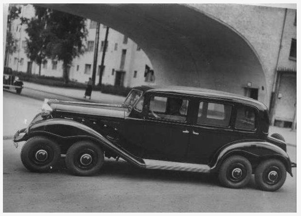 |
| Left: The Rimmek eight-wheeler in Siemensstadt, Berlin: 1935?
The location is the intersection of Goebelstraße and Quellweg in Siemensstadt, in the north-west of Berlin. The area is called Siemensstadt as it was purpose-built housing for the employees of the Siemens electrics works.
As for Goebelstraße it is named after the inventor Heinrich Goebel.
Things have not changed much there; see Google streetview.
For some reason the photograph was taken on the tilt.
This remarkable piece of geographical detective work was done by Bernd F, to whom much thanks
|
 |
| Left: The Rimmek eight-wheeler as reported in an Australian newspaper: 1935
The report claims that "...most road shocks in motoring are caused by rebounds from the bumps as the wheels drop into potholes, these are almost eliminated... as one wheel passes over the pothole, its neighbour is still on level ground, holding the car on its straight, smooth passage."
I appreciate that road-building standards in Australia in 1935 may have been different from what they are now, but I am not wholly convinced this is an accurate description of car suspension dynamics. It does however seem to give some insight into what Rimmek was aiming at.
However this is contradicted by the magazine piece just above, which suggests that improved traction in mud and sand was the aim.
From the Northern Times (Carnarvon, WA) for 18 Sept 1935
|
8 WHEELS: THE T-13 HORNET B TRACKLESS TANK: 1940
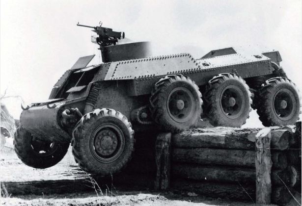 |
| Left: The T-13 Hornet B Trackless Tank: 1940
The T-13 Hornet B was a heavy eight-wheel armored car/tank, developed in the late 30's as a private venture by the Trackless Tank Corporation. The rear six wheels were driven, giving an 8×6 format. The Hornet weighed 7.5 tons with a turret fitted. The prototype (seen here) did not have the turret mounted, just a small machine-gun position.
The Hornet was trialled by the USA, British and Australian armed forces, but only a few were sold.
Many heavy armoured cars had eight wheels. Examples are the German 8-Wheeled Sd.Kfz.232 and the Panhard EBR 75.
There is more information here. There does not appear to be a Wikipedia page.
|
8 WHEELS: THE RAIL TRUCK: 19??
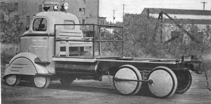 |
| Left: The Rail Truck: 1937
This vehicle is now known to be a railroad inspection car. As far as I can see there are no tyres on the wheels for road use, just flanges for rail operation.
The two rear axles are coupled with a rod exactly as in steam engine practice. The two front axles with the small wheels look rather like a locomotive bogie, but there seems very little room for such a bogie to swivel.
It says "RAIL TRUCK" on the door but no other text is legible. The location is probably the USA, judging by the transformer on a pole in the centre background.
Little is known about the machine; a reverse image search yields no info. If anyone knows anything about this odd machine, I will be very glad to hear it.
|
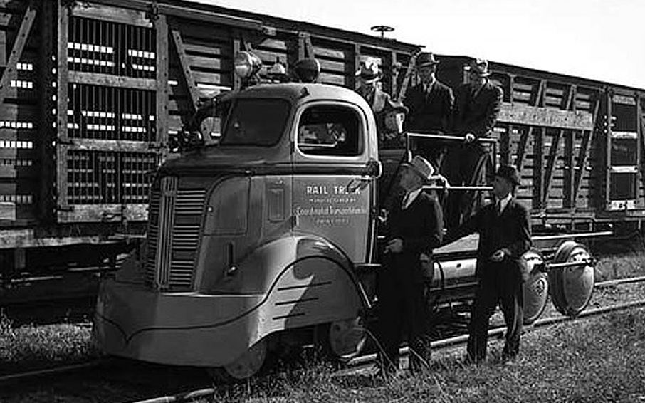 |
| Left: The Rail Truck: 1937
This is another view of the rail truck, and it is confirmed it was built in the USA. It was manufactured by Coordinated Transportation Inc, of Minneapolis, in October 1937. The company is unknown to Google.
|
8 WHEELS: ADVERTISING FANTASY: 1950s
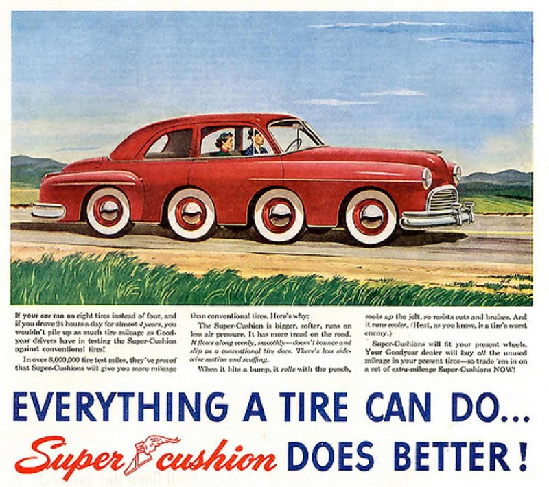 |
| Left: Advert for Goodyear Super Cushion tyres: 1950s?
This wholly imaginary vehicle is designed to emphasise how much testing went into the tyres' development.
I wrote here: 'Despite diligent googling of 'super cushion tyre company' no trace of a 1950's company has been found.' The next day several emails arrived pointing out that Super Cushion was not a tyre company, but a brand of bias-ply tyre sold by Goodyear from the mid-late 1950s to the early 1960s.
However you can buy super cushion tyres today, though interestingly they are solid tyres for earth-moving equipment.
Thanks to Yukisdad for the image, and to all my Super Cushion correspondents.
|
8 WHEELS: THE HOME-BUILT OCTO-ROD: 1961
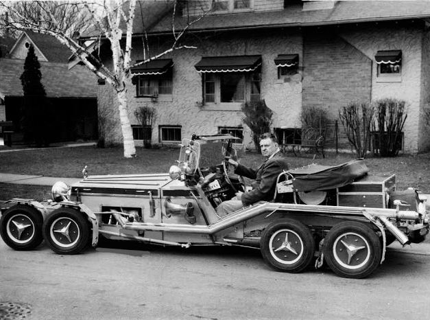 |
| Left: The Octo-rod eight-wheeled car: 1961
This vehicle has been identified by Paul Dunlop as the Octo-rod, built by Enoch Johnson of Red Wing, Minnesota, between 1946 and 1961.
One can only speculate as to why the driver (presumably Mr Johnson) is looking so grim.
The design of the wheels suggest Mercedes parts may have been involved.
Thanks to Paul Dunlop for identifying this vehicle.
|
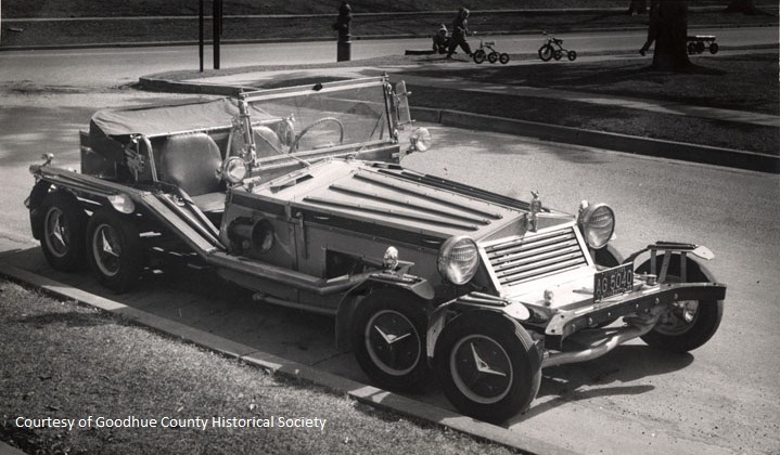 |
| Left: The Octo-rod eight-wheeled car: 1961
The Octo-rod was powered by a 1951 Dodge Red Ram Hemi V8 engine of 5.4 Litres, developing 180 HP. No other mechanical details are known; there's no doubt that all four front wheels steered but it is not known if both rear axles were driven.
|
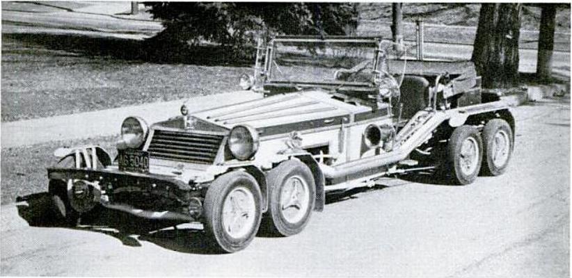 |
| Left: The Octo-rod eight-wheeled car: 1961
The Octo-rod 8-wheel car is today on display at the Pioneer Auto Museum in Murdo, South Dakota.
Many more pictures of the Octo-rod can be see here. The car was featured in Hot Rod magazine at some point.
|
8 WHEELS: THE ELIICA: 2004
The Eliica was and is (the project appears to be in continuous development) electric car developed by Keio University in Japan, first shown in 2004. It uses lithium-ion batteries. It is allegedly faster than a Porsche 911 Turbo. Despite its large size it only seats four people.
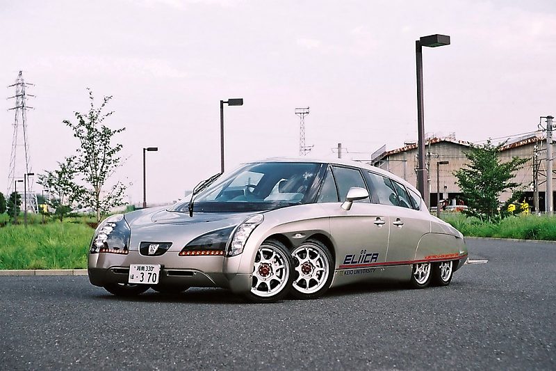 |
| Left: The Eliica: 2004
The Eliica has eight wheels, supposedly to improve traction. They are smaller than normal car wheels, allowing the vehicles to be closer to the ground for better aerodynamics and stability. Each of the eight wheels is driven by a 60 kW (80 hp) electric motor, giving 480 kW (640 hp) eight wheel drive in total, with regenerative braking to recover energy. The four front wheels steer. Each of the eight wheels has a disc brake.
Eight-wheel drive might in theory allow the Eliica to deal with all kinds of road surfaces, but the low ground clearance suggests that off-road operation is not a sensible option. Smooth acceleration of about 0.8 g is claimed.
The Eliica is a development of the earlier KAZ (Keio Advanced Zero-emission vehicle), which was a 6.7 m (22 ft) limousine-sized 8-wheel 8-person electric vehicle prototype announced in 2003.
|
EIGHT-WHEELED TRACTORS
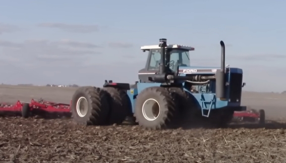 |
| Left: Ford eight-wheeled tractor
If you're dealing with soft soil, one solution is a four-wheel-drive tractor with two tyres on each axle. This is a Ford
|
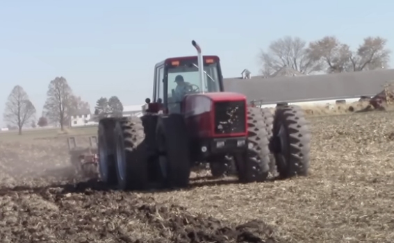 |
| Left: Eight-wheeled tractor by International
Note that the wheels here are spaced about a foot apart, presumably to spread the weight out as much as possible.
|
8 WHEELS: THE OSHKOSH M1070 TRACTOR: 1992
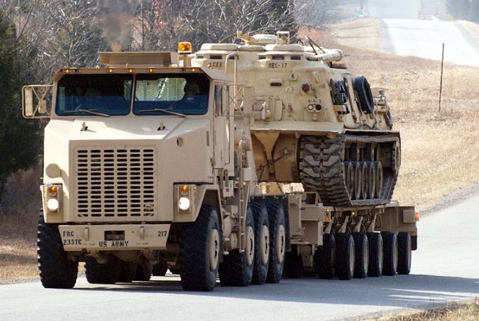 |
| Left: Oshkosh eight-wheeled tractor
This tractor unit is in service with the US and British Armies, usually hauling tank-transporter trailers.
Both front and the rearmost axle are powered and steer. Production commenced in 1992. The M1070 has a Wikipedia page.
|
9 WHEELS
The search for a nine-wheeled vehicle is over.
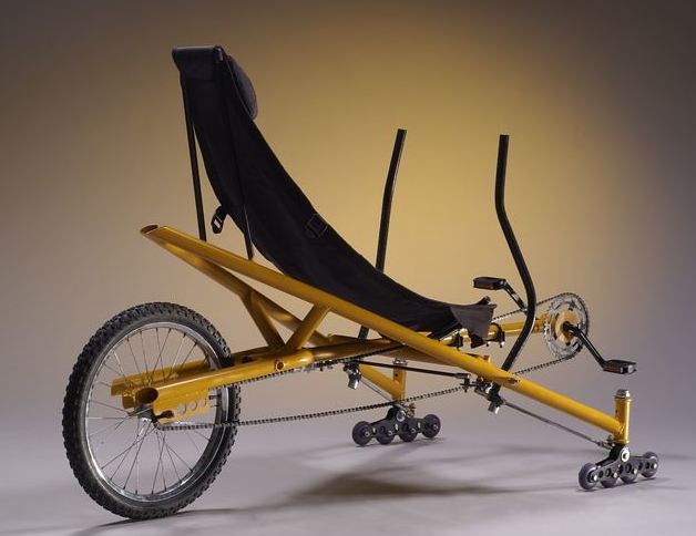 |
| Left: The Nonacycle: 2001
This semi-recumbent 'bicycle' was built by Rick Unger in Autumn 2001, to be auctioned off at a Patchwork Central Holiday Sale in November 2001. However, the reserve price of $500 was not met. The frame was built up from twenty feet of exhaust pipe.
At the front there are four small wheels on each side, plus one normal one at the back, making nine. Steering is by the two levers. It is not practical transport; the tiny wheels will be stopped by the smallest obstruction, and since they appear to have solid tyres, it's going to be a rough ride.
|
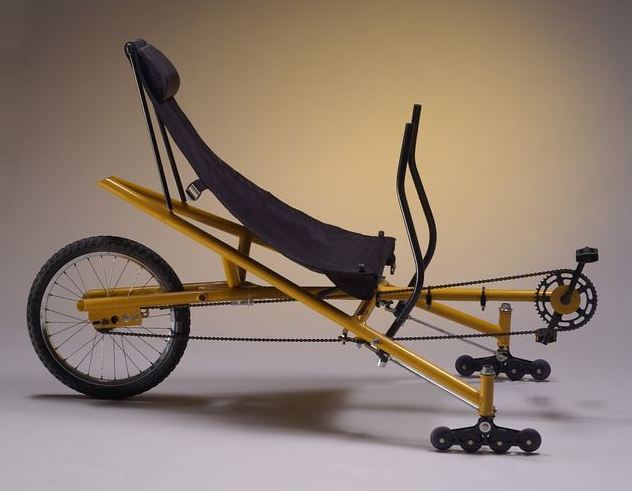 |
| Left: The Nonacycle: 2001
Call me picky, but I don't see any sign of brakes here. Maybe that's why it didn't sell.
No sign of gears either.
|
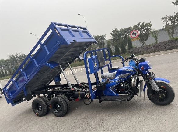 |
| Left: The Benne Cargo Tricycle: 2025
This is the Benne Cargo Tricycle, with one wheel at the front and eight at the back. I think this counts as a nine-wheeler. The cargo section tilts hydraulically.
It has a 350cc engine and is made in China. There is also a five-wheel version with a 250cc engine.
You can see a video of it on AliBaba.
Grateful thanks to Steven McDonald for drawing this vehicle to my attention.
|
10 WHEELS
10 WHEELS: THE MILLES-PATTES
No problem at all. This car- and I submit it is more a car than anything else- was built by Michelin in 1972, when they were major shareholders of the Citroen company. It is officially called the Citroen DS PLR break, where PLR stands for Poids Lourd Rapide meaning heavy fast truck. It was built as a way of safely testing of truck tyres at speed on a real road. Unofficially it is known as the mille pattes or 'thousand paws', which is the French word for centipede, not, as you might expect, millipede. I feel obliged to point out that no millipede has as many as 1000 feet; the record is up to 750, for Illacme plenipes.
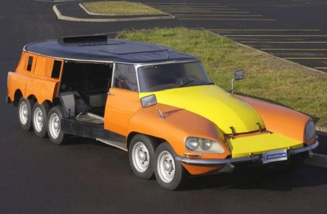 |
| Left: The mille pattes tyre-testing car: 1972
The mille pattes has four wheels at the front, and six wheels at the back. Why so many? Because the vehicle was loaded down with lead until it weighed 9.5 tons; this was so that realistic truck loadings could be placed on the tyre under test. A strong metal casing retained tyre fragments if it disintegrated, and the ten other wheels allowed control to be maintained if that happened. In fact it was only ever used on a closed test circuit.
The car used as many standard parts as possible, and so bears a distinct resemblance to a Citroen DS. The tyre to be tested was installed in the centre of the car, shown open in this picture.
It is powered by two 454 Big-Block Chevrolet engines, one of which drove the rear six wheels, and the other the tyre under test. Top speed is over 110 mph.
The mille pattes has a Wikipedia page.
|
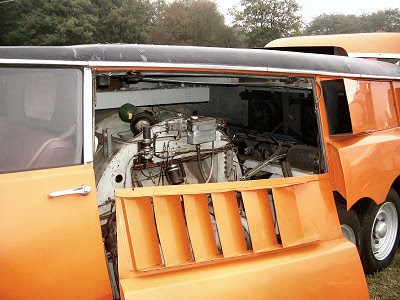 |
| Left: The mille pattes tyre-testing car: 1972
Here one of the side-panels has been removed, showing the enclosure for the tyre under test.
You can learn more about this wonderful vehicle here.
There is a video on YouTube.
Die cast models were made in 1972 and sometimes surface on Ebay.
|
The mille pattes is no longer used for tyre testing but remains in use as a promotional vehicle. It spends most of its time at the Michelin Museum in Clermont-Ferrand.
Many thanks to Sean O'Brien for bringing this remarkable machine to my attention.
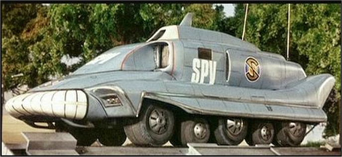 |
| Left: The Spectrum Pursuit Vehicle: 1967
The Spectrum Pursuit Vehicle (SPV) is a fictional 10-wheeled attack and pursuit vehicle that featured prominently in Gerry and Sylvia Anderson's science-fiction television series Captain Scarlet and the Mysterons. (1967) Only the first, third and fifth axles were powered, and these carried larger wheels. The maximum speed was a rather unlikely 200 or 250 mph, depending on episode. A notable feature was that the crew of two faced backwards (for better crash protection) and drove using a television screen and front-mounted camera; this was an awkward decision as it had to be explained several times in the series.
The SPV was usually manned by Captain Blue and Captain Scarlet; Captain Blue was a skilled SPV driver, but Captain Scarlet crashed several times. Fortunately he was Indestructable.
The SPV has a Wikipedia page.
|
10 WHEELS: THE 45-FOOT CADILLAC LIMOUSINE
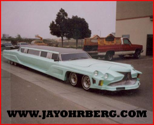 |
| Left: 10-wheeled 'Cadillac'. Date unknown
Built by Jay Ohrberg. (see below) Unfortunately no technical details are currently available.
|
10 WHEELS: THE FERRARI F40
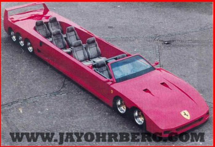 |
| Left: 10-wheeled 'Ferrari'. Date unknown
Four wheels at the front and six at the back.
Built by Jay Ohrberg. (see below) Unfortunately no technical details are currently available.
|
11 WHEELS: THE MILLES-PATTES AGAIN
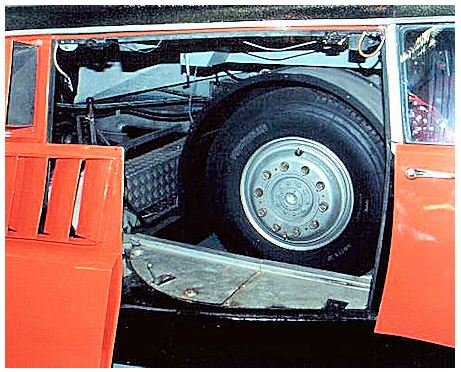 |
| Left: Truck tyre installed in the mille pattes for testing: 197?
Well, I'm quite sure you saw this coming. The milles-pattes car has eleven wheels on the road when a truck tyre is installed for testing. In the YouTube video a test tyre is fitted.
|
12 WHEELS: THE DESERT RENAULT MH
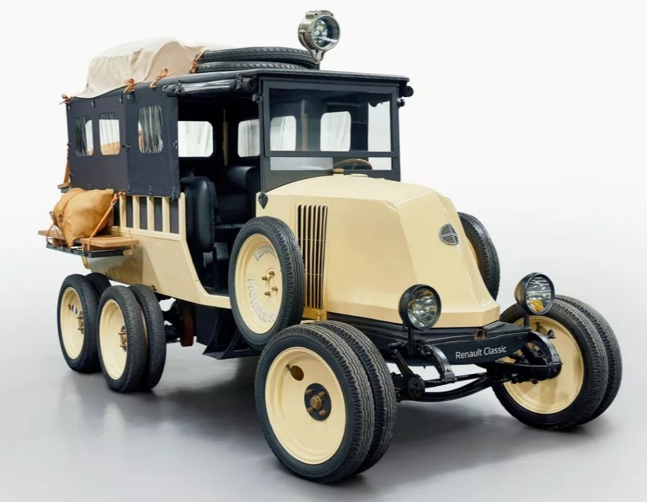 |
| Left: The desert Renault MH car: 1923
The Renault MH was designed to cope with desert conditions, having three axles, each carrying four wheels, to give low ground pressure. It also had a large ground clearance. Only the rear two axles were driven. Note a spare wheel either side of the bonnet, and two more spare tyres on the roof. Renault were doing things throughly.
I think this is indisputably a 12-wheeled vehicle. It was a response to Citroen, who in 1922 sent out tracked vehicles to cross the Sahara. At the time there were no railways joining north and southern Africa.
If you're wondering about the forward-facing louvres on the bonnet sides, they are to let air into the radiator, which in Renault cars of this era were behind the engine.
At the end of 1923, the first mission was accomplished—an overland drive from Touggourt in Algeria to Tozeur in Tunisia in two days. In January 1924 the Gradis-Estienne expedition linked Algeria to Niger.
|
12 WHEELS: THE AUSTRIAN ADGZ
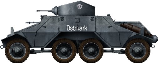 |
| Left: The Austrian ADGZ armoured car: 1934
The ADGZ was a heavy armoured car developed by the Austrian firm of Steyr. It was intended for 'internal security duties' which no doubt covered a multitude of sins. A total of 27 were built between 1935 and 1937; after the 1938 Anschluss they were taken over by the Germans.
This vehicle caught the attention of the Museum Staff because of the unusual configuration with the two middle axles close together. Investigation showed that in fact it had not eight wheels, as it first appeared, but twelve, as the two middle axles each carried four wheels. I'm certainly prepared to accept this as a twelve-wheeled car.
Another interesting feature of the ADGZ, which it shared with the Swedish FM29 armoured car of 1932, was that it was designed with rapid retreat in mind. The body was essentially symmetric with a driver, headlights, and an M34 machine gun at each end, with a dual transmission so that the drivers could rapidly switch roles. The engine was at the rear. The turret carried a 20mm KwK 35 L/45 autocannon.
|
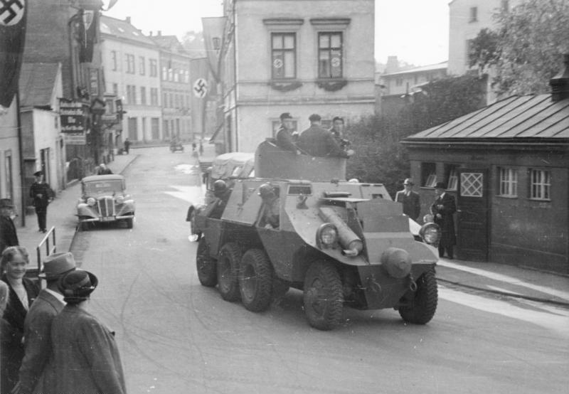 |
| Left: An ADGZ armoured car in the Sudetenland: 1938
Here it is just possible to make out the second wheel on one of the middle axles. The turret had a double hatch on top, which could be fully opened, as shown here.
The Sudetenland was the northern, southern, and western areas of what was then Czechoslovakia. It was annexed by Germany in 1938
|
12 WHEELS: THE MAZ-547 MISSILE TRANSPORTER
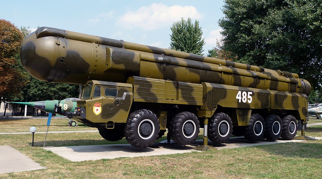 |
| Left: 12-wheeled Russian missile transporter: 2009
The MAZ-547 transporter is a six-axle version of the MAZ-7310 8x8 artillery tractor, designed to carry the RSD-10 Pioneer medium-range missile.
|
14 WHEELS: MULTI-RIDER DELIVERY BIKE
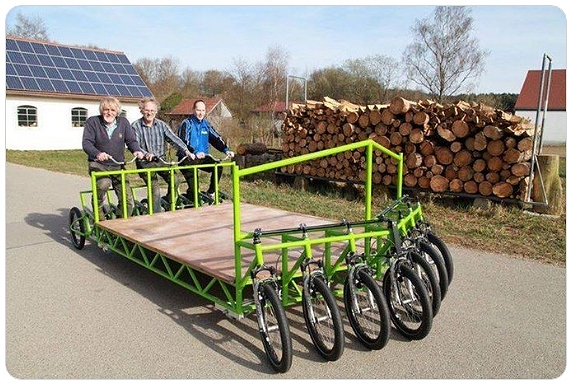 |
| Left: 14-wheeled delivery bike: date unknown
As far as I can tell there are seven wheels at the back as well, but it's not very clear. Nothing known at present. And yes, it is stretching the definition of a car.
Google reverse image search yields nothing.
|
16 WHEELS: RUSSIAN MISSILE TRANSPORTER
 |
| Left: Russian 16-wheel missile transporter: Moscow Parade rehearsal 2012
It has only just occurred to me that missile transporters have a lot of wheels. This is a Russian MZKT-79221 transporter. It is powered by a 800HP V12 diesel engine.
It carries a RT-2PM2 Topol-M ICBM.
|
18 WHEELS: THE 72-FOOT CADILLAC LIMOUSINE
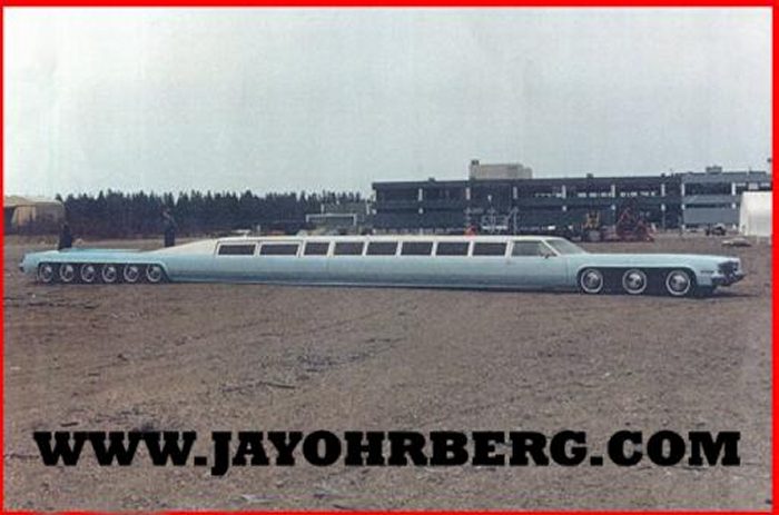 |
| Left: Jay Ohrberg 18-wheel Cadillac: date unknown
Here we have six front wheels, and twelve rear wheels, for a meritorious total of eighteen. You may be wondering why twelve wheels are required to support the rear of the car; it's because that's where the swimming pool is.
Built by Jay Ohrberg. (see below) Unfortunately no technical details are currently available.
|
24 WHEELS: THE AMERICAN DREAM LIMOUSINE
Jay Ohrberg of Burbank, California, is an American constructor of special cars, including several Batmobiles and KITT from Knight Rider. This 100-foot vehicle is accepted by the Guinness book of Records as the world's longest car.
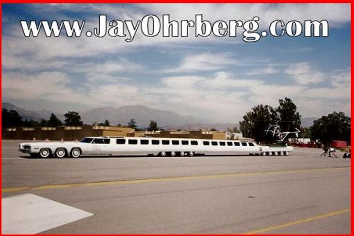 |
| Left: The American Dream 24-wheel car: 1986
Here we have six front wheels, eight middle wheels, and ten rear wheels, for a grand total of 24 wheels.
This is not photoshopping. Many more pictures of the American Dream can be seen at Jay Ohrberg's website. There is a helipad at the rear of the limo, over the rear wheels, with a helicopter sitting on it.
The car deteriorated in storage for some time.
Jay Ohrberg has a Wikipedia page.
I asked Mr Ohrberg by email for permission to post a pic or two, but have had no answer so far.
|
26 WHEELS: THE AMERICAN DREAM LIMOUSINE
I am glad to report that the American Dream has been fully restored. An article in topspeed.com says several times that wheels have been added to make a total of 26, buy this cannot be seen in contemporary photographs.
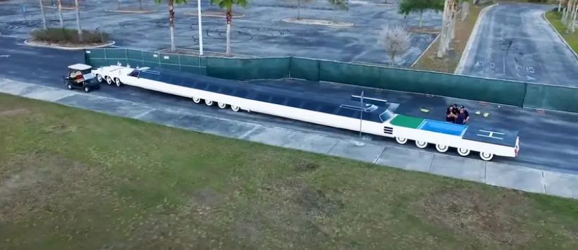 |
| Left: The American Dream 24-wheel car: 1986
Here we still seem to have six front wheels, eight middle wheels, and ten rear wheels, for total of 24 wheels. There are only three axles at the front, there is not another wheel hidden behind the golf cart. Perhaps the answer is that one axle now has 4 wheels on it.
The car is now officially the longest car in the world. At the right (rear) can be seen the helipad, the swimming pool, and the miniature golf course.
|
30 WHEELS: COZAD TRACTOR & TRAILER
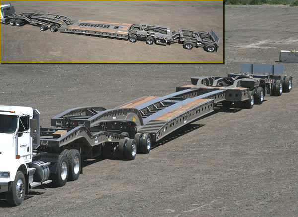 |
| Left: Cozad 9-axle-stretch-deck-booster-trailer: 2022
This tractor-trailer combination is designed to move big loads weighing up to 80-85 tons. There are two single wheels at the front of the tractor and two axles carrying a total of 8 wheels at the rear. The trailer has six axles, each carrying four wheels; on each side there are two wheels outside the chassis side-member and two inside. That adds up to 30 wheels
There are more pictures and technical drawings at the Cozad website.
|
40 WHEELS: M1000 TRAILER
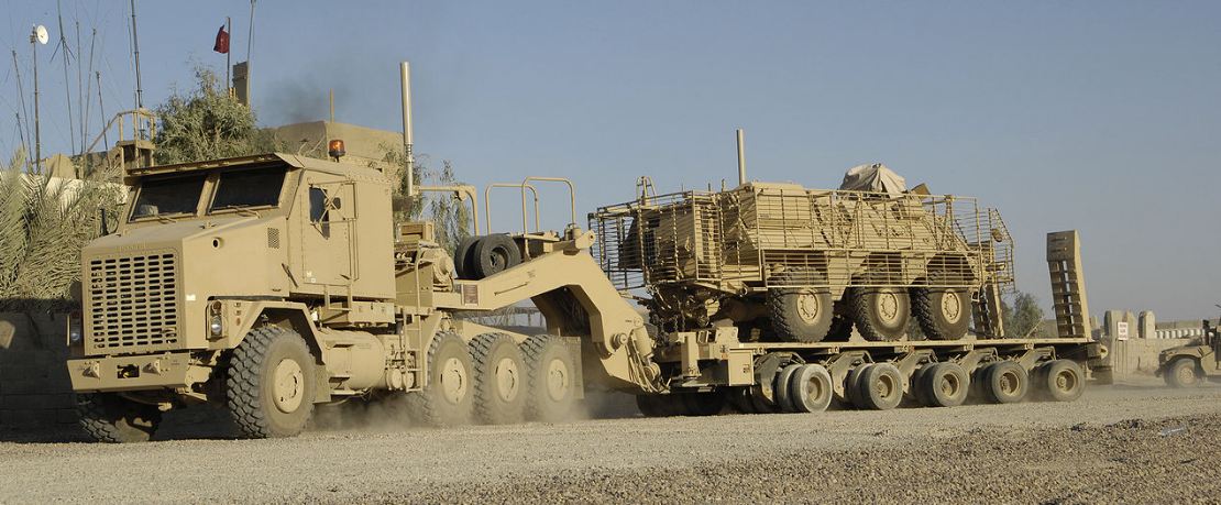 |
| Left: M1000 trailer: 2022
The M1000 has 40 wheels (215/75R 17.5 tires) on five axles, with four wheels on each side of of each axle. Each axle has hydraulic suspension providing a 254 mm travel. The M1000 is weighs 22,882 kg. Payload according to the US Army is 63,560 kg, though the manufacturer quotes 80,000 kg at reduced speeds.
|
The overall length is 15.8 m, deck length 10.58 m; deck width 3.05 m, or 3.66 m for a wide deck version.
The M1000 is hauled by the M1070 8-wheel tractor
72 WHEELS MINIMUM: THREE TRACTORS & A TRAILER
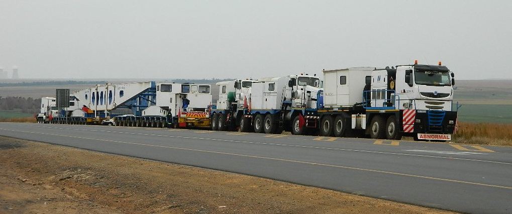 |
| Left: Rotran Set headed by a Nicolas Tractomas Truck: South Africa 2015
This Abnormal Vehicle is a Rotran Set headed by a Nicolas Tractomas Truck, and two International Pacific tractors [Ex South African Railways] with a Girder Beam carried on two Multi Axle Nicolas Trailers.
|
If I've counted correctly, 38 wheels are visible in the picture, on one side. So there must be at least 76 wheels when we include those on the other side. However most of the wheels will be at least double and may very well be fourfold as in the 30-wheeler shown above. If we assume all wheels are double (and none fourfold) except for the single steering wheels on the two International Pacific tractors, we get a total of 76 - 4 = 72 wheels. Impressive.
Now all we have to do is decide if this train counts a 'one vehicle'.
This may not be the limit; there may be bigger trailers out there.
76 WHEELS DEFINITELY: THE ORBITER TRANSPORTER SYSTEM
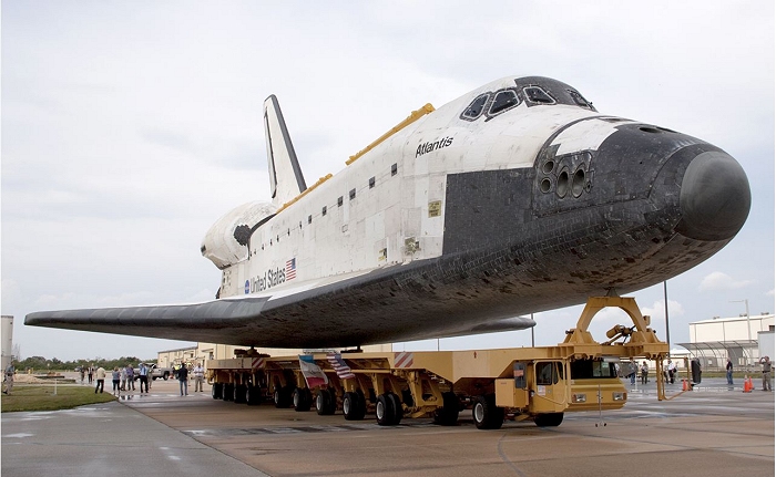 |
| Left: The Orbiter Transport System (OTS) moving Space Shuttle Atlantis to a museum: 2012
The Orbiter Transporter System was originally used by NASA to move the Space Shuttle Orbiters around Cape Canaveral. It was made by the Italian firm of Cometto in Italy; they specialise in multi-wheel vehicles for very heavy loads. It was used at Vandenberg AFB (Now Vandenberg Space Force Base) to transport the orbiter from the Orbiter Maintenance and Checkout Facility (OMCF) on North Vandenberg to the launch pad (SLC-6) on South Vandenberg. This was a 16.5 mile (26.5 km) long trip over hilly terrain.
The OTS had a maximum speed o5 5 mph when carrying a shuttle.
OK, let's count wheels. There are 4 at the front, and behind that 9 axles are visible, each carrying 4 wheels; there are another 9 axles on the other side, so 4 + (2 x 36) = 76 wheels. Impressive!
Grateful thanks to Jerry Carlett for drawing this vehicle to my attention.
|
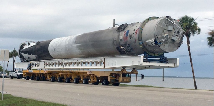 |
| Left: The Orbiter Transport System (OTS) moving a recovered Falcon 9 booster: 2016
In 2011 the OTS was retired with the end of the Space Shuttle Program, and was sold to Space-X in a government surplus auction in 2014 for a mere $37,075. It was modified to carry the longer but lighter Falcon 9 booster, and has been back in service since 2016 moving recovered boosters between facilities.
I wonder what the steering is like. I imagine some of those rear axles must steer.
|
1496 WHEELS: HOW TO MOVE A SHIP ON LAND
 |
| Left: Moving a 20,000 ton ship on multiple modular transporters: 2022
Mammoet, the heavy-lift company, ganged together enough self-propelled modular transporters (SPMTs) to move a 20,000 ton ship on land. Each SMPT has 8 independently powered and steered axles, with two wheels on each. As many modules as necessary can be bolted together to make a huge moving platform. They are all networked to coordinate steering and speed. You can see it in action here.
The SMPTs are almost hidden by the hull, but you can see some of the 1496 wheels under the ship. The figures of two workers left of centre give an idea of the scale of this operation.
According to Mammoet: "A record-breaking 748 axle lines of SPMT and 30 power packs have been used – making this project a double world-first for both the largest number of axle lines and the heaviest weight carried by SPMT." Hmmm. 748 divided by 8 = 93.5 SMPTs. Something not quite right there, but 748 axles carrying two wheels each gives an impressive count of 1496 wheels.
There is more information on the the Mammoet Self-Propelled Modular Transporter (SPMT) here.
Grateful thanks to Francis Herne for drawing this to my attention.
|
This looks like a record that going to stand for a while. But does it count as a vehicle? I think I can say without fear of successful contradiction it does.


