In 1912 the Russian Count Peter P Schilovski, a lawyer and member of the Russian royal family, visited the Wolseley Tool and Motorcar Company, and laid before their engineers plans for a two-wheeled gyroscopically-stabilised car. At that time Wolseley were a sizable manufacturer producing ordinary cars, double-decker buses, taxicabs, lorries and even powerboat engines.
The Wolseley men were clearly impressed, as the job was accepted, and work began immediately, under the supervision of A W Dring, the Chief Experimental Engineer. The chassis took a year to build, which seems impressively fast given the amount of experimentation that must have been needed. The Count was a frequent visitor during this period to the Adderley Park works in Birmingham.
Some milestones in the development of the "G Y car" as it was known within Wolseley can be deduced from company reports:
9th October 1912 Testing suspension springs
21st October 1912 Engine testing
14 July 1913 Chassis complete
November 1913 Car complete
| | | | | | | |
The Count claimed that his vehicle would be of great military value; it would be able to cross terrain that would defeat 4-wheeled vehicles, and it would require less power to reach a given speed. It has to be said that neither claim seems very convincing.
At this time motor vehicles were still in their infancy, and the application of the internal combustion engine to military transport had barely begun. The Russian Army was the least technically advanced in Europe, and starting its mechanisation with such an unusual and probably delicate vehicle does not sound like a very good idea...
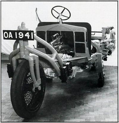
Above: The Gyrocar before the bodywork was fitted; photograph taken shortly before the first test run. The pendulum weights are hidden by the chassis members. That looks like the Count on the left.
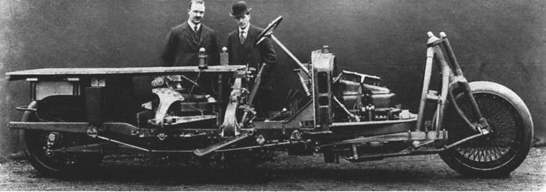
The Gyrocar was powered by a modified Wolseley C5 engine of 16 - 20 hp, with a bore of 90mm and a stroke of 121mm. It was mounted ahead of the radiator, driving the rear wheel through a conventional clutch and gear box. A transmission brake was fitted after the gearbox- there appear to have been no brakes on the wheels themselves. The small size of the engine in the photograph (in an era when specific outputs were low) indicates that the Gyrocar was distinctly underpowered. The weight of the vehicle was 2.75 tons, concentrated on two wheels- not promising for the heavy mud of the Eastern Front. It has also been said that it suffered from a very large turning circle- again not a good thing in a proposed military vehicle.
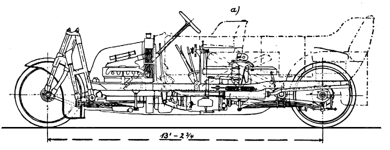
Above: Side elevation of the Gyrocar. The gyroscope is in the centre, with its possible angles of fore-aft tilt shown.
<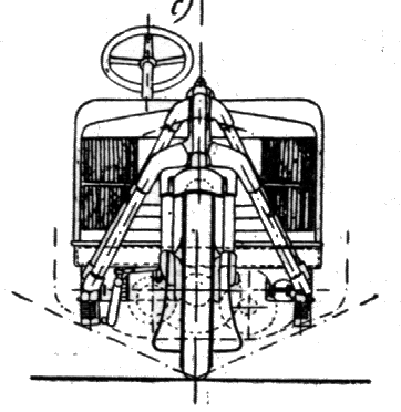 |
| Left: Front elevation of the Gyrocar
Showing the permissible angles of tilt of the car.
Note radiator mounted behind the engine and divided into two sections.
These three drawings are taken from Schilovski's book.
|
 |
| Left: Plan of the Gyrocar.
Note the large amount of space taken up by the gyroscope, and the offset driveshaft to the rear wheel. The seats are not visible on this drawing.
|
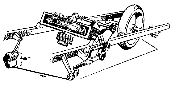
The gyroscope was of 40 inch diameter and 4.5 inch thick at the rim, and spun at between 2000 and 3000 rpm, powered by a 110V 1.25 hp electric motor. This was beneath the gyro on the same spindle for direct drive. The motor was powered from an engine-driven dynamo mounted beside the clutch. The gyro rotor weighed 12 cwt and apparently absorbed 10% of the engine power. A centrifugal governor rang an alarm bell if gyro rpm fell too low, and support sprag wheels on either side were automatically lowered to prevent the car falling over. A rather fragile-looking system of toothed quadrants actuated by two 95 lb pendulums maintained stabilisation; more details below.
Patents were taken out for the Gyrocar:
British Patent No 12,021 (1909)
British Patent No 12,940 (1914)
New provisional specifications in 1923
 |
|
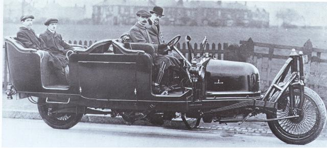
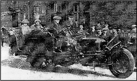
Going for a spin in the Gyrocar.
Another picture of the same outing, sadly of poor quality.
|
This report comes from A W Dring:
"On November 27th, 1913, I made an effort to move the car, which was successful, no derangement of the governing gear taking place. We drove the car backwards and forwards for a distance of about six feet many times. During these tests it was noticeable that one could stand on the side of the car and step into the body without any disturbance of balance. We then moved the car partially round a radius to the left, backwards and forwards. Eventually we drove the car the whole length of the works, backwards and forwards, with four passengers.
Then His Excellency decided to take the machine over on to the track, impressing me that we must go very gently. We drove onto the Arden Road, making two stops on the curve, and we had to reverse so that we should not use full lock. I then drove the car steadily up the Arden Road, going as slowly as possible and slipping the clutch in first gear all the time. We took a wide sweep into the Bordesley Green Road, and suddenly, when opposite the Directors' mess room, the vehicle heeled to the near side and dropped on its sprag. It was lifted by eight men, the engine restarted, and the car driven back to the experimental department, but it was supported by outside assistance as His Excellency did not attempt to balance the car in the street."
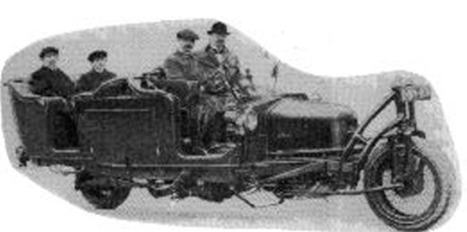
On April 28, 1914, the first public demonstration took place before a large and interested crowd in Regent's Park, in central London. According to a contemporary newspaper report, could crawl along with people jumping on and off, and still maintain its stability.
 |
|
Another picture of the machine out and about, unfortunately also of poor quality.
This is clearly a different run- note the two ladies in the back. Once more the car appears to be balancing while stationary.
|
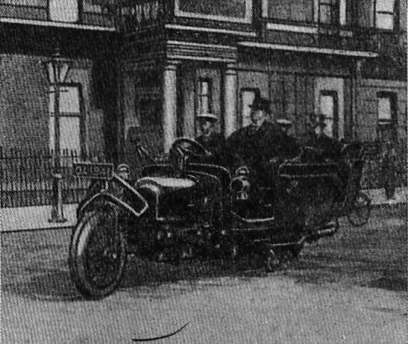 |
| The gyrocar on the streets of London
Date: May/June 1914
On the original photograph the numberplate can be seen to read "OA1941".
|
BURIAL
At the outbreak of the First World War in 1914, The Count returned to Russia. Wolseley were fully occupied in war work, and the Gyrocar was not uppermost in their minds; it lay abandoned in a corner of the factory.
The Wolseley directors not unaturally assumed that the Count had been a casualty of either the war or the Russian Revolution. Wanting to get it out of the way, but not wishing to dispose of it completely, they hit upon the extraordinary solution of burying it. This is not normally considered an appropriate method for the long-term storage of motor vehicles.
EXHUMATION
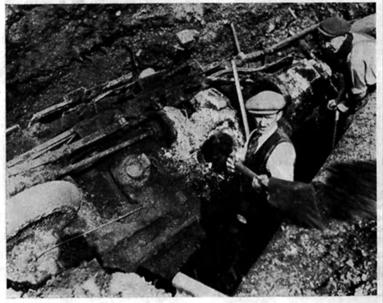 |
| Left: Digging the Dirt
In 1938 it was decided to exhume the Gyrocar. It looks as though it was interred upside down. The wheel to the left appears to be the rear one; the rod just above it is probably the propellor shaft. (driveshaft)
Note that in 1938 hole-digging appears to be a waistcoat-and-tie job.
|
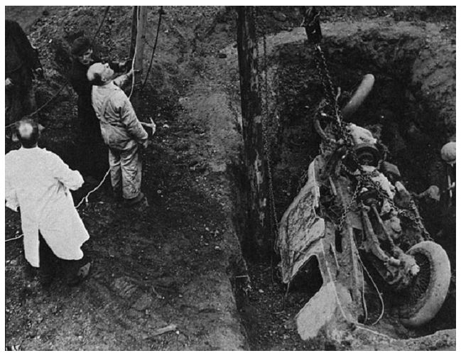 |
| Left: Getting the Gyrocar ready to lift
This confirms that the Gyrocar was buried upside down. Presumably they dug a pit, wheeled the Gyrocar up to the side of it, and tipped it in. What were they thinking of?
Remarkably, it looks as though there is still air in both tyres.
|
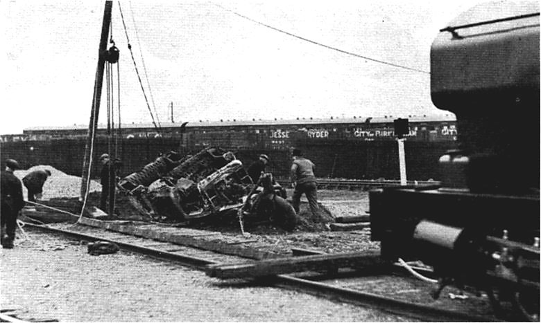 |
| Left: The gyrocar emerges
At this point the gyrocar has been turned right-way-up.
Exhumation was not made easier by the fact that a railway yard had been built on top of the burial site. However, the tracks were lifted, and the car unearthed. It was restored at considerable expense and put on display in the company museum.
|
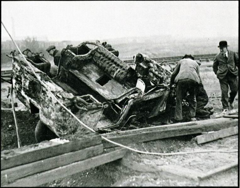 |
| Left: Back on the surface
Seen from the rear of the gyrocar.
The chap in the suit and bowler is no doubt the foreman.
|
 |
| 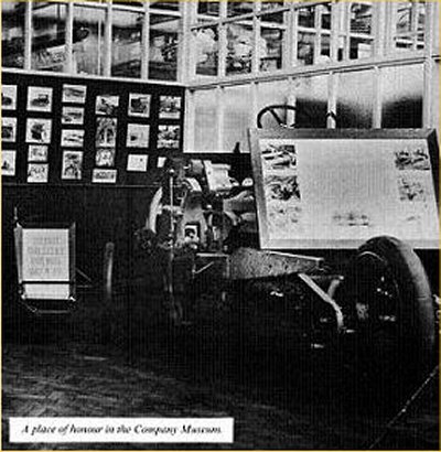 |
| The gyrocar in the Wolseley Museum: 1946?
The bodywork has been removed.
Far left: The front of the Gyrocar.
No doubt about the numberplate now.
Left: the Gyrocar seen from the rear.
I would like to be able to read the placard propped up on the rear chassis.
"A place of honur in the Company Museum" it says. But not for long.
|
However, in what can only be described as a act of bestial philistinism, the car was broken up for scrap in 1948.

CODA: I am glad to report that Count Schilovski did survive the First World War, the Revolution, and the civil war that followed. He returned to England, probably in 1922, living in Dulwich with his wife and three daughters, and working for the Sperry Gyroscope Company.
He (as plain "Mr Shilovsky") wrote an article in "The Morris Owner" for May 1939, advocating gyrocars, especially for colonial use. He accepted that the original prototype had been far too heavy.
I am indebted to Mr George Chkiantz, grandson of the Count, for the above biographical details.
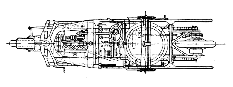
THE MECHANISM.
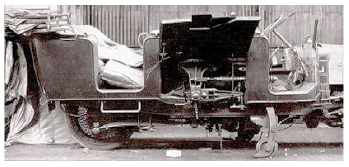 |
| Left: The gyroscope compartment with its door open
The car is here standing on its sprag wheels.
|
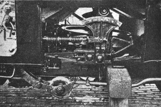 |
| Left: The gyroscope compartment, showing the toothed quadrant on one side. Bottom centre is one of the retracted sprag wheels. The car is propped up on timbers.
Gyroscopic stabilisation sounds easy. You fix a gyro to the chassis (axis vertical so you can go round corners) and the gyro refuses to tip over. Simple, yes?
No. It's not that straightforward. If you have a spinning gyroscope and you try to rotate its spin axis, the gyroscope will instead try to rotate about an axis at right angles to your force axis; this is precession. So when the gyrocar tilts sideways, the precession torque generated tilts the gyroscope in a fore-and-aft direction- not much use. Hence the need for a mechanism to indirectly create a sideways restoring force.
|
 |
| Left: The operation principles of the gyro
If I have understood correctly, it works like this. Any tilting displaces the weights. Through a lever system, the appropriate quadrant is raised until it engages with the gears driven by the cross-shaft running across the top of the gyro. This shaft is driven continuously by a worm on the gyro spindle, so when a quadrant engages the gyro is tilted forwards or back. This, by precession, creates a sideways torque that corrects the tilt.
|
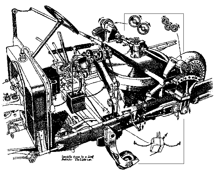 |
| Left: Diagram from "The Light Car", Dec 23, 1938.
The original caption of the above diagram read: "SIMPLICITY was evidently not the watchword of the inventor of the Gyrocar, as this magnificent drawing of the stabilising mechanism shows. The gyro flywheel in its trunnion mounting is on the right between the two toothed quadrants, and the chain and weight controls are in the centre. Inset are (top, right) the gearing between the gyro cross-shaft and the quadrant pinions, and (bottom, right) a detail view of one of the weights."
Given the date, the article was probably prompted by the exhumation of the Gyrocar in 1938. The editor probably wanted something unusual for the Chrstmas number.
Here is Schilovski's own account of how his car performed, taken from his book:
"The car made experimental runs in London in the summer of 1914. But as the eccentricity of the gyroscope was only sufficient for a smooth curve in the direction of spin of the gyroscope, no rounding of sharp curves was possible to the left. This was the only, but very objectionable, defect, and it prevented the development of the system; no remedy was found at that time to enable the car to negotiate sharp curves, either to left or to right with equal ease."
This account tells us that the Gyrocar was basically unworkable without a major redesign of its stabilising system, which is a fact that had not emerged in any of my previous researchs. The meaning of "the eccentricity of the gyroscope" is, I must admit, currently unclear to me. Obviously the actual rotor was not significantly eccentric on its axis or it could never have been spun up to 2000 rpm without destructive vibration.
|
MORE INFORMATION ON P P SCHILOVSKY
The initials stand for Piotr Piotrovich, ie Peter, son of Peter.
Schilovsky did not exhaust his inventive powers with the gyrocar. He appears to have devoted much of his life to developing gyroscope applications:
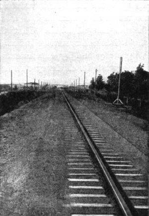 |
| Left: The monorail track between Petrograd and Tzarskoe Selo.
A good deal of Schilovsky's book is devoted to gyroscopically stabilised monorails, and he appears to have worked with the Soviet government, which was experimenting with a monorail link between Petrograd and Tzarskoe Selo in 1921-22.
Petrograd is now called St Petersburg again. Tsarskoe Selo (Royal Village) is now called Pushkin, and is a town 25 km to the south, founded in the 18th century as the summer residence of the tsars.
It seems extraordinary that such an ambitious plan should have been undertaken in a country struggling to recover from revolution, coup, and civil war, but there is the picture to prove it, taken from Schilovsky's book.
About 7 miles of track were laid, but the project was abandoned, due to technical problems and lack of money. It was presumably after this that Schilovsky left Russia for good, and one feels that he was lucky to be allowed to do so.
|
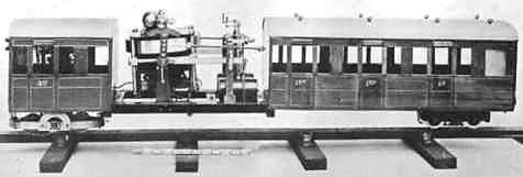 |
| Left: A model of the projected Schilovsky monorail.
Note that there are two wheels at each end, rather like the Brennan monorail.
The scale just below the mechanism has 12 graduations, suggesting it is a foot ruler. This gives the model a plausible size of about 4 feet long. On the other hand, some obscure Russian unit of length might be involved.
|
Schilovsky appears to have co-invented the "Schilovsky-Cooke turn indicator" which was an aircraft instrument, almost certainly based on a gyroscope.
See http://www.warwickaero.co.uk/manualindex/ap1275.html (external link)
He corresponded with Liddell Hart in 1947 on the "invention of a magnetic compass for tanks". I suspect that a gyroscopic compass is what was meant here, which would overcome the problems caused by the large ferromagnetic mass of tanks.
See http://www.kcl.ac.uk/lhcma/cats/liddell/li02st.htm (external link)
There are "various memoirs of P P Schilovsky" in the archives at University College in London.
See http://www.ssees.ac.uk/archives/gle/gle11.htm (external link)