A cyclogyro (or cyclogyre) is an aeroplane propelled and given lift by horizontal assemblies of rotating wings that are caused to change in angle as they rotate. Very few prototypes were built, and those that were constructed were completely unsuccessful. Models have been flown recently.
The assembly of rotating wings is sometimes called a cyclorotor; there is a very good article in Wikipedia.
GABRIEL BABILLOT'S PATENT: 1909
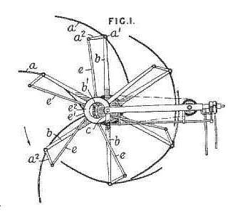 |
| Left: Figure 1 from the Babillot patent: 1909
The patent referred to by Mr Fleischburger below is "Improvements In And Relating To Propellors" British patent No 27,771, 21 Dec 1909, granted to Gabriel Babillot. (there seems to be some confusion about the year; the British Patent Office says 1909)
The wings are shown as thin scoops rather than aerofoils of significant thickness. This matches early aerofoils on conventional aeroplanes, that were also thin and highly cambered. This is because such shapes are more effective than thicker ones at the very low Reynold numbers where the initial studies we done. As engine power and hence speed increased, aerofoils became thicker. Here is an excellent reference from Stanford on the history of aerofoils.
Babillot also took out two French patents that appear relevant; "Propulseur et appareils en comportant application" (FR12136) and "Perfectionnements apportés aux propulseurs ŕ double effet du genre 'hélice'" (FR412306) Details of these are not currently available. That seems to all the information available on Gabriel Babillot, though his patent is referenced in the USAAVLABS Technical Report referenced at the bottom of this page.
|
From the patent text:
...comprises improvements in that type of propeller for marine and aerial propulsion in which the blades are feathered by means of an eccentric mounted on the shaft. The improvements are stated to be applicable to pumps. The vanes a are mounted on axles a' carried on arms b formed integral with the boss b<1> mounted on a shaft c, which may be rotated by the chain-gearing shown. The vanes a may be partly rotated about the axes of the shafts a' by the connecting-rods e secured to levers a<2> and to the eccentric strap e<1> of the eccentric e<2> mounted loosely on the shaft c."
"The rotation of the shaft c and the arms b causes the blades a to oscillate during each revolution in such a way that there are always some in an operative position, the remainder being more or less inactive. The eccentric e<2> may be angularly displaced so that the direction of the thrust may be varied. In a modi. fication, the inner ends of the blades a are made flexible and are united to the hub. The levers a' may also be fitted at each end of the axles a<1> and be connected to separate eccentrics which may be independently operated. This arrangement enables the operator to give a certain amount of twist to the blades."
THE PADDLE-WHEEL PROPELLED BICYCLE
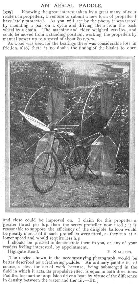 |
| Left: The Paddlewheel Bicycle: 1910
By 1910 the design of aeroplanes had to a large extent settled down into monoplanes and biplanes, powered by either pusher or tractor screw propellors.
But not every-one was convinced. This experimental design had feathering paddles that turned so as to present the maximum area to the air when moving downwards or backwards, hopefully giving both lift and forward propulsion. The text claims the design has been "lately protected" which presumably means a patent had been applied for.
Letter published in the English journal "Flight", 22nd Jan 1910, page 66.
This machine was previously exhibited in the "Odd Bicycles" gallery of the Museum.
|
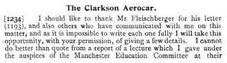
THE CLARKSON AERIAL PADDLE
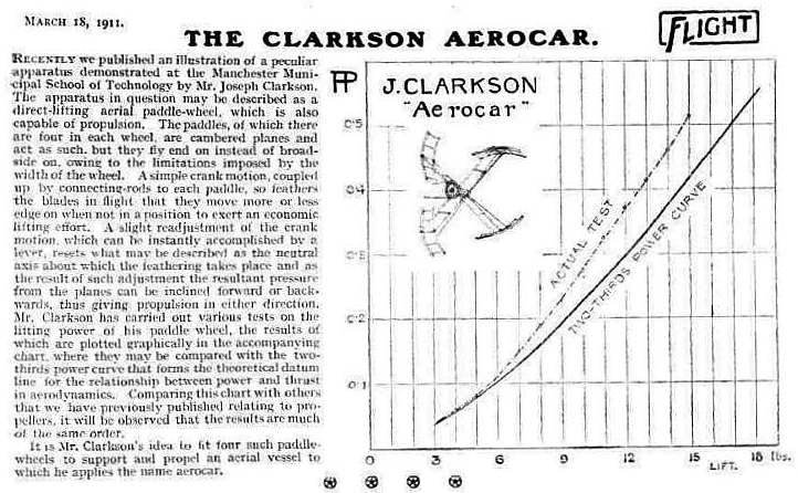 |
| Left: Article in Flight on Joseph Clarkson's aerial paddle
As in the Babillot patent, the aerofoils are thin and highly cambered.
From Flight, 18 Mar 1910
|
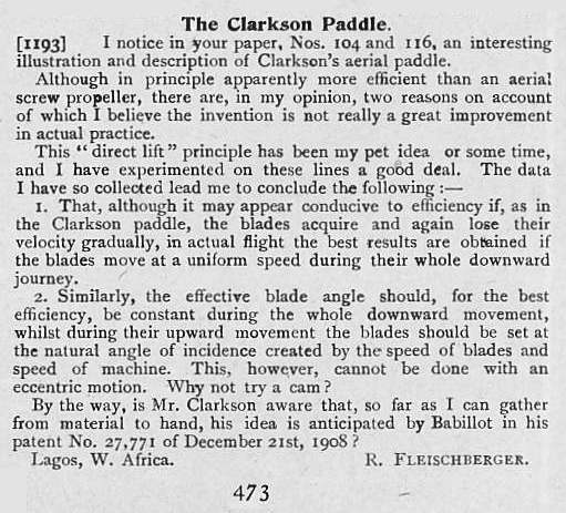 |
| Left: Letter to Flight, 27 May 1910
Clearly Mr Clarkson was in the paddle business as well as Mr Simkins. (above)
However, looks like Mr Fleischburger is going to rain on his parade with the 1908 Babillot patent...
|
 |
| Left: Mr Clarkson's reply to Mr Fleischburger in Flight, 24 June 1910
|
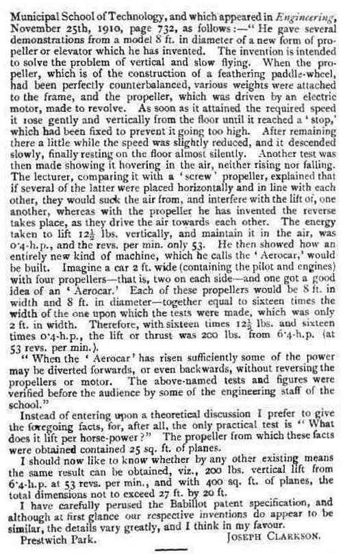 |
| Left: The rest of Clarkson's reply to Mr Fleischburger in Flight, 24 June 1910
I for one am not convinced by Mr Clarkson's airy dismissal of the 1908 Babillot patent.
|
 |
| Left: The Schroeder S1 Cyclogyro: 1930
The Schroeder machine retained its normal wings, and so looked like
an ordinary high-wing monoplane, except there were two large
paddle-wheels in front instead of a propeller. The aircraft was powered by a Henderson engine. Vertical takeoff would be out of the question with the lift concentrated at the front, and so it appears that Schroeder was merely planning to use the rotary wings as a more efficient alternative to a propellor. In this he would have been sadly disappointed.
E A Schroeder was based in San Francisco, USA.
|
|
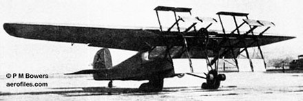
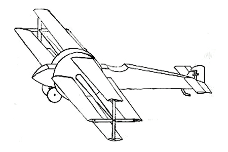
| Left: The Rohrbach Cyclogyro: 1933
This proposal was based on experiments in Germany by Adolf Rohrbach with the paddle-wheel wing arrangement. As in the big picture above, the wings were altered from positive to negative angles of attack during each revolution, and would in theory produce any combination of horizontal and vertical forces. There appears to be no evidence that this design was ever built, let alone flown.
Note the tall thin fuselage required to lift the rotary wings clear of the ground, and that the wings appear to be going round in the opposite direction from the other machines on this page.
|
|
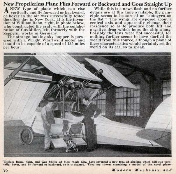
| Left: Cyclogyro by the Rahn Aircraft Corp: 1933
This experimental aircraft was only 15 feet long, and carried two 6-foot span rotating wings on each side; once again these would theoretically allow the aircraft to rise or descend vertically, and fly forwards at up to 100 mph without the aid of a normal propeller. (The article here says 135 mph) It was powered by a 240 hp supercharged Wright Whirlwind. No information appears to exist on whether it ever got off the ground.
From Modern Mechanix March 1933
|
|
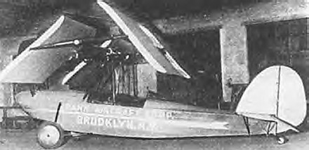
| Left: Cyclogyro by the Rahn Aircraft Corp: 1933
|
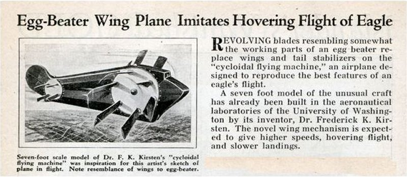 |
| Left: Projected cyclogyro: 1934
Dr Frederick Kirsten was no lone nutter but a highly respected academic and engineer at the University of Washington. The link gives much more info.
A brief quotation from that link:
"By 1923 Kirsten had been promoted to full Professor. By nature Kirsten was an inventor. His most famous aeronautics-related invention was that of the cycloidal propeller, which Kirsten spent over 20 years trying to perfect for use on airplanes. At one point, he teamed up with Bill Boeing to further develop cycloidal propellers for both aeronautical and marine applications. Boeing put up $175,000 of his own money to start a company with Kirsten. However, the concept eventually proved to be impractical in aeronautical applications, and the Kirsten-Boeing company failed. It should, however, be noted that cycloidal propellers were viable as a marine propulsion system. Even today, some tugboats are equipped with them."
There is more on marine applications in Wikipedia. Voith–Schneider are the premier manufacturer of cycloidal propellers for boat propulsion and steering.
Article from from Modern Mechanix for October 1934
|
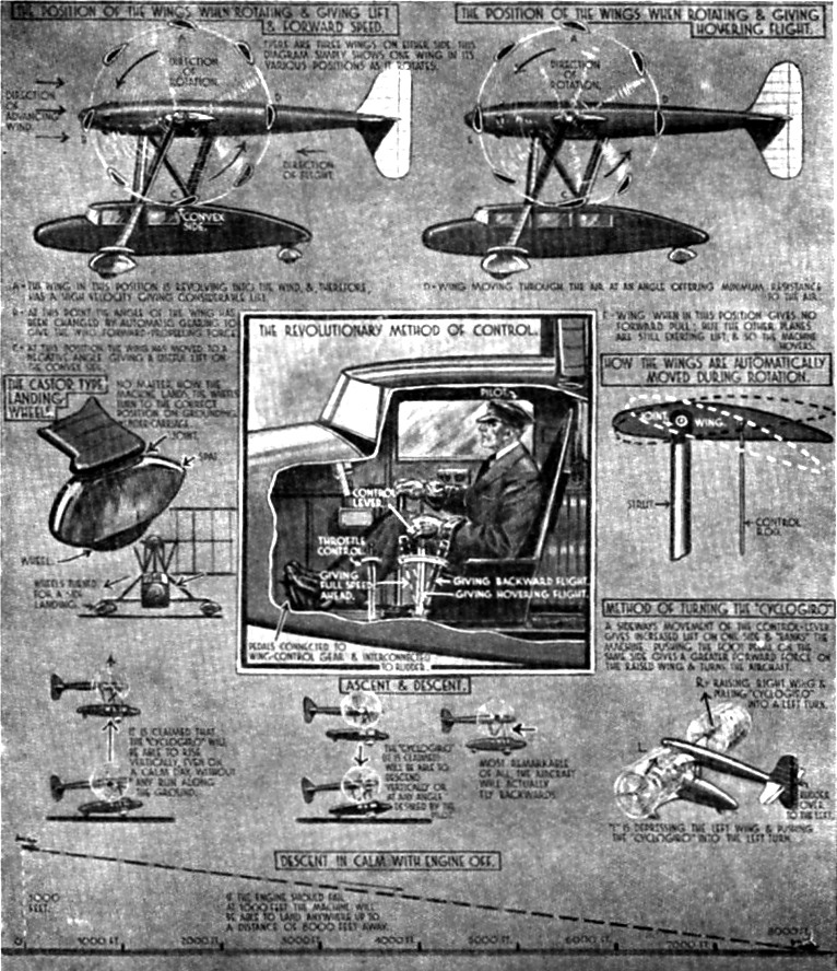
THE CYCLOGYRE PROPOSAL: 1935
|
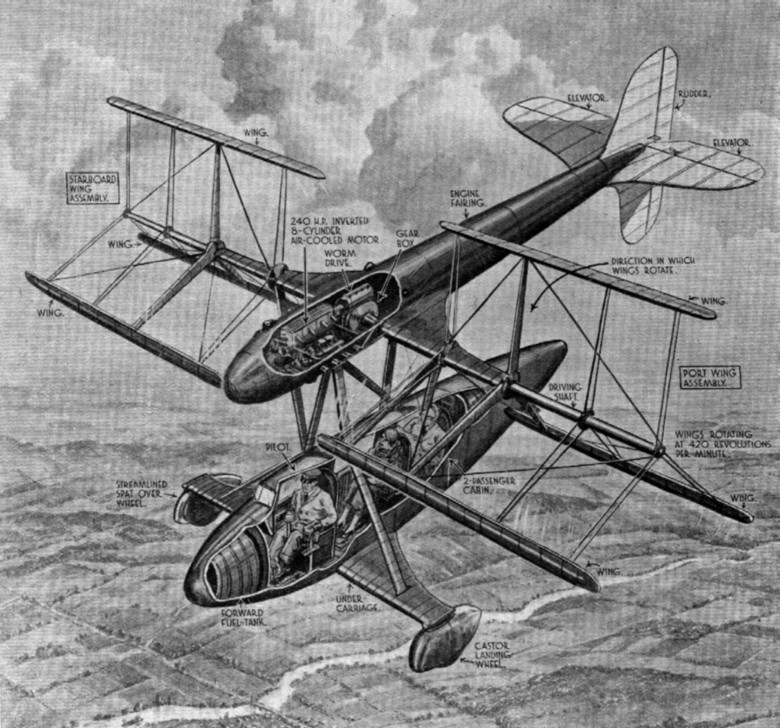
Above: An artists conception of a two-passenger cyclogyre. Picture dated 1935.
|
The essential principle is that the angle of attack of the rotating wings is altered as they go round, allowing the lift/thrust vector to be altered. This (in theory) allows the craft to rise vertically, hover, and even go backwards.
|
Above: How to fly a cyclogyre. Sorry about the poor picture quality; I've done the best I can with it.
|
The picture above describes the cyclogyro principle better than I could: I hope it is readable. The lowest part of the diagram shows (possibly rather optimistically) how a cyclogyro suffering engine failure could still glide to a forced landing. Personally, I think it would have glided like a grand-piano.
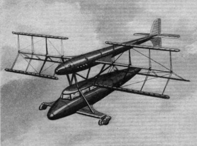 |
| Left: Another speculative view of the cyclogyre, apparently by the same artist.
An inherent problem with this technology is the need to carry the rotors well above the ground. The problem is tackled here by having a second fuselage above the main one.
|
In 1935 NACA wind-tunnel tests were done on a cyclogyro wing, and it was found that theory and reality were somewhat out of line. The power required to turn the rotary wings was much greater than calculated, and would have been impractical.
CYCLOGYROS IN WIKIPEDIA
There is now a Wikipedia page on cyclogyros; it is quite wrong about the history, but it has some good links to recent cyclogyro projects. Its unknown author believes that cyclogyros originated in a patent filed in 1927 by an exceedingly dodgy character called Jonathan Edward Caldwell, who then apparently moved on to ornithopters without even attempting to build a cyclogyro. The second link gives the date of the patent as 1923, and states that Caldwell formed the Gravity Aeroplane Company which issued stock in 1928. Their company letterhead was a crude illustration of a cyclogyro, drawn with the wings at the wrong angles.
|
| Left: Cyclogyro logo of the Gravity Aeroplane Company: 1937?
|
None of Caldwell's designs was ever successful, and after his last business venture in 1939 he disappeared, apparently to avoid charges of securities fraud. His last known project was what he called a "disk-rotor plane", whose wreckage was found at a Baltimore farm in May 1949 by officers of the US Air Force's Project Sign who thought this might explain the "flying saucer" sightings of the day. There are more details here. As a result Caldwell's name later became associated with wholly mythical German flying saucers, and remains a staple of the UFO fraternity today.
As we have already seen, the aerial paddle idea goes back to 1910 at least, with Clarkson's experiments, and maybe 1908 or 1909. (The Babillot patent)

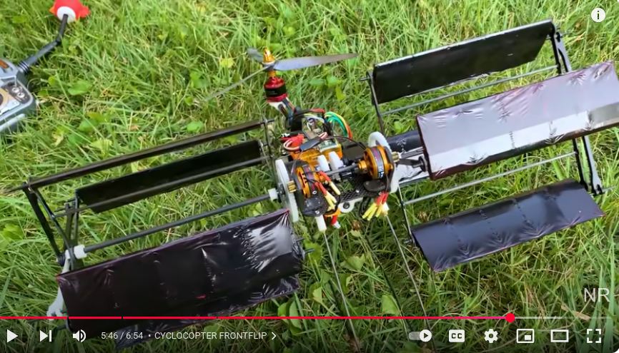
THE CYCLOCOPTER OF NICHOLAS REHM
|
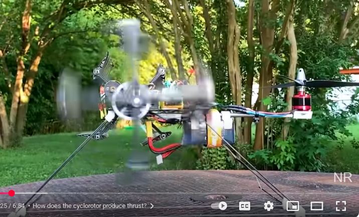
| Left: The Cyclocopter: 2021
Nicholas Rehn has built a very fine model cyclogyro, which he calls The Cyclocopter.
You can see the YouTube video here
Note the upward propellor at the back which gives control in pitch. I imagine that is controlled automatically.
Thanks to Bernd Frieboese for drawing my attention to this machine.
|
|
| Left: The Cyclocopter: 2021
This is a side view of the Cyclocopter with the rotors moving.
|
THE BLACKBIRD TAKES OFF
|
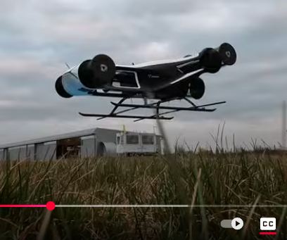
| Left: The Blackbird: maiden flight on 27 March 2025
Here is a real-life flying full-size cyclogyro. The Blackbird cyclogyro was built by CycloTech GmbH, which is based in Linz, Austria, and has a subsidiary in Bavaria, Germany.
You can see the YouTube video of its Maiden Flight here
Thanks to Bernd Frieboese for drawing my attention to this machine.
|
If you really want to dig into the various paddle-wing proposals, I suggest you download USAAVLABS Technical Report 69-13, (1969) which is a mine of information, and a full 431 pages long:
Review & Preliminary Evaluation of Lifting Horizontal Axis Rotating-Wing Aeronautical Systems


