 |
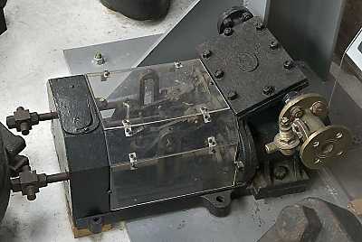
| Left: A two-cylinder water engine, once used to the power the organ bellows of St George's church in Preston, Lancashire.
Photographed in the Manchester Science Museum.
Having inspected it in situ, I believe it operated as follows. There are two cylinders to the left, with a sloping valve-chest on top. The piston rods incorporate scotch cranks that turn a central shaft, whose only function appears to be operating the water valves by two eccentrics. It appears that a reciprocating power output to the organ bellows was taken from the extended rods at the right. The cranks were presumably at 90 degrees to avoid dead-centre problems but this is not clear from this picture.
Since there was not, as far as I can discover, a high-pressure network in Preston, this engine must have run from the ordinary water mains. Since it would have been virtually silent in operation it looks like a good choice for working in a church.
|
Most organ engines worked from the normal mains, especially in areas like Yorkshire where water was plentiful. (An example is Keighley Parish Church) This could have pressures up to 40 psi. In some places, there was insufficient pressure to reliably operate the several hydraulic engines needed for a large organ- services on Monday could be problematical because this was the traditional washday and demand for water by housewives reduced the mains pressure. Some water companies tended to reduce pressure or shut off supplies for maintenance on Sundays just when the need of churches was greatest.

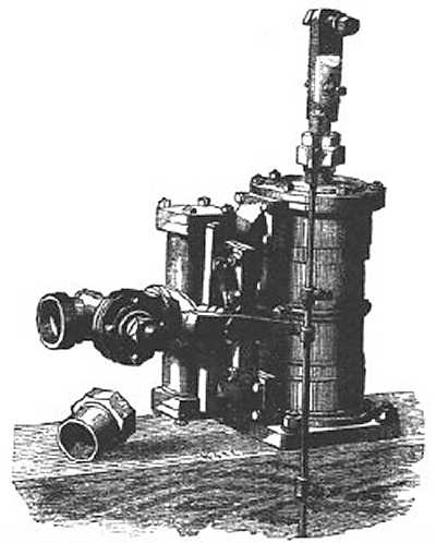 |
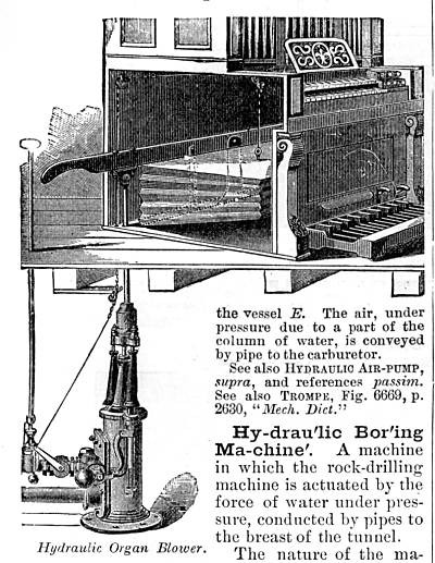
| Left: The Joy Organ Engine: 1856
The use of water engines for powering organ bellows was introduced by David Joy, the railway engineer, who went on to invent Joy's valve-gear for steam engines. Allegedly the stimulus for this invention occurred when he was asked to hand-pump an organ in the house of a relative. Around 1856 he took out the first of three patents for water engine organ-blowers. The first large-scale installation was at the Leeds Town Hall, where an array of five engines powered a giant organ with some 6,500 pipes. Joy engines were also used at the Crystal Palace in London.
The engine shown here has a single double-acting cylinder. The output was reciprocating, not rotary, so it could be connected directly to lever-operated bellows. The valve chest is to the left; the water supply was shut off by a valve when the air reservoir was full, probably by the rod in the foreground of the picture.
|
The demand for hydraulic blowing was driven by advances in organ design, bringing in more pipes and higher operating air pressures. In 1837 William Hill introduced a "Grand Ophecleide" stop running at the then unheard-of pressure of 12 inches of water. (0.43 psi) The pressures needed were low compared with other technologies but large volumes of air had to be moved, and even if several men were employed to work the bellows, the work became excessive. At the same time water mains were being laid, working at up to 30 psi, so power was available.
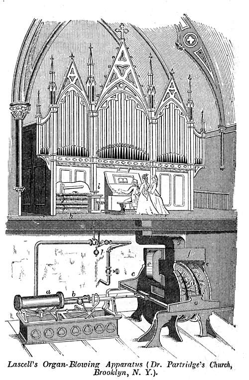 |
| Left: The Lascelles Organ Engine
This shows a water-engine installation in New York by G W Lascell, a name that we have met before. If the drawing is all to scale, the engine cylinder is about 7 feet long, and the bellows in the cellar about 9 feet in diameter. This seems a bit on the large side to me, but then IANAOD, (I am not an organ designer) and it may be that the engine moved quite slowly.
The date of the installation is currently unknown.
From Knight's Dictionary of Mechanics, 1884 edition.
|
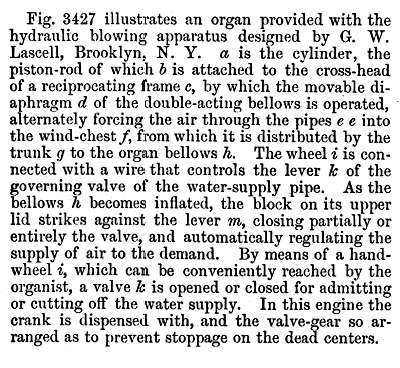 |
| Left: Details of the Lascelles Organ Engine
The "organ bellows" h is presumably the original hand-operated bellows used before the water engine was installed, later used as a pneumatic accumulator to prevent air-pressure fluctuations when the water engine reversed direction.
From Knight's Dictionary of Mechanics, 1884 edition.
|
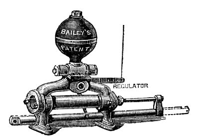 |
| Left: The Bailey Patent Organ Engine
This engine uses a double-acting cylinder to oscillate the rod at the bottom of the assembly. This rod would be connnected to the organ bellows; a small lever connected to it operates the valve above the cylinder. The regulator lever is worked by the rise and fall of the air accumulator, controlling the water supply appropriately.
The sphere at the top is an air-vessel to minimise water-hammer.
From Design and Work, 15 May 1880, p441.
|
This engine was manufactured by W H Bailey & Co of Albion Works, Salford, Manchester; they were well-known hydraulic engineers, making hydraulic lifts and hoists. The organ engines were made in different sizes, from 1.75 to 8in cylinder bore. The smallest exerted a force of 120 lb when run from 50psi mains.
"Mr Gandy, Professor of Music, Cheetham-Hill, Manchester, has one of these at work. Messrs Metzler and Co, the great American organ builders of Great Marlborough St, London, have one working in their show-room."
 |
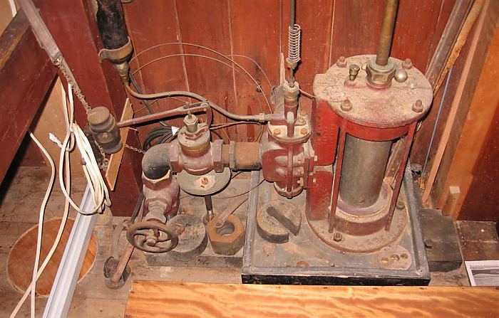
| Left: Unidentified Vertical Hydraulic Organ Engine
This vertical water engine drives directly the hand-lever of the organ bellows. Note the vertical rod for operating the water control valve.
The cord running upwards at an angle is connected to the top of the bellows, which presumably works as an air accumulator; its rise as it fills reduces the flow of power water.
There appears to be a small sphere next to the inlet-pipe; I initially thought it might be an air-vessel to minimise water-hammer, but on closer inspection it appears to be a counter-weight for the valve-gear.
The engine pictured here, assuming it is not just a generic rendering, most resembles the Ross engines described below. These do not, however, have the three conical things on top of the cylinder. They may be stuffing glands, but if so, why three of them?
From Practical Dictionary of Mechanics (supplementary volume) by Knight, Cassell 1884
|
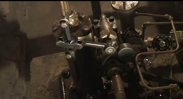 |
| Left: Church Organ Blowing Engine by John Barr, engineers, of Glasgow: 1909
This engine powers the bellows of the Norman & Beard organ at St Munn's Church, Kilmun, Argyll and Bute, in the west of Scotland. The organ was installed in 1909, and the water engine at the same time. You can see an excellent video about the organ and waterengine on YouTube. This is believed to be one of only two churches in Scotland driven by water engine. The other is in St Mary's Episcopal church in Dunkeith, Scotland.
This installation was drawn to my attention by Frank Barclay, the organist at St Munns.
|
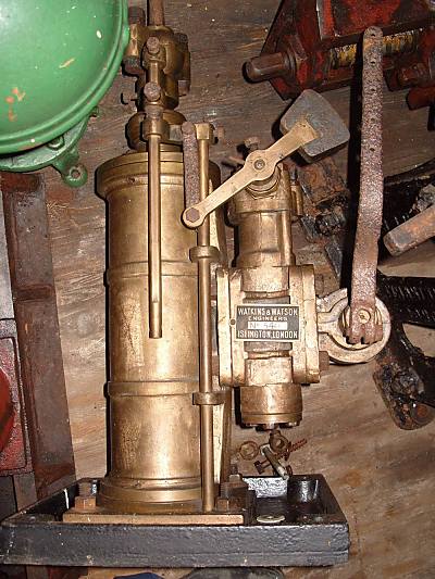 |
| Left: Church Organ Blowing Engine by Watkins & Watson of Islington, London: 1905
The engine is on its side and is seen looking from above. The power cylinder is at the left, with a rod attached to the piston shaft to operate the valves, which are inside the central cylinder that bears the maker's label. The wedge-shaped weight is presumably involved with the valve operation; since the engine is on its side this weight is not acted on by gravity, so presumably its inertia was being utilised. The stop/run water control valve to the left is fitted with a perforated lever that could be operated remotely by wire or cord.
This engine was installed in 1905 to power the 1895 Harrison and Harrison organ in Sherburn Hospital Church near Durham. It was replaced in 1931 by an electric blowing plant, and the water engine now forms part of the collection at Ryhope Engines Museum, Sunderland.
Photograph by kind permission of Keith Bell of the Ryhope Engines Museum.
|
ROSS WATER ENGINES
 |
|
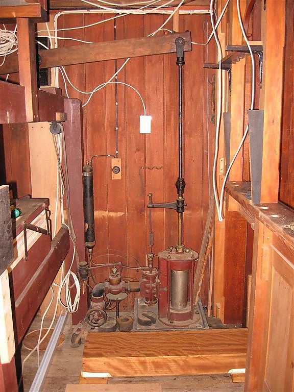
Above: Ross blowing Engine installed and running in a church in Feilding (a small country town in New Zealand)
The power cylinder is at the right. To the left of it is the valve chest, with two rectangular ducts to the ends of the cylinder. To the left of that is the control valve, with a vertical spindle driven by a rocking arm. This arm has a black thing looking rather like hammer-head attached at its left end, which is presumably a weight. The control valve is worked by the height of the bellows via a small chain, but the details of this are not visible. To the left of the control valve, the supply pipe has a right-angle bend, and the water stop valve is just below this.
Date of engine currently unknown, but it is now identified as a Ross engine; see below.
Photograph courtesy of The South Island Organ Company
|
 |
| Left: Ross blowing Engine in New Zealand
This view shows the wooden beam that drives the bellows, and also shows how the valve spindle is driven from the piston rod; the valve spindle is only moved at each end of the piston stroke. Note the two shock-absorbing coil springs on the valve spindle.
The air-storage bellows, with white flexible material, can be seen to the left.
Photograph courtesy of The South Island Organ Company
|
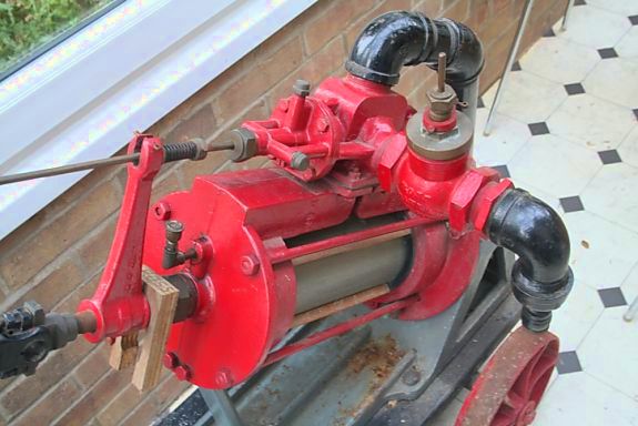 |
| Left: Ross Water Engine
This Ross water engine is clearly the type shown in the New Zealand installation above. It came from Gravesend last year; whether it was still in use there recently is uncertain, but it was definitely used for organ blowing.
The valve box is on top of the cylinder. To the right is the inlet control valve with "Ross" embossed on its body. The water outlet is the black right-angle connection on top of the valve box.
Once again you can see a shock-absorbing coil spring on the valve spindle.
Photograph by permission
|
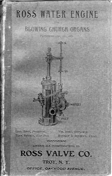 |
| Left: The cover of the Ross water engine catalogue
Note the stops on the valve rod labelled "S" and "SS"
This reveals that the Ross Valve company was an American operation. They also made pressure-regulating valves for steam and water, water relief valves (to prevent water-hammer) and feed-water filters.
Extract from the text inside the catalogue:
"Over five thousand in use"
"TWELVE YEARS AGO we confidently offered this engine to the public, assured that a trial would substantiate our claim that no Hydraulic Motor, either rotary or reciprocating, would develop as much power from the amount of water used, or that would equal it in its adaptability to the work it was designed, (sic) namely, blowing church organs."
which seems to prove that there was such a thing as a rotary water engine.
Photograph by permission
|
The Ross company was still making water engines in the later half of the 20th century. The images below are taken from a booklet entitled "Ross Hydraulic Booster Pump: Installation, Operation, Maintenance". It is undated but the general appearance suggests the 1950's or early 60's. The company was still at Troy, New York.
 |
| Left: Ross hydraulic booster pump
The purpose of this water-powered pump is to generate a high-pressure water supply from a low-pressure one. The piston of the engine section (top) is larger than that of the pump (lower) allowing pressure to be stepped up, though the amount of water moved is of course correspondingly less.
The drawing shows the engine piston to be twice the diameter of the pump piston, so the area ratio, and hence pressure increase, would be four times.
Image courtesy of Vito Pagano
|
The Ross company still exists. It now makes flow control valves.
HYDRAULIC BLOWING AT NEWARK
Here is an example of the rise and fall of hydraulic blowing at St Mary Magdalene church at Newark, Nottinghamshire:
When the organ was renovated in 1909, the options for providing blower power were considered. Electricity would have been ideal, but there was no public supply locally at the time. The cost of gas was thought to be too high, and a gas-engine would have been noisy. The organ builders recommended water power; however the ordinary water supply was at only 40 psi, which would have demanded the consumption of 1000 gallons per hour, so the Corporation was asked to lay a special pipe from a main on Muskham Road to the church, giving water at double the standard pressure. In 1927 the reduction in water pressure owing to industrial and domestic demands was starting to cause problems with the hydraulic machinery, and it was replaced by an electric blower, a supply then being available.
HYDRAULIC BLOWING IN CHICAGO
The record below of the Lincoln Park Presbyterian Church in Chicago suggests that water-motors were sometimes used to blow organs; given the low torque output a good deal of reduction gearing would have been needed. Possibly this is a misunderstanding and a positive-displacement motor was actually used:
"Johnson & Son are credited with being one of the first organ builders in the USA to use a water motor to provide the organ's wind supply. This type of hydraulic motor depended on a reliable water supply of sufficient pressure to operate a water wheel which was connected to the bellows through a series of shafts, wheels and gears. The Lincoln Park organ was built with such a water motor. There was a recital in the church on June 15, 1888, and the church records note: "if all Lakeview will insist on sprinkling their flower beds just as Mr. W. sits down to the organ, he cannot be expected to get much volume of sound. A water motor may be a very good idea, but it's not as reliable as the old-fashioned pumping machine, i.e., a man."
HYDRAULIC BLOWING AT AVERHAM
 |
| Left: The Averham water engine in situ
The church of St Michaels & All Angels, at Averham, Nottinghamshire has an organ with a hydraulic engine. The organ was installed in 1901, and a hydraulic engine would have been a natural choice before the development of electricity distribution; hand-blowing was also installed.
The maker of the engine has not been identified but a restoration consultant reports that it is generally simiiar to Watkins and Watson engines.
Water enters through the valve at top right, and leaves through the pipe at bottom right, which incorporates a throttle-valve on the exhaust side.
|
 |
| Left: The Averham water engine under test
The tappet rod on the right controls the water inlet valve.
|
MISCELLANIA
Those who have seen the museum gallery of rotary steam engines will be wondering if there was such a thing as a rotary water motor. Whether one was actually built is currently uncertain but on 8 January 1878 the following patent was issued to two citizens of Brooklyn:
J.H. SWARTZ, assignor to himself and W.G. WINANS - Rotary water motor
Two USA manufacturers making water motors were the Backus Water Motor Co. of Newark, NJ, and the Colton company.


