Thermo-Electric Generators
|
| |
Thermo-electric generators convert heat directly into electricity, using the voltage generated at the junction of two different metals. This sounds like an excellent way to generate electric power; there are no moving parts, no working fluids, and very little to go wrong. Unfortunately the process is inefficent, and is not going to displace steam turbines. The output is DC, which is not helpful if you want to use a transformer to change the voltage. Nonetheless, thermoelectric generators were and are used where their special characteristics are needed.

THE SEEBECK EFFECT
 |
| Left: Thomas Johann Seebeck (1770-1831)
The history of thermoelectric generation begins in 1821 when Thomas Seebeck found that an electrical current would flow in a circuit made from two dissimilar metals, with the junctions at different temperatures. This is called the Seebeck effect. Apart from power generation, it is the basis for the thermocouple, a widely used method of temperature measurement.
In 1821 Seebeck found that in a closed circuit of using two different metals, if one of the soldered junctions between the metals was heated, then a magnetic needle positioned near the circuit would be deviated, indicating a magnetic field. The deviation angle was proportional to the temperature difference between the hot and cold junctions. It is accepted today that Seebeck was not the first to discover the effect, it had been noticed by Alessandro Volta in 1794. Seebaeck was however the first to make a detailed study of the phenomenon.
Seebeck thought that the magnetic field was being generated directly by the heat. The Danish physicist Hans Oersted, who had discovered that electric currents produce magnetic fields, demonstrated that the heat caused an electric current, which in turn generated the magnetic field that displaced the needle. He named this effect thermoelecricity. It was Oersted who brought thermoelectricity to the attention of several French scientists, such as Becquerel father and son, and Fourier, Melloni, Pouillet, and Nobili.
|
 |
| Left: A list of Seebeck coefficients
The voltage produced is proportional to the temperature difference between the two junctions, and is usually measured in tens of microVolts per degree K. The proportionality constant is called the Seebeck coefficient, and is usually quoted as a relative coefficent compared with platinum, as it is hard to measure ansolute values.
A series-connected array of thermocouples was known as a "thermopile", by analogy with the Voltaic pile, a chemical battery with the elements stacked on top of each other. The maximum power is obtained from a thermopile when its load resistance is equal to its internal resistance, as with all electrical sources. Since the internal resistance of a chain of thermocouples is very low, this means that it can supply big currents but only low voltages, unless a large number are wired in series. Not all thermopiles were used for power generation; small versions fitted with a distinctive brass horn were used to measure infra-red radiation.
Seebeck used bismuth and copper in his original junctions, which gives a coefficient of 6.5 + 72 = 78.5 uV/K. He went on to rank 28 materials in order of effectiveness. The popular combination of bismuth and antimony gives an output of 47 + 72 = 119 uV per K, nearly twice as much.
In 1929 the Russian Abram Ioffe showed that some semiconductors have a Seebeck coefficient much higher than metals or their alloys. This eventually led to The Russian Lamp in 1959.
|
HANS OERSTED AND THE THERMOPILE
 |
| Left: Hans Christian Oersted (1777–1851)
Oersted, working with Joseph Fourier, produced the first multiple-junction thermopiles intended to generate power. A description was published in 1823.
Regettably no illustrations of these early thermopiles have been found so far.
|
GEORGE SIMON OHM AND THE THERMOPILE
 |
| Left: Georg Simon Ohm (1789-1854)
George Simon Ohm was probably the most famous thermopile user. In 1825 he was working on the relationship between current and voltage by connecting wires of differing resistance across a voltaic pile- pretty near short-circuiting it. After an initial surge of current rapid polarization of the pile caused the voltage to decrease steadily, greatly complicating the measurements. Ohm took a colleague's advice and replaced the voltaic pile with a thermopile, and the results were much better.
|
This use of a thermopile is only four years after the discovery of the Seebeck effect, so the idea of the thermopile must have been quickly developed. I have not so far been able to identify the first use of the effect for power generation rather than measurement, but this case must be a candidate.
As an aside, Ohm's law met with a very cool reception in his own country; one account soberly states: "Unfortunately, Ohm's law was met with resistance." The Prussian minister of education pronounced that "a professor who preached such heresies was unworthy to teach science." This is the sort of thing that happens when politicians try to involve themselves in science, and in that respect we have progressed little since then.
THE EARLY HISTORY OF THERMO-ELECTRIC GENERATORS
Here are displayed some early thermo-electric generators or "thermopiles". I have tried to put them in chronological order but not all have a definite date, so this is rather iffy.
The Danish physicist Oersted and the French physicist Fourier invented the first thermoelectric piles around 1823, using pairs of small antimony and bismuth bars welded in series.
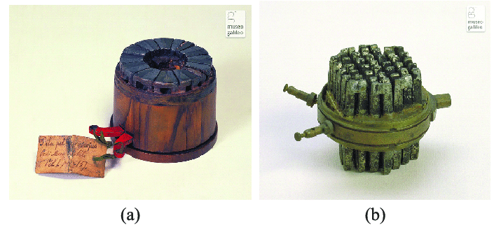 |
| Left: Thermopiles by Nobili and Melloni: circa 1829/1831
The thermopile was further developed by Leopoldo Nobili (1784-1835)and Macedonio Melloni (1798-1854). They initially used it for the measurement of temperature and infra-red radiation, but the thermopile was also rapidly put to use as a stable supply of electricity for other physics experimentation, such as Ohm's experiments.
a) Nobili prototype built ca 1829, using bismuth and antimony for the couples, giving an output of 47 + 72 = 119 uV per K. If we take red-hot as 900 degC, that gives an output of around 100 mV per couple, demonstrating why it was necessary to use a lot in series to get a useful voltage. The vertical bars linked at the upper ends can be seen. There are twelve large bismuth and antimony elements which were placed upright in a brass ring secured to an adjustable support, and and screened by
a wooden disk with a 15mm central aperture. Nobili built a large number of thermopiles, ranging from 6 to 200 elements of bismuth and antimony, using to supply a steady current for his galvanmeter experiments; he called them 'thermomultipliers'.
b) Incomplete Nobili-Melloni thermopile from ca. 1831. Some accounts state that Melloni introduced the idea of using bismuth-copper as a couple, but others say that the effectiveness of antimony-bismuth had already been discovered by Nobili and Oersted. Melloni was intersted in using his thermopile for temperature measurement rather than power generation. His instruments used blocks of up to 38 bars, each 20mm long and 1 or 2 mm wide.
Both are in the Museo Galileo-Institute and Museum of the History of Science, in Florence.
|
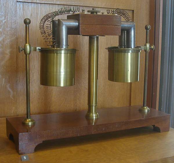 |
| Left: Thermopile by Pouillet: circa 1840.
This, I think, is an early thermopile. Unfortunately I have no details on it, and its operation is obscure. It is not clear where the heat is applied; perhaps one brass tank held hot water and the other cold? If so, that would be a much less effective source of heat than a gas flame.
In each tank, one of the L-shaped pipes appears to go into a glass vessel, for reasons unknown.
Example in CNAM, the Conservatoire National des Arts et Metiers, in Paris. Author's photograph.
|
 |
| Left: Claude-Servais-Mathias Pouillet: (1790-1868)
Claude Pouillet (1790-1868) was a pioneer in the detection of infra-red radiation. He used a "pyroheliometer"- essentially a water calorimeter- to measure the intensity of solar radiation. The apparatus shown above is NOT the pyroheliometer; however it may be some sort of measuring instrument rather than a power source as such.
Pouillet used an iron-platinum couple.
|
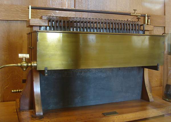 |
| Left: Thermopile by Ruhmkorff: circa 1860.
The gas burners are inside the black body of the device; the spigot for the gas supply pipe is at lower left. The brass tanks hold the cooling water for the cold junctions.
An interesting feature is the sliding contact at the top, which allows the output voltage to be altered by connecting a variable number of junctions into the circuit. The output terminals are at top right.
Heinrich Daniel Ruhmkorff, electrical researcher and instrument maker, is best known for the remarkable improvements he made in the induction coil. However, it appears he was also in the thermopile business.
Ruhmkorff was born on 15 January 1803, in Hanover, Germany, and died 20 December 1877, in Paris.
Example in CNAM, the Conservatoire National des Arts et Metiers, in Paris. Author's photograph.
|
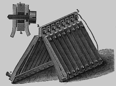 |
| Left: Markus's thermopile: 1864.
The EMF of a single couple was quoted as "One-twentieth of a Daniel cell" which makes it about 55 milliVolts. The negative metal was a 10:6:6 alloy of copper, zinc and nickel, similar to German silver, and the positive metal was a 12:5:1 alloy of antimony, zinc and bismuth. The iron bar a-b was heated and the lower ends cooled by immersion in water. A defect of this design was a rapid increase in internal resistance as the two alloys oxidised at their point of contact.
Markus' thermopile won a prize in 1864/5 from the Vienna Society for the Promotion of Science.
From "Electricity in The Service of Man" published in its 3rd edition in 1896; the thermopile section appears to have been written much earlier, and certainly before 1888. It was originally published in Germany and was written by Dr A R Von Urbanitsky.
|
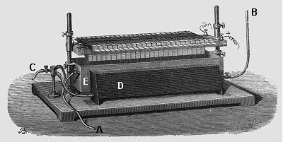 |
| Left: Becquerel's thermopile.
This was invented by M. Edmond Becquerel (1820-1891), at a date unknown. The junctions were composed of copper sulphide for one metal, and German silver for the other.
It appears that D is a trough of cooling water for the cold junctions, supplied at B and exiting at C. There appears to be another trough on the other side of the central burner E. Gas for the burner is supplied via pipe A.
Edmond Becquerel was the father of physicist Henri Becquerel, who discovered radioactivity
From "Electricity and Magnetism", 1891.
|
M G Farmer exhibited two of his thermopiles at the Universal Exhibition of 1867 in Paris. These piles used “German silver” (Cu 60%, Ni 20% and Zn 20%) as the negative material, and an antimony-zinc alloy for the positive material. Farmer piles were used in industry for several years, but the rapid loss of output over time and the fragility of the thermoelectric bars prevented their widespread use.
No pictures of any of Farmer's thermopiles have so far been found.
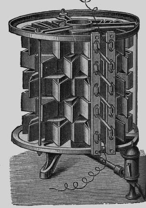 |
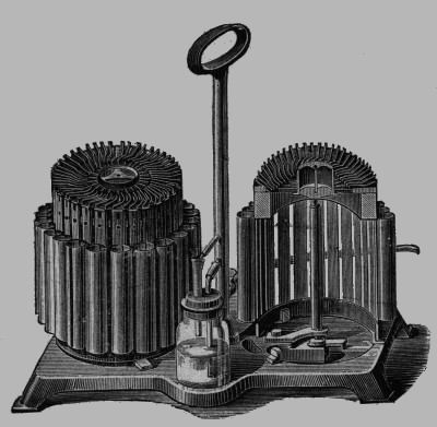
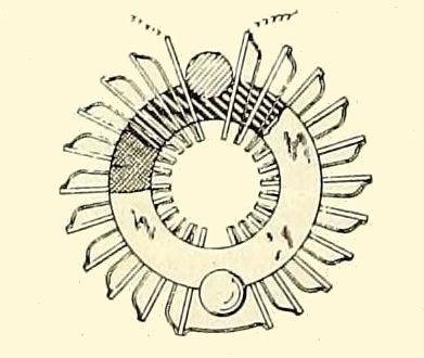
| Left: The Clamond Thermopile: .
This pile, developed by Charles Clamond in association with Louis Mure, used a zinc-antimony alloy for one metal and iron as the other. It was gas-fired, and could liberate 0.7 oz of copper per hour by electrolysis while consuming 6 cubic feet of gas in the same period. The output current was quoted in this outlandish fashion because electroplating was the main application of these devices; possibly practical ammeters did not yet exist.
The diagonal connections that join each ring of couples in series can be seen between the two vertical strips.
The gas pipe can be seen coming in from bottom right. The little coffee-pot thing in the line is actually a gas pressure regulator.
From "Electricity in The Service of Man"
|
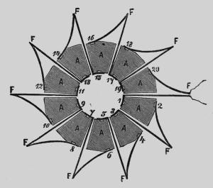 |
| Left: The Clamond Thermopile: plan view.
The solid sectors A were made of the alloy, while the cooling fins F were made of sheet iron to act as cooling fins for the cold junctions.
From "Electricity in The Service of Man", a much longer book than "Electricity in The Service of Chameleons"
|
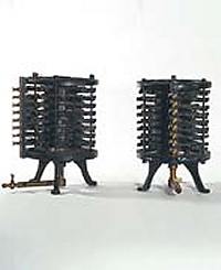 |
| Left: The Clamond Thermopile: reality.
Note gas feed with tap running into the centre of the pile.
This example is in the History Museum of the University of Pavia in Lombardy, Italy.
|
 |
| Left: The Clamond Thermopile: section.
Showing the multiple annular burners in the centre of the pile. Gas enters through tube T.
According to the French journal La Nature for 1874, one of these piles was in use at the printing works of the Banque de France, presumably for electroplating.
Picture from La Nature 1874.
|
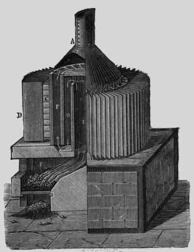 |
| Left: The Improved Clamond Thermopile: 1879
The EMF of this pile was no less than 109 Volts, with an internal resistance of 15.5 Ohms. The maximum power output was therefore 192 Watts, at 54 Volts and 3.5 Amps.
This pile was fired by coke. The hot junctions were at C, while the cold junctions D were cooled by sheet iron as in the original design above. What purpose was served by the tortuous path T-O-P taken by the hot gases is unclear, because there seem to have been no hot junctions in the inner sections. This beast was 98 inches high and 39 inches in diameter. It was a very serious piece of machinery, quite capable of delivering a lethal voltage.
The second version of the Clamond and Mure pile used the alloy of Marcus (Zn 66.6% and Sb 33.3%) for the negative material, and iron for the positive material. It surpassed all other similar piles and won the Gold Award of French National Industry. In 1876, the "Thermo-Electric Generator Company" (France) began the mass production of Clamond's thermopiles. But soon it turned out that generators had serious problems: the thermocouples melted, oxidized rapidly, and exfoliatied. This affected the pile's efficiency...
Clamond needed four years to develop new thermoelectric materials and improve the construction of the vulnerable elements. His new "Clamond Improved Thermopile" was based on the alloy of bismuth and antimony (negative material) and on iron (positive material). This efficient and powerful generator was 'free of all imperfections of its prototypes' and was the considered the best pile of that time.
On May 1879, the new Clamond's generator was presented to the French Academy of Sciences.
From "Electricity in The Service of Man"
Further details come from Rankin Kennedy. The pile shown here was described by Clamond before the Paris Academy in 1879. It had 3000 elements, and at 20 elements to generate 1 Volt it should have given 150 Volts unloaded. It consumed 22 pounds of coke per hour.
From Volume 4 of "Electrical Installations" by Rankin Kennedy
|
This extract comes from Electric Light, Its Production And Use by John W Urquhart.
CHAPTER III. THERMO-ELECTRIC BATTERIES
"The two most efficient thermo-electric piles in use up to 1876 were probably those of MM. Clamond and Noe; great numbers of such pairs being employed to multiply the force and current. By the expenditure of 21 lbs. of coke per hour, M. Clamond, of Paris, has succeeded in maintaining four electric lights, each having an illuminating- power of 220 standard candles. This is vouched for by the Count du Moncel; and, indeed, there should be nothing impossible, or even difficult, in the accomplishment of such a result. Sixty couples will yield, when well constructed, a current equal to a gallon Bunsen cell, and less than 3,000 elements will give the effects of 50 Bunsens with an expenditure of 80 cubic feet of gas per hour."
"Such results are reported of the couples of M. C A Faure. M. J E M Sudre, who has been working in conjunction with M. Clamond, has taken out a patent for advances in the makeup of thermo-electric batteries."
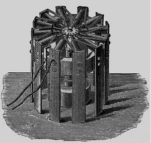 |
| Left: The Noe Thermopile
The hot junctions are the pointed things directed inwards to the central burner. The cold junctions are cooled by radiation and convection from the vertical strips on the outside.
The inventor, Fr. Noe, came from Vienna. The output EMF of this pile was about 2 Volts, with an internal resistance of 0.2 Ohm. This was for a pile with 128 couples.
From "Electricity in The Service of Man".
|
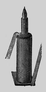 |
| Left: One thermocouple from the Noe Thermopile
The hot junction is a copper pin in a brass case, surrounded by "an alloy" which is presumably the other half of the junction.
The connecting wires visible here on each side were of "German silver". German silver (better known nowadays as nickel silver) is the generic name for a range of bright silver-grey metal alloys, composed of copper, nickel and zinc; it contains no real silver.
These wires were essential to join the thermocouples together, but reduced its efficiency as they conducted heat away from the hot junctions to the cold ones. The problem is elegantly solved in modern semiconductor versions by using alternate P and N type materials that do not require these connections.
From "Electricity in The Service of Man".
|
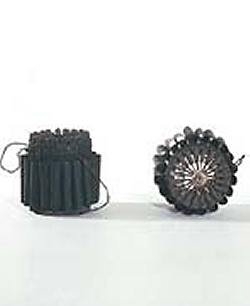 |
| Left: The Noe Thermopile in reality
This high-performance version is surrounded by little cylindrical fins for cooling the cold junctions, permitting a greater output.
This example is in the History Museum of the University of Pavia in Lombardy, Italy.
|
 |
| Left: Hauck's thermopile
The EMF of a single couple was quoted as "0.1 of a Daniel cell" which makes it about 110 milliVolts; this seems rather high to me. The current capacity using 30 couples was "capable of making a platinum wire 1.2 inches long red-hot" which is not a very useful sort of spec, since we have no idea how thick the wire was.
The Hauck pile was fired by gas, using something looking very much like a Bunsen burner. The cold junctions were water-cooled by a series of little cylindrical tanks, and there was an obscure little glass device in the middle; possibly to show the rate of gas flow?
These devices appear to have been produced commercially in different sizes, with two or three placed on a common frame. They were used for science education and electroplating. To put a time marker on this, it was 1843 when Moses Poole took out a patent for the use of thermoelectricity instead of batteries for electro-deposition purposes. This was long before practical dynamos and alternators.
In the days when chemical cells needed a lot of attention, something that provided power at the strike of a match must have had its attractions.
From "Electricity in The Service of Man".
|
 |
| Left: Article in Nature: Nov 18,1875
Doctor Stone reads an article on thermopiles.
This gives some interesting practical details on the problems of brittle thermocouple materials and the difficulty of avoiding oxidation when iron was used as one half of the couple, as it was in the Clamond pile. There is also the interesting suggestion that petroleum should be vaporised at the cool junctions, reducing their temperature, and the resulting vapour burnt at the hot junctions. However, should there be a bad contact on the cold side, causing an electrical spark, things might end bad.
Attempts to find out more about Dr Stone have so far failed.
This article comes from the English journal Nature, not to be confused with the French journal of the same name.
|
THE COX THERMOPILE
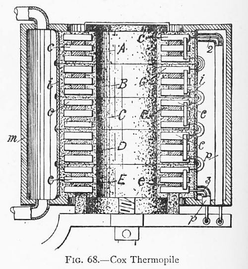 |
| Left: Cox thermopile: 1890
A Cox thermopile as illustrated in Rankin Kennedy's book. He says "Cox's pile, which gained some notoriety..." which raises some questions that are probably now unanswerable. Why is was it notorious? Was it unreliable? Was it inefficient?(Even by thermopile standards)
Kennedy goes on:
"It consisted of bars of a mixture of zinc and antimony, two of antimony to one of zinc, and these bars joined by flexible tinned iron, cast into the end of the bars, same as used in Clammond's pile.
This mixture seems to be the best alloy or metal yet discovered, and, unfortunately, it has very bad properties mechanically and physically. First the mixing and casting of the bars is very difficult; both metals are easily oxidised when melted, and do not readily mix thoroughly; the alloy is as brittle as cube sugar, it is difficult to unite with the other metal, it expands on cooling."
That should be enough to put anybody off, but does not tell us what the other half of the thermocouple was. It does seem to indicate that maintaining electrical conductivity was difficult, and the likely conclusion is that the Cox pile was notorious because it was unreliable.
Kennedy then went on to praise the Gulcher pile.
|
The Cox pile in the diagram follows the usual plan of a hot central core, which appears to be heated by a gas burner. The outer cold junctions were cooled by a water jacket.
The Cox pile was an American product. US Patent 434,428 was garnted to Harry Barringer Cox of New Haven, Connecticut, in August 1890. The thermocouple materials were not disclosed; the patent is about uniformly heating the hot side of the pile.
THE GULCHER THERMOPILE
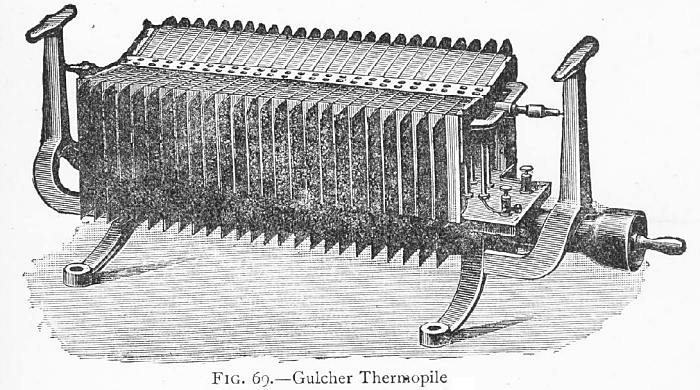 |
| Left: Gulcher's thermopile: 1891
A Gulcher thermopile with fifty couples, giving 1.5 Volts at a current of 3 Amps. The gas comes in through the spigot at lower right, and the two electrical output terminals can be seen to the left of that. I assume the T-shaped things at each end are carrying handles. The function of the two pointy things at the upper ends of the pile is unknown.
Unfortunately there is nothing here that gives a reliable idea of its size.
Note that Gulcher was German, and that "u" should have an umlaut.
|
According to Rankin Kennedy:
"The Gulcher pile has, by good design and construction, overcome many of the difficulties, employing slabs and sheets of metal bound up in a cast-iron frame; it is shown in Fg. 69 with fifty couples, This size gives an external pressure of 1.5 Volts, with a current of 3 Amperes, the internal resistance being 0.5 (Ohms) equal to the external, and in doing this work consumes 5 cubic feet of gas. This return is very small, 5 cubic feet of gas for 4.5 Watts work done, yet its simplicity and convenience go a long way to compensate for the cost. According to this result, 1000 cubic feet of gas would give about 1 B.O.T. (Board of Trade) unit, which in Leeds would cost 2s 3d per hour for gas. The high internal resistance is a great drawback."
The complete complete confusion between energy and power in this passage does not inspire confidence. 5 cubic feet of gas will give 4.5 Watts for how long?
The Gulcher thermopile seems to have been a popular choice around 1900. Lehigh University (PA) boasted in 1905 that their new Electrometallurgical laboratory had "a Gulcher thermopile and three Scott thermopiles for small-current work." The Scott thermopile, which sounds like an American design, is unknown to Google.
From Transactions of the American Electrochemical Society Volume 6, 1903:
"The cell was connected in series with a galvanometer and a 66-element Gulcher thermopile. The thermopile was lighted and simultaneous readings were taken of the current and the electromotive force. The electrodes used were small pieces of gold foil, and the electrolyte was dilute sulphuric acid of 10 per cent, strength. After reaching a maximum of 3.5 volts, the gas was turned off from the thermopile and it was allowed to cool. Simultaneous readings were again taken of the current and the applied voltage as before. As the thermopile cooled, the current dropped steadily and when the voltage had reached 1.5 exactly the current passing reached zero."
This gives a glimpse of a useful feature of the thermopile; the voltage was extremely steady due to the large thermal inertia. Turn off the heat and the voltage will decline slowly and very steadily.
ARTICLE ON THE GULCHER THERMOPILE IN THE TIMES (Friday 2 Oct 1891)
THE FRANKFORT ELECTRICAL EXHIBITION
...Foremost among them is R. Gulcher's thermopile. A thermopile, as your reader will doubtless I aware, is An apparatus for direct conversion of heat into electricity, and no problem of modern electricity has attracted more attention and has been more zealously followed up than the construction of an efficient generating apparatus dispensing with the intermediary conversion of heat into motive powcr.
Many have been the attempts in this direction, and, I am sorry to say, as many the failures. All thermopiles hitherto constructed suffered from two defects; not only did they possess a very small efficiency, but none of them lasted for any length of time. The principle of the thermopile is the following. When two electrically opposite metals are joined together and the place of junction is heated, part of the heat is converted into electricity. A thermopile, therefore, consists of a num ber of elements formed of two electrically opposite metals soldered together, the individual elements being carefully insulated from one another. One of the metals generally employed in forming these elements is antimony, and its brittle character, together with its low point of fusion, have invariably led to the destruction of the thermopile, after a short period of working, through the cracking, bursting, or fusion of the antimony.
The improvements of the Gulcher thermopile consist chiefly in the employment of a positive electrode consisting of an alloy of antimony not easily fusible and very durable; further. in the use of nickel as the negative electrode; and in an arrangement, which I need not describe here, for pretenting the overheating of the place of junction. The remarkable feature of this thermopile is, in addition to its great durability, its great efficiency, greater than has hitherto been ibtained by any similar apparatus. The model shown in operation at the exhibition has an electromotive force of 4 Volts and a current of 5 Amperes, at a consumption of 200 litres of gas per hour The working expenses are, therefore, about one farthing per hour. It will thus be seen that the Gulcher thermopile, per cubic metre of gas, gives a total electrical energy of 100 Watts, whilst the best apparatus of this kind hitherto constructed only gave about 24 Watts per cubic metre of gas. A still higher efficiency than the batteries heated by gas is shown by the batteries intended for production of large electrical energies, and arranged for heating with coke. In these the elements are grouped round a common stove, and other improvements, the description of which would lead me too far, have been adopted, increasing the efficiency.
A thermopile constructed after this principle and consuming two kilogrammes of coke per hour gave 80 Volts and a current of 10 Amperes. A battery of this description would suffice for feeding eight glow lamps or 1C Candles continually, or with the help of accumulators, 30 of these lamps for six hours per day. In other words, such a battery would supply light for a house of moderate size, and not only light but also heat, by placing, for instance, tbe stove in tne basement and heating the house by hot air pipes. The smaller type of this highly interesting apparatus is already in the market, and constitutes an excellent generator for galvanoplastic, chemical, and physical laboratories, for charging accumulators, for working electro-medical and dentists' apparatus, for replacing galvanic batteries in telegraphy and telephony, etc. The large type is at the present moment being tested for its durability, and will shortly be brought onto the market. The apparatus is manufactured by the well-known firm of Julius Pintsch, of Berlin.
 |
| Left: Gülcher's thermopile: c 1898.
Here is a real example in the History Museum of the University of Pavia in Lombardy, Italy. Though not a good image, I'm afraid, it is clear that it is pretty much identical to the drawing above.
|
A THERMOPILE IN THE ENGLISH MECHANIC: 1898
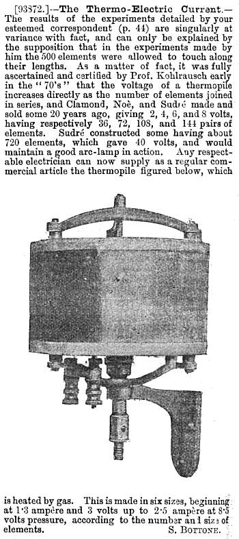 |
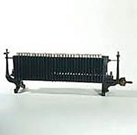
| Left: Commercial thermopile: 1898.
A handy thermopile with wall-mounting bracket. It is gas-fired, with the gas going in through the central spigot. The output terminals are bottom left. Manufacturer unknown, but if it really could be supplied by "any respectable electrician" it must have seen some commercial success. Sudre is mentioned as a constructor; it would be interesting to know more about him, as his name has not occurred before.
Cooling looks like it might be any issue; presumably it relied on convection and radiation from the cylindrical outer surface, as there are no signs of water cooling arrangements. I would have thought that would have reduced its effciency markedly. There are no visible fins to improve cooling.
If the biggest model gave 2.5A at 8.5V, that's a healthy output of 21 Watts; much more than the Gulcher thermopile.
Bottone was a regular contributor to discussions in the English Mechanic at the time.
From English Mechanic 9 Sept 1898, p98
|
AN ASIDE ON EARLY GAS SUPPLY.
Coke-firing is clearly not an attractive option unless you had a big floor-standing thermopile like the Improved Clamond model above. Coal gas was far superior for table-top models. But when did gas supply to buildings start? Here are a few historical nuggets that show that gas could be laid on rather earlier than you might think. But for a year or two, the Duke of Wellington could have written his despatch reporting his victory over Napoleon at Waterloo by gaslight.
By 1819, 288 miles of gas pipes had been laid in London to supply 51,000 burners.
The first commercial town gas supply in the USA began at Baltimore, Maryland in 1816, lighting residences, streets, and businesses.
By 1850, all public lighting in France was by gas.
I have so far no been able to discover when gas was introduced in the German states; can anyone help? Anyway, I think I have shown that a gas supply was in fact ready and waiting for the thermopile.
THERMO-ELECTRIC GENERATORS IN THE TWENTIETH CENTURY
 |
| Left: Yamamoto patent: 1905
This thermopile was patented in Japan in 1905 by one Kinzo Yamamoto. Few other details are known; much information was destroyed in the Tokyo Earthquake of 1923.
The P-type material is made of bismuth, antimony and zinc in the proportions: Bi:Sb:Zn=12.0:48.0:36.8. In the figure, D is a P-type "Bullet" and E is a Nickel electrical connection. (Probably that should be nickel-silver: see above)F is the pin to collect heat flow from the flame. A is an electrical and thermal metal connection. B is a cooling fin.
|
This design has an unmistakable resemblance to the Noe thermopile above; in fact it appears to be a very faithful copy. It was presumably intended for powering radios, but this is pure guesswork on my part.
It appears that Great Britain was rather slow in electrification compared with other European countries. Light could be provided by gas, and heating by coal, but electricity was needed to run radios and a gas-fired thermopile was one way to get it. Alternatively, you took your lead-acid filament accumulator into town to get it charged for you, which was somewhat less than convenient.
THE BOY MECHANIC THERMOPILE
 |
| Left: The Boy Mechanic Thermopile: 1913
This thermopile, having only six junctions and non-optimal metals, would only have produced a very small output.
The Boy Mechanic was a series of books rather than a journal. Some of the projects suggested for young lads were frighteningly ambitious; for example the man (or boy) carrying glider.
Source: The Boy Mechanic, Volume 1, 1913
|
THE WEBB PATENT 1918
 |
| Left: The Webb patent: 1918
It was clear from the early days of internal combustion engines that a lot of heat was being thrown away in the exhaust. Some people thought the way to utilise it was to boil water and generate steam, as in the Simon gas-steam engine or the Still diesel-steam engine. The snag is that this adds a lot of weight and complication, with the added risk of a boiler explosion.
A far better idea (an idea that occurred idependently to me, as well as lots of other people) would be to use a thermopile to generate electricity from the exhaust gases. No extra moving parts, sounds a winner. So why don't we do this? The simple but sad answer seems to be that even modern semiconductor thermopiles are so inefficient that it's just not worth the bother for the relatively small amount of electricity you get.
This annular thermopile was intended to be inserted between the engine block and the exhaust manifold, with the exhaust gases passing through the centre. It would certainly have got hot- probably red-hot. However the cold ends of the junctions are only cooled by their exposure to the air; there no fins or other cooling aids, which suggests to me a certain lack of practicality.
This notion was patented in the USA by Hartwell W Webb in 1918; its claimed innovation was the spot-welding together of the two types of metal (iron for one and nickel-copper for the other, in this case) which would presumably have been a lot more reliable than soldering. Though maybe not when red-hot.
US patent 1,242,499
|
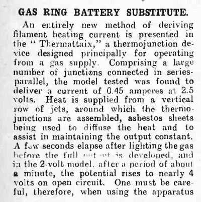
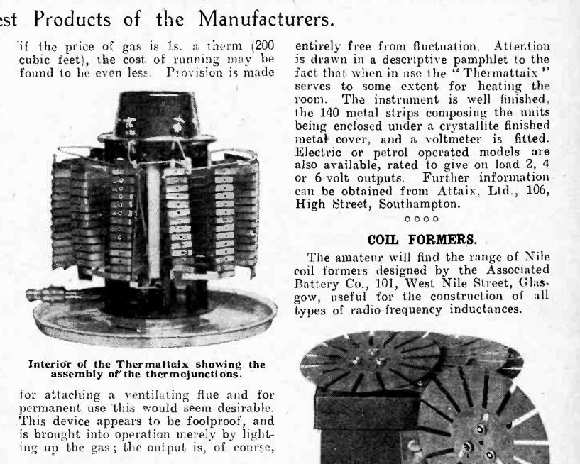
THE THERMATTAIX: circa 1925
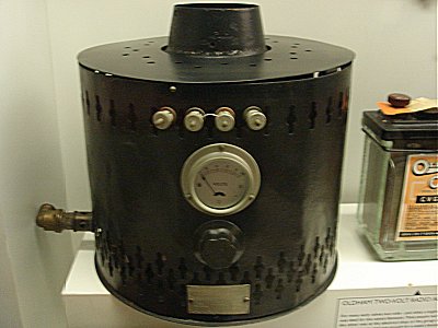 |
| Left: The Thermattaix: 1927
Not a name that exactly trips off the tongue. The voltmeter on the front registers from 0 to 10 Volts; a suitable voltage range for charging accumulators running 6.3 Volt valve heaters. The black knob below the meter obviously controlled something- presumably the gas supply.
It appears this device was designed to charge lead-acid accumulators rather than power the radio directly. This may have been because output voltage fluctuations due to changing gas pressure would have had little effect on accumulators, but would have been very bad for the filaments of valve heaters, a small over-voltage deceasing their life drastically. Note there are four output terminals, in red-black pairs, with a shorting link between them; it appears that the thermo-electric elements were wired in two separate sections, probably to give a choice of output voltage.
The knob under the voltmeter presumably controlled the size of the gas flame and therefore the output voltage.
This example is in the Science Museum in London. It was made by a small Southhampton company called Attaix, hence the strange name.
|
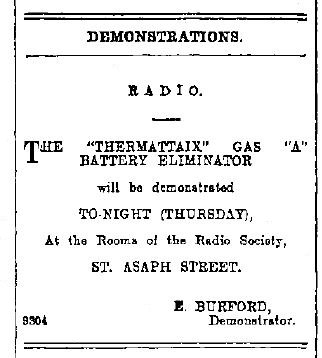
The magazine Amateur Wireless, in April 1929 carried an advert for the Thermattaix, apparently claiming that it could work your wireless set by gas, petrol, electricity or steam. Electricity? That is not as daft as it sounds. If, as was once common, you had a DC mains supply, transformers would not work to generate the filament supply, and rotary converters were expensive and noisy. However DC would work perfectly in a resistive heating element, and the thermal inertia would have removed voltage fluctuations.
The advert goes on to claim that amongst their customers were gas companies, the Italian airforce, architects of note and big game expeditions in Africa and India.
 |
| 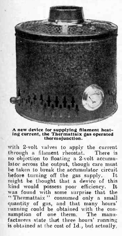 |
| Left: The Thermattaix in Wireless World: 1927
Note that the the junctions were connected in series-parallel, and the output fell from 4 Volts to 2 Volts on load, which is optimal for maximum transfer of power.
This version has only one output voltage and so only two output terminals, mounted on the upper cover.
No gas control knob is visible.
The asbestos inside is rather a worry; in 1927 it was known to be dangerous to work with but no-one knew how dangerous. (In 1906, the first documented death of an asbestos worker from pulmonary failure was recorded by Dr Montague Murray at London’s Charing Cross Hospital) It is interesting that the WW staff thought it was efficient- it cannot have been in any strict sense.
This description appeared in Wireless World in November 1927.
|
 |
| Left: The Thermattaix in Wireless World: 1927
In this part of the description the writer recommends connecting the Thermattaix to a flue. I think that would have been a very good idea, because here we have gas flames playing on cooled metal, which is the classic way to generate highly poisonous carbon monoxide.
This description appeared in Wireless World in November 1927.
|
 |
| Left: The Thermattaix reaches New Zealand in 1928
An A-battery was the low-voltage high-current battery that powered the valve filaments. The B battery provided the HT.
This advertisment appeared on the front page of The Press, published in Christchurch, New Zealand, on 28 June 1928.
|
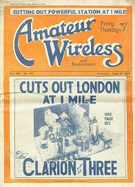 |
| Left: Amateur Wireless 1929
An advertisment appearing in Amateur Wireless magazine claimed the Thermattaix had been supplied to "...gas companies, the Italian Airforce, architects of note, and Big Game Hunting Expeditions for use in Africa and India." One can see how the Italian Airforce might use them to power radios, but far from clear what use they would be on hunting expeditions a long way from the nearest gas supply. Were they supposed to be wood-fired in some way?
|
THE CARDIFF GAS LIGHT & COKE CO: 1930s
The gas-fired machine below, which seems to have no name, but was sold by the The Cardiff Gas Light & Coke Company, was brought to my attention by John Howell, who says that his father sold a number of these when working in South Wales during the 1930's; that's what triggered this page. I must admit that I had never heard of such a thing in Britain before- they must have been fairly rare. I would have thought that by 1930 the provision of mains electricity would have been well advanced. However, apparently not.
The Cardiff Gas Light & Coke Co appear to have acted as agents for this machine as it was built by Milnes. (see just below)
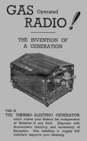 |
| Left: The gas-fired thermo-electric generator: 1930s.
Well, it was certainly the invention of a generation, but not of the generation that advertised this machine, as you will have seen from the thermopiles above.
It is believed it contained thermopiles (ie series arrays of thermocouples) that produced 2 Volts @ 0.5 amps for valve filaments/heaters and 120 Volts @ 10mA for the HT.
Thermocouples do not generate much voltage, but since they are simply junctions between two kinds of wire, connecting many in series is feasible. One of the most useful combinations is Ni/NiCr, ie nickel/nickel-chromium. This has a thermovoltage of about 4 mV/100K and a usable temperature range up to some 1000 K. This is very likely the type of couple used in this generator; it implies that 40 mV is about the most you can get from each thermocouple, so 50 in series would have been needed for the 2 V filament supply and 3000 in series for the 120 V HT. This sounds possible, though probably rather protracted to assemble and maybe heavy on labour costs. It would be interesting to know what the retail price was.
Picture kindly provided by John Howell.
|
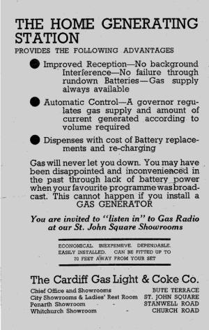 |
| Left: Advertising blurb for the thermo-electric generator. Probably printed on the other side of the page above.
The automatic control feature is intriguing. Given that any radio of the time would have had a Class-A output stage, whose current drain does not depend on volume, there seems no need to compensate for load changes. What might have been more useful (and possibly what the copywriter meant) would have been control to stabilise the 2V filament supply against changes in gas pressure. Excess filament voltage would have seriously reduced the life of the valves.
You may have heard of "steam radio" but this advertisment offers "gas radio".
Picture kindly provided by John Howell.
|
HENRY MILNES AND HIS GAS RADIOS
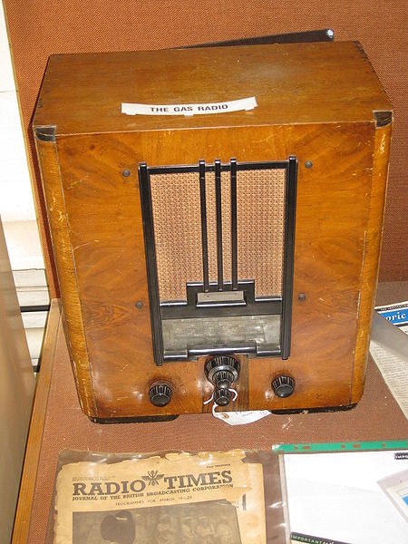 |
| Left: Gas-powered radio set made by Henry Milnes of Yorkshire: circa 1938. The Milnes Radio Co Ltd traded from Church Street, Bingley.
This is a complete radio set with a internal thermoelectric generator, built by the Milnes Electrical Engineering Company. One source states that the thermoelectric generator was in a lower compartment lined with asbestos, with the electronics and speaker in the top section. This does not match the appearance of this model.
The high tension supply as well as the filament power was provided by the thermopile; it powered the Milnes HT converter, which was probably a vibrator and transformer system; it produced 120V. The burners were ignited by flash device operated by the volume control knob.
The sets sold for Ł15, when Ł5 was a good weekly wage. It was claimed out that the running costs were half that of rechargeable accumulators. It was also pointed out that the radio would help to warm the house- which is fine in winter but you might want to listen to the radio in the summer.
At any rate, they did not succeed. A retired salesman told Historic Gas Times that he had had gas radios in his showroom but had only ever sold one of them.
The model seen here is in the National Gas Museum, Leicester, England.
|
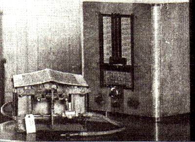 |
| Left: The Milnes gas-fired radio: circa 1938
The thermoelectric generator is on the left, and a Milnes gas radio on the right.
With no sign of a connection for an outside flue, I can't help wondering how much carbon monoxide these things produced. A flame playing on a cooler piece of metal (which is exactly how these generators were constructed) is the classic way for carbon monoxide to be produced.
This picture is also believed to be from the National Gas Museum, Leicester, England. Apologies for poor picture quality.
|
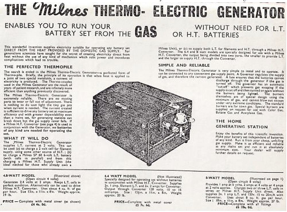 |
| Left: The Milnes gas-fired thermo-electric generator: circa 1938
This advert gives a good deal more information, though the text is only just readable.
Henry Milnes emigrated to New Zealand in the 1950s, complaining that government bureaucracy was interfering with his business.
|
The details of the three models advertised are as follows:
- 4.8W model. 2.4V at 1A for LT. 4 cu ft of gas per hour. Weight 15 pounds
- 6.4W model. something V at 1A for LT. Something V at 1A for the HT converter. Weight 20 pounds
- 8W model. 4V at 1A or 4V at 2A or 1V at 4A. Also 2V at 1A for LT and something at something for the HT converter. Weight 27 pounds
I am aware the wattages don't match up, but that's what the ad says. Unfortunately some figures are not quite legible.
THE RUSSIAN LAMP: 1959
The Russian Lamp is probably the best-known of all thermo-electric generators.
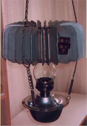 |
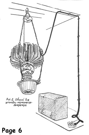
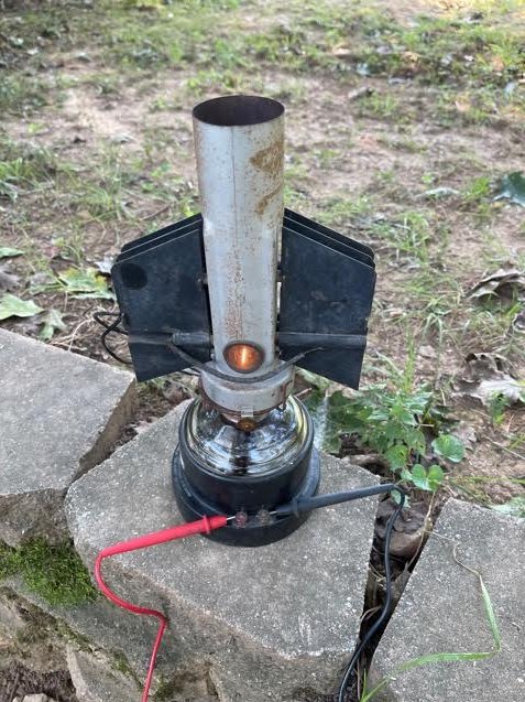
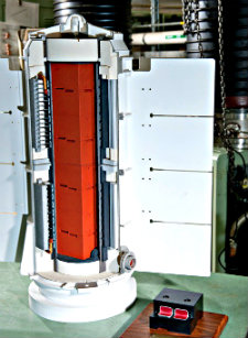
| Left: A Russian thermo-electric generator based on a kerosene lamp.
This lamp was introduced in 1959, once again to power radios. Presumably there were parts of Russia that Stalin's electrification program had not reached. According to Popular Mechanics for May 1959, the lamps were also exported to India. The thermoelectric elements comprised a zinc-antimony semiconductor (ZnSb) with constantan as the other element.
I have been informed by Pine Pienaar that he has seen one of these things, and it yielded both 1.5 and 90 Volts, so it could replace a composite dry battery with the same output voltages. Such batteries were once widely used to operate small portable valve radios.
Such radios typically used four 7-pin valves and needed a 90V HT supply at around 12mA and a 1.5V filament supply at 125mA or 250mA depending on the valves used.
This example seems to be missing its metal chimney. (see pictures below)
|
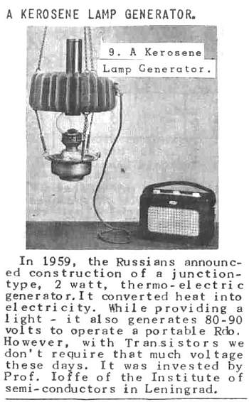 |
| Left: Cutting about the Russian thermo-electric generator
Abram I Ioffe, a Russian physicist, wrote a book in 1929 called "Semiconductor Thermoelectric Cooling" that demonstrated that semiconductor thermoelectric materials could be more efficient than metallic thermocouples. The book has been called "The Bible of Thermoelectric Semiconductors". Dr Ioffe's zinc-antimony/constantan elements gave an efficiency of 2 to 4 %, compared to less than 0.1% for metallic thermocouples, and made the lamp a practical proposition. (No doubt "invested" should read "invented")
The first thermoelectric generators produced low voltages only, and a vibrator power supply was required to get HT for valve equipment.
Cutting kindly provided by Ed Maurus, original source unknown.
|
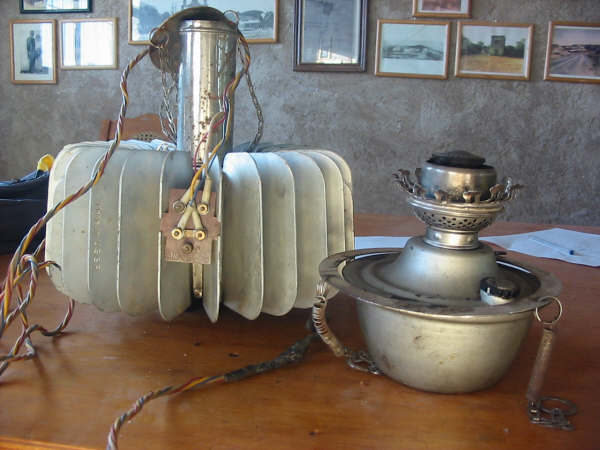 |
| Left: Russian thermo-electric lamp partly dismantled
Pablo Reyes tells me that there are thirty cooling fins. The terminal plate has 5 terminals, duly numbered 1 to 5. See the diagram below for their function.
Photo kindly provided by Pablo Reyes
|
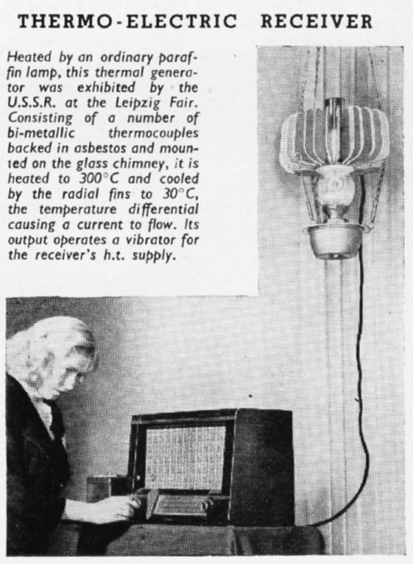 |
| Left: Russian thermo-electric lamp at an exhibition in Leipzig in 1956
Leipzig was in Soviet-controlled East Germany, which may account for the lady's anxious expression. Still, at least Stalin had died in 1953.
The reference to a vibrator HT supply was erroneous guesswork on the part of the caption author. All accounts agree that there was a direct 90V HT output, which is quite enough for battery-type valves.
(In this context a 'vibrator' is an electromechanical device, similiar to an electric bell, that chops low-voltage DC into crude AC that can be applied to a step-up transformer. They were widely used in car radios before semiconductors arrived. Vibrators were noisy and unreliable devices and avoided wherever possible)
Here we actually get some working temperatures. Another source says that the thermal elements were heated to 570 degrees by the flame while the fins cooled their other side down to 90 degrees, but this appears to be simply a conversion of the Centigrade values to Fahrenheit. That source also says that the lamp worked best by an open window, so that air currents could cool the fins more effectively. Not so good in a Russian winter...
Pity about the asbestos but its dangers were not appreciated at that time.
The radio is a Soviet Rodina 52 model. (more on that below)
From Wireless World May 1956 p227
|
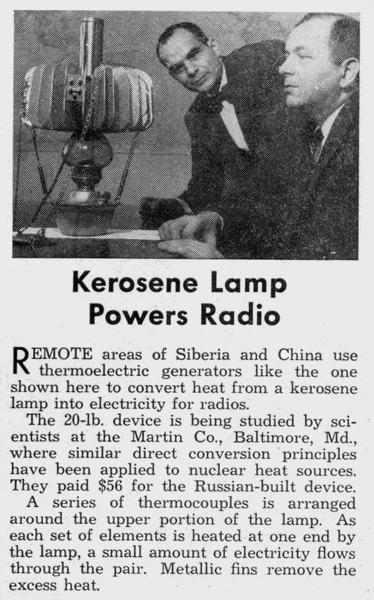 |
| Left: American scientists study a Russian thermo-electric lamp in 1960
At 20 pounds that is one heavy lamp, and $56 was a lot of money in 1960.
The lamp actually used semiconductor thermojunctions rather than metallic thermocouples.
From Science & Mechanics June 1960
|
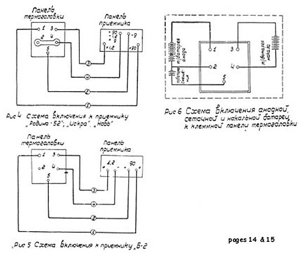 |
| Left: Wiring diagram for connecting the lamp to radios
Here we learn for the first time that there were actually three output voltages; +90V for the HT, +1.2V for the valve filaments, and -9V, presumably for valve biasing. It looks as if you get a floating 1.2V supply between terminals 3 and 4, with terminal 3 positive. The 90V HT supply is isolated from that and appears between terminals 1 and 2, with terminal 1 positive. The 9V bias supply appears between terminals 2 and 5, with terminal 5 at -9V.
The diagram at top left shows the connections for a radio that requires a separate bias supply (I think that even in 1959 that would have been considered old-fashioned) with the HT and LT 0V terminals strapped together.
From the lamp instruction manual
|
The diagram at lower left shows the connections for a radio that does not require a separate bias supply. It looks as though the HT supply is being taken from terminals 1 and 5, which gives an HT of 99V. (Although '90V' is written on the radio end) Presumably this would give better operation than 90V, providing of course that the radio was built to cope with it. The diagram at top right appears to be the equivalent circuit of the lamp.
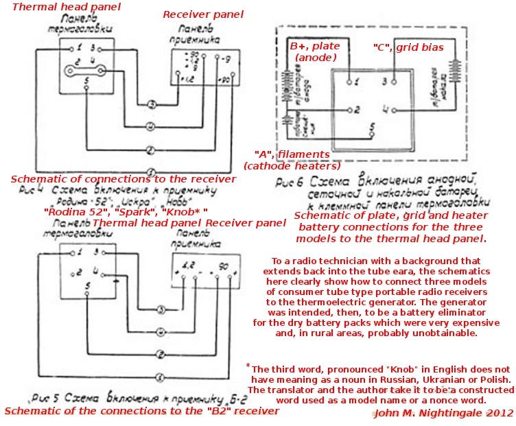 |
| Left: Translation of the lamp diagram
I am very grateful to John Nightingale and and his colleague for this translation of the text on the diagram.
Note that the lamp and its thermo-electric elements is refered to as the "thermal head".
Pavel Panenka tells me that the receivers named here translate as follows: Rodina 52 (= Homeland 52), Iskra (=
Spark) and Nov' (the fourth character being "soft sign"), meaning Novelty or Innovation. In the Russian alphabet the character "b" reads as "v".
|
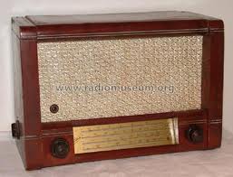 |
| Left: A Rodina 52 Russian radio
This is the radio being anxiously tuned in by the lady above.
It was a 7-valve superhet, with a heptode oscillator/mixer followed by two IF stages. There were four more valves in the push-pull audio output stage, though the output was only 150 mW. All were single section valves, so seven were required. Their cathodes were all directly-heated and wired in parallel.
|
 |
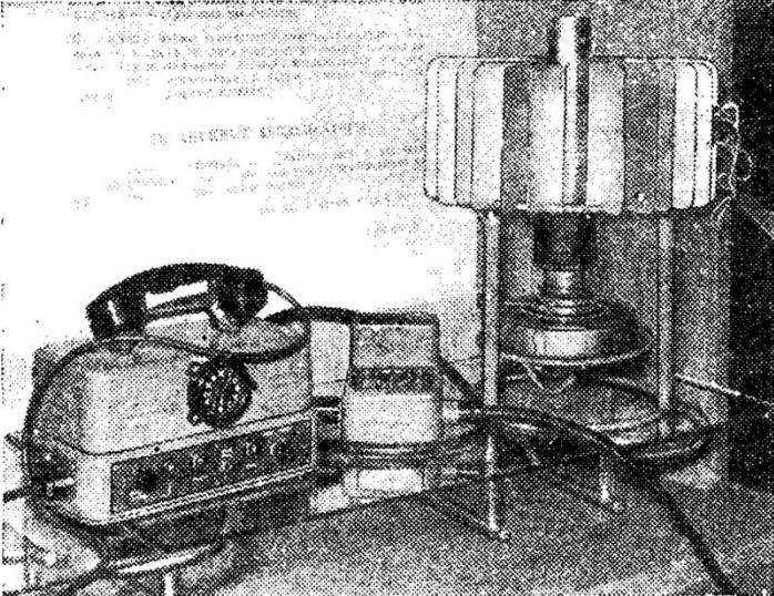
| Left: Russian drawing of the lamp in use
Either the lamp is swinging around wildly, or something has gone badly wrong with the perspective.
That looks like a Rodina 52 radio again.
|
 |
| Left: Russian TGK-10
A low-voltage only generator, the TGK-10 was produced. This version did not double as a lamp; its somewhat higher power output of 10-12 Watts, was intended for storage battery charging. The battery in turn powered a vibrator supply. It is shown here powering a "Harvest-1" low power, 2-3 MHz AM radio telephone, as used on large collective farms.
Thanks to Robert Lozier for providing this image
|
THE 3M AZTEC-12 GENERATOR LAMP: 1959?
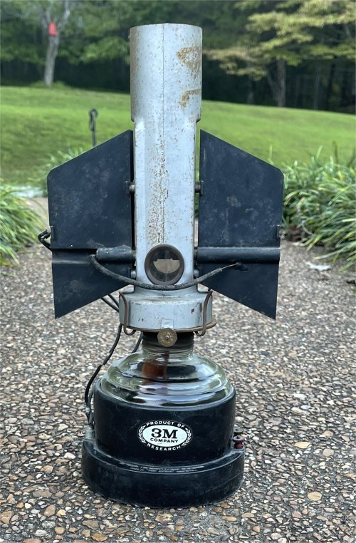 |
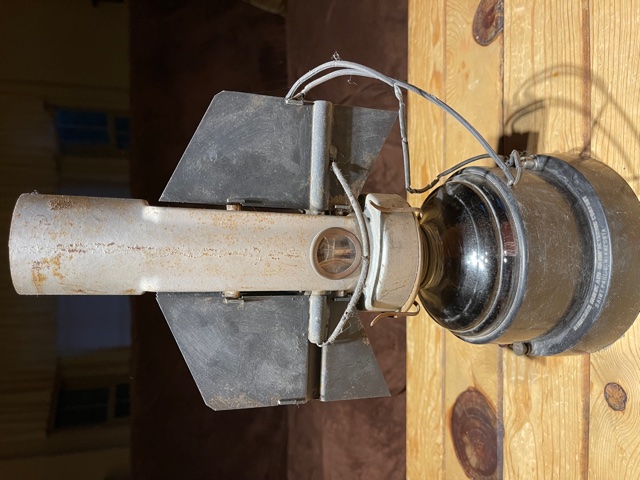
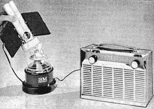
| Left: The Aztec-12 thermo-electric generator from 3M: 1959?
This thermo-electric generator was built by the Minnesota Mining & Mfg. Co., otherwise known as 3M. Given the small size of the window in the chimney, it does not seem intended to work as a lamp as well. The thermocouple elements (presumably multi-junction) are horizontal with one end in the flame and the other attached to a black cooling fin; note that the fins are identical to simplify manufacture.
These pictures ere kindly provided by Joseph Frank, who once owned it. He fired it up and it duly generated electricity.
There is another example in the Canadian Ingenium museum. In their description they say "It represents the US (CIA) response to the famous Russian oil lamp thermoelectric generator widely used in Asia (Russia & China) to power home radios." This seems like a wild bit of speculation; why would the CIA be interested in powering farmer's radios? In some post-Soviet-invasion scenario, perhaps?
The museum description states: "Metal base, chimney & component pieces. Glass top on fuel reservoir. Mica windows in chimney." They say very few were made, but their example has the serial number 224. They give dimensions of 24.0 cm high by 14.0 cm wide.
|
 |
| Left: The Aztec-12 thermo-electric generator from 3M: 1959?
The information below comes from the Canadian Ingenium museum.
|
|
'3M COMPANY' appears in large white print on decal on base front. Cast in raised print, below: '3M brand thermoelectric generator Model 12 'The Aztec' made in U.S.A.'. On opposite side of base, cast in raised print is: 'Minnesota Mining and Manufacturing company, Saint Paul 6, Minnesota'.
Label on underside of base reads: '3M brand thermoelectric generator, Model No.12 "The Aztec"/ voltage range 3 to 9V DC. Nominal power output 100 mW. Patented under one or more of the/ following US Patents: 2,790,021 2,811,440 2,811,441 2,811,569 2,811,570 2,811,571; other patents pending'
Minnesota Mining and Manufacturing company, Saint Paul 6, Minnesota. 'Eagle' appears in raised print on wick cover. 224 incised on chimney base, P & A. Mfg. Co. Thomaston, Conn. Made in U.S.A.'
Incised on wick adjustment knob "Underwriters' Lab". Label on wire connecting chimney to base present but illegible. Cardboard box marked '3M company' on 2 sides, in green ink on 3rd side box printed 'From 3M company, ship to, return requested'. 'This side up' printed in green ink on box lid. 'Aztec' handwritten in black ink on lid. 'â?4d+/ b374/ 4' handwritten on box, 3M mailing, railway express agency receipt, customs and export labels affixed to box.
|
|
That settles the output voltage question, though a wide range of 3 to 9V doesn't sound very useful.
|
 |
| Left: The Aztec-12 thermo-electric generator from 3M: 1959?
This picture shows the generator lit and producing electricity. The red and black cables run to a digital multimeter. The highest voltage measured in this run was 1.31V; this was reportedly with a low flame setting. It is nearly twice the voltage quoted below; there seems to be some uncertainty here.
In this picture it can be seen that there are three fins on each side.
|
 |
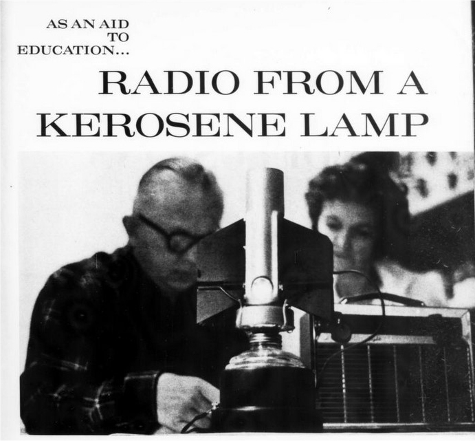
| Left: The Aztec-12 thermo-electric generator from 3M: 1961
This picture appeared in "Radio & Hobbies" in August 1961. The picture is of poor quality, but it appears that the lamp is lit and about to power an early transistor radio. The article says the generator "is envisaged as an alternative method of powering radios in emergencies which might arise from atomic war" so maybe the CIA were involved.
It is perfectly possible to power a transistor radio from 9 Volts, and this probably explains the low output voltage, which would simplify the construction. (fewer thermocouples needed) Transistor radios must have been assumed in the design from the start, as they consume very little power compared with a valve radio.
|
 |
| Left: The Aztec-12 thermo-electric generator from 3M: 1961
This picture shows the same transistor radio as the image just above.
Source: Look magazine Dec 1961 p115. Images courtesy of Brent Rowell.
|
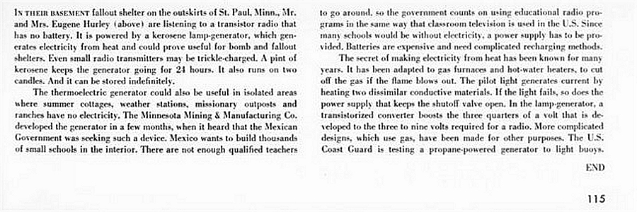 |
| Left: The Aztec-12 thermo-electric generator from 3M: 1961
The text tells us that the intended use was in fallout shelters post-apocalypse, and various sites without mains electricity. Be aware that the first transistor radios appeared in the period 1954-57 and so a transistor radio at this date is not at all anachronistic. Note the transistor converter required to raise the 0.7 Volt thermocouple output to 3 to 9 Volts (why the wide range?) for a transistor radio.
Source: Look magazine Dec 1961 p115. Images courtesy of Brent Rowell.
|
The Mexican connection was probably the reason for the 'Aztec' name. The Aztecs flourished in central Mexico from 1300 to 1521.
THERMO-ELECTRIC GENERATORS TODAY
These machines are alive and well, being used in remote places where small amounts of electricity are required and the complications of an internal-combustion engine and alternator are not welcome. Modern versions use a thermopile made up of a series array of lead-tin-telluride semiconductor elements, rather than simple thermocouples. These thermojunctions are much more efficient than simple thermocouples, and have been available since the mid-1960s. They are commonly used (working in reverse, of course) to cool the little sofa-side beer refrigerators which are now quite common. The modern generators supply electricity to satellites, space probes, navigational aids, communication systems, safety equipment for offshore installations, and for the cathodic protection of gas pipelines.
This gives a very good account of semiconductor thermojunctions and how they work: Thermoelectrics by Tellurex (external link)
For one example of modern gas-fired thermoelectric generation, see: Global Thermoelectric. (external link)
Thermoelectric generators can also be heated by radioactive decay, and such devices are used to power interplanetary space probes and the like, where distance from the sun means that solar power is not an option. See:
Free Dictionary: RTGs
Even so, I was thinking that thermoelectric generators must be very rare- and then I found one working away in my garden shed. They are everywhere around us!
They are used in central heating boilers to control the pilot-light valve. When the pilot is burning, the thermopile generates about 750 mV- enough to actuate a small solenoid that keeps the pilot valve open. This sadly doesn't mean you can run a central-heating system with no electric power, as the main gas valve is operated by mains power switched by the room thermostat; in any case, the pump wouldn't run.
Today, the most popular thermoelectric material is bismuth telluride, though its main use is in Peltier cooling rather than power generation.The maximum operating temperature for this material is 550-600K, so it can also be used to generate electricity.
Materials based on alloys of lead are used in the intermediate temperature range. (about 900K) The high temperature range is occupied by the Silicon-Germanium (SiGe) Alloys. They can operate at temperatures up to 1300K. The two latter materials are used in the radioisotope generators.
There is some fascinating info on experimental thermoelectric stoves
here.
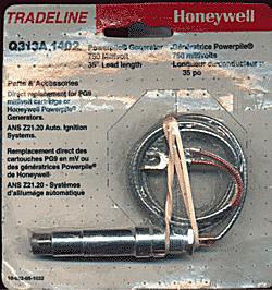 |
| Left: A modern thermo-electric generator or thermopile made by Honeywell for boiler control.
The voltage output is 750 mV with the "Cold" Junction at 416 degC (780 F) and the Hot Junction at 760 degC. (1400 F) I know that 416 degC is not exactly cold, but this thing is mounted inside the boiler combustion chamber.
Assuming Ni/NiCr thermocouples are used, we can deduce from this that the device contains about 55 thermocouples in series.
So why is a thermopile used for this job? Presumably because it is very simple and reliable; it is hard to see how a thermopile could fail to the danger state- it can hardly generate electricity when it isn't hot, and either a short-circuit or an open circuit would stop the flow of electricity to the valve solenoid.
|
THE BIOLITE STOVE
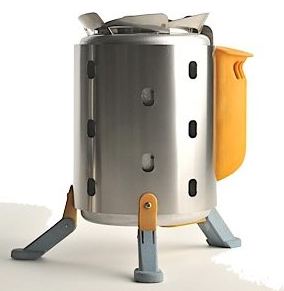 |
| Left: Biolite thermoelectric camping stove
This ingenious stove burns small sticks of wood or similar fuel. As the fire warms up, a thermoelectric generator starts to drive a small fan, intensifying the combustion. (and presumably also cooling the cold end of the thermojunctions) It can then boil a litre of water in four minutes. The stove is 7.5in tall and 4.75in diameter, and weighs 1lb 10oz.
Enough surplus electricity (about 1-2 Watts) is generated for running LED lights or charging mobile phones. You can see their website here.
|
 |
| Left: Biolites charging mobile phones after Hurricane Sandy: 2012
And also heating up some food at the back there.
The design of the legs seems to have changed.
|
THE LUFO LAMP
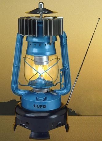 |
| Left: Lufo lamp with radio: 2013
The Lufo Lamp is a hurricane lamp with an AM/FM radio built into the base. Apparently all you can do with it is listen to the radio (an AM/FM radio can be run on very little power) and charging your phone etc is not an option. Whoever wrote the URL seems to think its some sort of heat-pump, whereas it is the opposite; generating electricity by letting heat flow downhill.
|
THE CURIOSITY MARS ROVER RADIOISOTOPE THERMOELECTRIC GENERATOR (RTG)
 |
| Left: The Curiosity RTG (NASA picture)
Right now the most important RTG in the solar system is the RTG that powers the Curiosity Mars rover. Solar cells do not work well on Mars, as they cannot function in either the Martian night or the Martian winter. Curiosity is therefore kept rolling by an RTG that contains some 5 kg (10 pounds) of plutonium-238. (not the plutonium-235 used in atom bombs) It is designed to power Curiosity for at least 14 years. The elecrical output is 125W at the start of mission; that will slowly fall to about 100W after 14 years. The initial thermal output is 2 kW. so the efficiency is still only 6% for what is presumably one of the most advanced RTGs in existence.
NASA call it the Multi-Mission Radioisotope Thermoelectric Generator, or MMRTG. In pictures of Curiosity the RTG can be seen as a hefty black cylinder sticking out of the back like a tail.
It has its very own own Wikipedia page.
|
THE CASSINI-HUYGENS MISSION RADIOISOTOPE THERMOELECTRIC GENERATOR (RTG)
The Cassini-Huygens mission was a robotic probe sent to study Saturn, its rings and natural satellites. The spacecraft was launched in 1997. It was made up of the NASA Cassini probe, and the ESA Huygens vehicle which landed on Titan, Saturn's largest moon. Since the sunlight is feeble that far out, a solar-cell array would have been too large and too heavy to be practicable. Cassini-Huygens was therefore powered by three plutonium-fuelled RTGs.
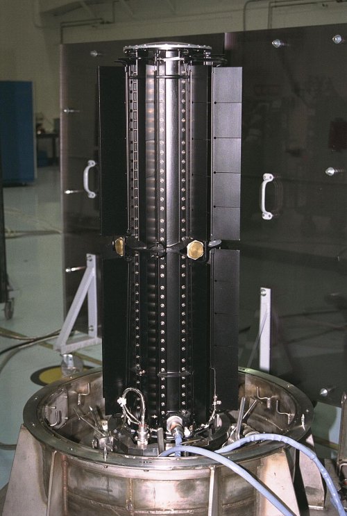 |
| Left: One of the three RTGs for the Cassini-Huygens mission
The Wikipedia article on the Cassini mission has a whole section devoted to the plutonium power source.
The specific design of RTH is the GPHS-RTG (General Purpose Heat Source — Radioisotope Thermoelectric Generator) which was also used on the Ulysses and Galileo missions. Each GPHS-RTG weighs 57 kg and generates about 300 Watts of electricity at start of mission, derived from 4,400 Watts of heat output from about 7.8 kg of Plutonium-238, in the form of its oxide. Plutonium-238 is a very powerful alpha-emitter and a sample will glow red-hot from its self-heating.
Note that even with a sophisticated design such as this, the energy conversion efficiency is only 6.8%.
On 15th September 2017, the Cassini spacecraft was deliberately destroyed by sending it into Saturn's atmosphere. This was done because it is
considered imperative to prevent biological contamination of any of the moons of Saturn which might harbour life. Cassini was active for twenty years.
Image courtesy of Applied Thermoelectric Solutions LLC.
|
MISCELLANEOUS
 |
| Left: Advert in Popular Mechanics: date unknown
The price seems quite reasonable...
|
THERMOPILE LITERATURE
Not a great deal seems to have been written on thermopiles. The best reference I have found is in Volume 4 of "Electrical Installations" by Rankin Kennedy, who was not a rastafarian. (Caxton Publishing Co., London 1903) p105-117. Rankin Kennedy (c1854-1917) was a consulting engineer (electrical), an inventor and a prolific author. For biographical details, see his obituary in The Engineer for 27 April, 1917.


