Updated: 10 Oct 2011
More info, new pic added


The Still Steam-Diesel Engine |
Updated: 10 Oct 2011 |
|
|
From the beginning there was controversy as to whether the greater efficiency and load-handling capacity was enough to justify the extra complexity. Such records as survive indicate that despite undisputably high efficiency the engines of the Dolius were intensely disliked by the engine-room staff as being over-complex and unreliable. Any fault with the steam side was likely to affect the diesel side, and vice-versa.
 | Left: This is a conceptual diagram of the Still system.
|
Steam is taken from the top boiler drum at D and fed to the steam cylinder. The exhaust E from the steam cylinder powers a low-pressure turbine F, which drives the Diesel scavenge blower G of the diesel engine. The electric motor M is needed as part loads do not generate enough steam to drive the turbine; this could also be used as a generator when there was plenty of steam. The engine back-pressure was 19 in Hg vacuum, and the turbine exit vacuum 29 in Hg. I is probably some sort of jet condenser, with J either its injection pump or its air pump.
Various unique advantages were claimed for the shared-cylinder Scott-Still engine:
1) There is no heat loss caused by condensation of the admitted steam on the cylinder walls because they are preheated by the previous diesel combustion stroke.
2) The piston is kept from overheating by the presence of the relatively cool steam on its underside.
Two four-cylinder Scott-Still engines were installed on the Dolius. The steam cylinders had some sort of hydraulic valvegear, the details of which are currently obscure. The steam side was effectively triple-expansion; the aftmost steam cylinder was a high-pressure cylinder, the remaining three being run at intermediate pressure. Final LP expansion was done in the turbine driving the the scavenge blower. Overall efficiency was claimed as 38%, with 14% of the power coming from the steam side. That 14% involved a lot complication. Engine speed was 120 rpm.
The Dolius was lost during the Second World War; in 1943 she was torpedoed and sunk in the Gulf of St. Lawrence, Canada.
A second vessel was fitted with Scott-Still engines; the twin-screw cargo liner Eurybates built in 1928, and also part of the Blue Funnel line. The engines were more powerful than those of the Dolius, now giving 2500 bhp per shaft at 105 rpm, and had been drastically redesigned. The six forward cylinders were conventional two-stroke single-acting diesel units, of 17 in diameter by 45 in stroke, and the two aft cylinders constituted almost an independent steam engine, using Marshall valvegear and piston valves. This radical change appears to have been made to prevent oil from the diesel section of the engine from contaminating the boiler feedwater.
The steam cylinders were only converted to Diesel in 1948, so the principle must have been workable.
If anyone cares, Dolius and Eurybates are minor characters in Homer's Odyssey.
 | Left: The engine-room arrangements of the Dolius.
|
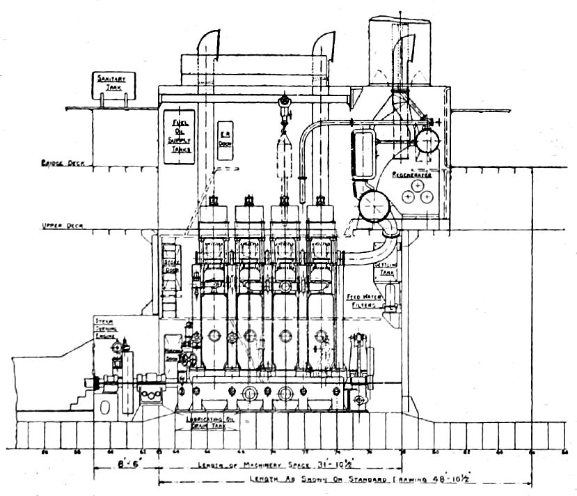 | |
Above: Drawing of a Scott-Still engine-room arrangement for a single-screw cargo-vessel.
|
 | Left: This intriguing diagram shows the comparative efficiencies of steam and IC engines in 1920.
|
The information below was kindly provided by Brian Dickson. I have edited it slightly. He writes:
"I served with the company concerned (Blue Funnel), but after those ships had gone, and my knowledge comes with talking to senior engineers who had served on them.
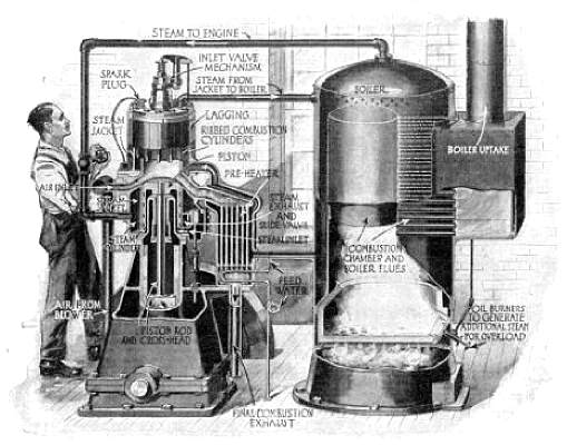
"The Scott-Still marine engines were of two designs, the first with diesel on the top of the piston,and steam on the underside of the piston, as illustrated; this was the approach used in the Kitson-Still locomotive. The second version had diesel power on five cylinders, and then two conventional steam cylinders on the same crankshaft providing power from the exhaust-heated boiler.
"The first design (fitted in the Dolius) suffered from the basic flaw of cross-contamination. Oil from the diesel part of the engine contaminated the boiler feedwater, (this seriously cuts down heat transmission in the boiler), and water contaminated the lubricating oil in the diesel engine crankcase.
"It was the second type of engine that was fitted in the Eurybates, and this avoided the cross-contamination problems as the steam cylinders were segregated from their diesel counterparts. It also meant that the two steam cylinders concerned could be, (and were) replaced by conventional diesel cylinders when other economic factors dictated it.
"These vessels required dual qualified senior engineering officers (Steam and Motor certificated), whereas conventional steam vessels only required Steam officers, and conventional Diesel motor vessels only required Motor officers. The career path of dual qualified officers, once qualified, was usually to quit seagoing, and go into survey\classification employment ashore.
"Thus, although they were a revolutionary concept, efficiency-wise, these engines exacted personnel and maintenance problems which offset the economy."
 | Left: An excerpt from "Modern Motor Cars and Commercial Vehicles" by Arthur W Judge
|
EXHAUST GAS BOILERS
The desire to make use of the heat in diesel exhaust gases did not disappear with the Still reciprocating system. As engines grew larger the amount of heat available increased until it could generate enough steam to run a turbo-alternator that provided all the electrical power required in the ship, with a surplus for heating purposes. The exhaust gases of modern Diesel engines contain thermal energy equivalent to more than 30% of the total heating value of the fuel. The temperatures of the exhaust gases vary from 270°C to 320°C for slow two stroke engines, and from 350°C to 480°C for medium speed four stroke engines. Modern engines have increased in efficiency to the point where the exhaust heat available is reduced, and enough electricity can now only be generated by relatively sophisticated steam-generating systems.
 | Left: This is a modern exhaust boiler system
|
FURTHER READING
For more on the Scott-Still System see Marine Diesel Engines: Scott (External link)
The Still system was also applied to locomotives on several occasions. See also The Kitson-Still Locomotive and Russian Reforms.
Bibliography: Scientific American, May 1927

|