The steam boiler as a means of generating static elecricity is not an obvious concept. It was developed by William George Armstrong, (1810-1900) allegedly as a consequence of an incident with a colliery boiler: "A mechanic was busy repairing a steam-engine near Newcastle, having one hand in a jet of steam that was escaping from a leak, with the other hand on the lever of the safety valve; he drew a brilliant spark and received a violent shock. Armstrong studied the conditions of the phenomenon, which is known as the Armstrong Effect."
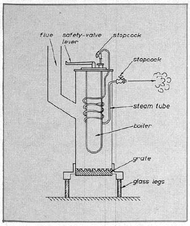 |
| Left: The first Armstrong electrostatic boiler: 1841
On hearing of the effect, Armstrong began a series of investigations. This is his first experimental boiler of 1841, which he called his 'evaporating apparatus'; water boils in the inner vessel, and is then superheated in the coiled pipe exposed to the fire, before exiting to the atmosphere via the stopcock.
Superheating, while worthwhile in locomotive boilers, would appear to be the last thing wanted here, where wet steam was found by Faraday (see below) to be essential for generating electricity.
The first boiler was 30 inches high and four inches in diameter, mounted on glass legs. By the end of 1842 he had built larger version of wrought-iron, with rounded ends, (to more efficiently withstand steam pressure) 3.5 feet long and 1.5 feet in diameter. This was still externally fired.
No picture of an Armstrong boiler that I have seen has rounded ends, and it is possible no image of this version exists.
|
The quoted details here are taken from "Electricity and Magnetism" edited by Silvanus P Thompson, pub Macmillan 1891.
"There was one at the Royal Polytechnic Institution in London with forty-six jets, and which gave sparks two feet long; it was a fearsome machine, making a deafening noise, and producing 22-inch (560 mm) sparks; it knocked out a man who got too close and killed a large Newfoundland dog. (I hope the latter was not deliberate, but I suspect it was) The electrical breakdown strength of air at sea level is about 30 kV/cm, so that represents 1,680 kV. Over a million volts!
The Polytechnic boiler was 6.5 feet long and 3.5 feet in diameter It was constructed under Armstrong's supervision, aided by the lecturer in natural philosophy, Dr Bachoffner; he does not have a Wikipedia page. However it is described in Noad`s Electricity, and quoted by Pepper as being a cylinder boiler of 5/8inch boiler plate, 7 feet 6 inches long (2metres approximately) by 3 feet 6 inches diameter. (about 1 metre) Its glass legs were 3.5 inches diameter and 3 feet high. Steam pressure was 60 lbs per square inch and spark-length 22 inches. No photograph of this machine is known to exist, and yes, I did google it in French.
An even more impressive-sounding machine lived at the Sorbonne university in Paris; it had had eighty jets, and gave sparks several inches in length. It sounds like there was some sort of arms race going on there; eighty jets sounds fearsome but I think a spark of '22 inches' probably beats 'several inches'. No image at all of this machine has so far been found; a great pity.
Investigations by Michael Faraday proved that escaping was steam was not sufficient to generate electricity; it had to be wet steam, partially condensed and so carrying water droplets with it. Armstrong's boiler therefore had a rectangular box cooled by water, through which the steam-pipes passed on the way to the nozzles, in order to produce some condensation. The theory was that the water droplets became electrically charged due to friction with the wooden walls of the boxwood nozzles; however it appears that even today there is no consensus on the exact mechanism. This is not just an academic question as in 1969, three large oil tankers were sunk or damaged by explosions thought to be caused by sparks from electrically charged mist during tank washing with jets of hot and cold water or steam See here (External link)
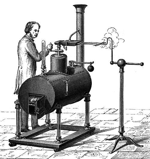 |
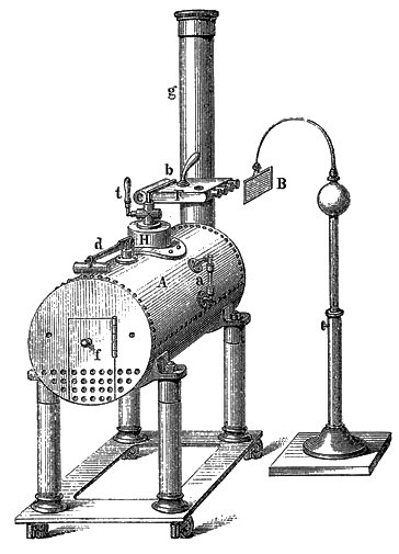
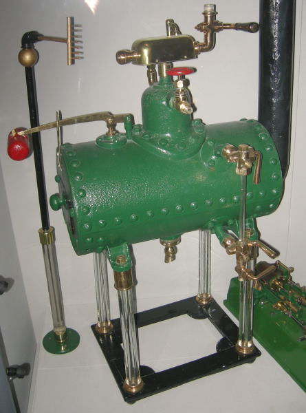
| Left: The Armstrong Electrostatic Boiler
The boiler is insulated from ground by four glass legs. Steam jets escape from boxwood nozzles on the rectangular cooler box. The stand to the right, apparently incorporating a glass column, collects the electric charge by a series of sharp metal points held opposite the jets. This version appears to have three nozzles.
Going from left to right along the top of the boiler, can be seen the pressure-gauge (which appears to be some sort of mercury manometer) the steam-dome and control-valve, with the cooler box on top, and a lever-type weighted safety-valve. On the side of the boiler is a water-gauge of the usual sort.
The small curved pipe running from the cooler box to the chimney is of unknown function; very probably it carried away steam evolved from the cooling water.
The operator appears to be adjusting the steam-valve; how he could do this without getting a severe shock is not clear. Even if the valve handle was insulated, this would not stop a voltage that could throw two-foot sparks.
One wonders if the square-jawed chap at the valve is supposed to be Armstrong himself: see portrait below.
You can see an Armstrong boiler (a modern replica) in action on YouTube. The first spark is at 1:28.
|
Part of a lecture by Lord Armstrong on the hundredth anniversary of the Literary and Philosophical Society of Newcastle-on-Tyne:
"..Probably many of you are aware that soon after I introduced my hydro-electric [steam electrostatic] machine I designed and made a very large one for the Polytechnic Institution which then existed in London. It proved to be by far the most powerful instrument for the production of frictional electricity that had ever been seen."
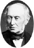 |
| Left: William George Armstrong: about 1870
|
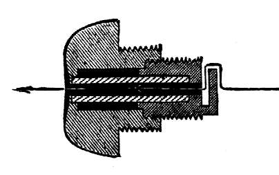 |
| Left: One of the boxwood nozzles in section
Note the deliberately indirect steam path. This was designed to increase the friction as the steam passed through the nozzle.
Boxwood is a hard, fine-grained wood, and was presumably selected as being resistant to erosion by the steam.
|
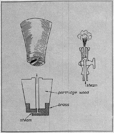 |
| Left: Another picture of a nozzle in section
As with the illustration above, the steam has to traverse two right-angles, and this will generate turbulence and increased friction.
This illustration shows partridge wood instead of boxwood; they are different species. Partridge wood is tough, strong and has a high resistance to impact and abrasion.
|
 |
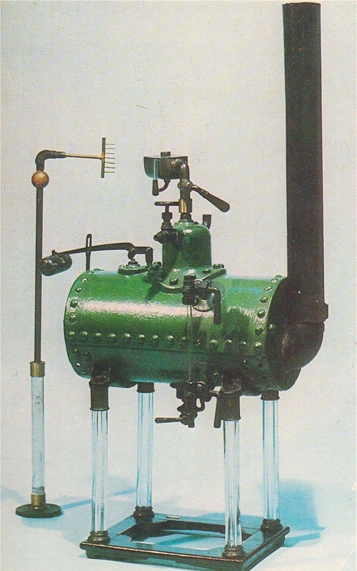
| Left: Another picture of an Armstrong boiler
Note the differences with the picture above. The steam dome is smaller, and the safety-valve is in a different position.
Once again there is a small pipe taking the steam evolved in the cooling box to the chimney.
It more closely resembles the Florence boiler shown below.
|
There is an Armstrong boiler in the Museum of The History of Science at Florence, one in the Science Museum (London) collection, and one at the Discovery Museum at Newcastle-upon-Tyne. There may be one at the l'�cole Polytechnique near Paris, but this is so far unconfirmed.
Unfortunately photography is not permitted in the Florence museum, so I am unable to show you the pictures below:
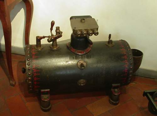 |
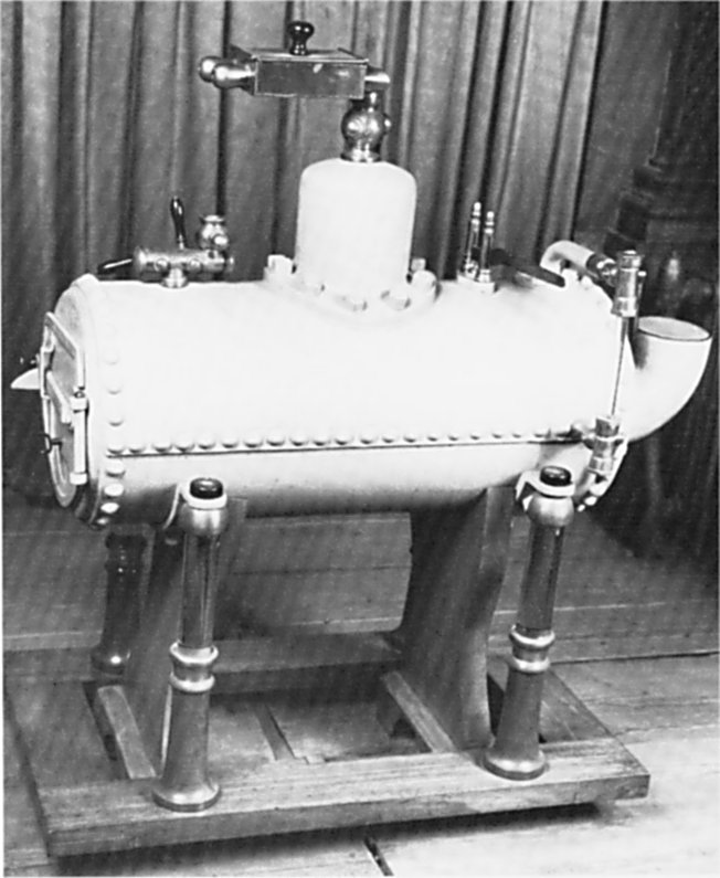
| Left: Armstrong Electrostatic Boiler at the Florence Science Museum: photograph 2005
This machine was made by Watkins & Hill of London, around 1845. It is missing a few parts, but otherwise closely resembles the contemporary drawing above. This one has four steam nozzles.
Missing are the four glass legs, the chimney, the safety-valve, and the pressure-gauge. The fittings for the water-gauge can be seen on the side of the boiler but the glass tube is missing.
The boiler is about a meter long. The museum gives its dimensions as 855 x 408 mm.
Author's photograph
|
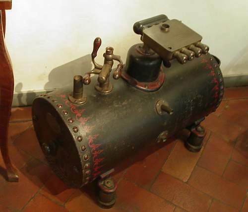 |
| Left: Armstrong Electrostatic Boiler at the Florence Science Museum: photgraph 2005
The Florence boiler has some kind of triple valve arrangement not shown in the drawing at the top of the page. Its function is unknown.
Author's photograph
|
 |
| Left: Armstrong Electrostatic Boiler
I have now identified this picture. It shows the state of the Florence boiler after the floods of 2007, and before restoration. The museum says it will never be placed on permanent display again, though I have no idea why not.
The pictures of it above were taken in Summer 2005 before the flood.
|
 |
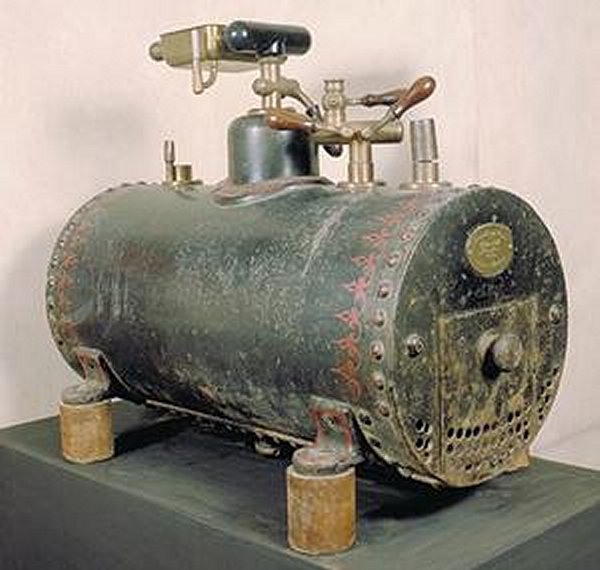
| Left: Armstrong Electrostatic Boiler
This Armstrong boiler is in the Discovery Museum at Newcastle-upon-Tyne, England.
This example looks complete, with water-gauge tube and safety valve (with red weight) installed, and glass legs present. At top left is the charge-collecting comb. Beneath the boiler can be seen the drain valve. No pressure gauge is visible.
Note there is a valve and steam outlet on the side of the steam dome. Its purpose is unknown, but it could have been used to run a small steam engine.
Possibly made by H Watson of Newcastle-upon-Tyne.
|
 |
| Left: Armstrong Electrostatic Boiler: built 18??
This is another picture Found On The Web. It appears to be the same machine as that just above, only without red paint on the safety-valve weight and steam-valve handle.
|
While the Armstrong boilers were considered to be the most powerful electrostatic machines of their day, there were problems. In operation they inevitably filled the room with steam, producing a humid environment hardly suitable for electrostatic experiments which depend on dryness to maintain insulation. This what Dr Bachoffner of the London Polytechnic had to say:
"The working of the machine is necessarily accompanied by the disengagement of an enormous quantity of steam, which, besides causing a deafening noise, has the mischievous effect of covering with moisture everything within reach. Accordingly, though very interesting in itself, it is by no means adapted to the general purposes of an electric machine."
One also wonders how the machine could be fuelled while in operation without giving the stoker a severe shock; possibly the boiler would be grounded while this was done.
The Armstrong boiler was not the only method of tackling the apparently paradoxical task of generating static electricity with water; another was Kelvin's Water Dropper. (which I think might well be calling out for a web page)
 |
| Left: Armstrong Electrostatic Boiler in the London Science Museum collection
This boiler also has the same kind of triple valve arrangement on the left top surface. Other details are different. Note the firedoor on the left and the flue on the right. The Science Museum say it was purchased in 1852 for Dfl 387. I think Dfl refers to Dutch guilders, which suggests it may have been of Dutch manufacture- or that it was bought by a Dutch institution.
The Science Museum has a much larger collection than it can show, and as far as I know this boiler is not currently exhibited.
|
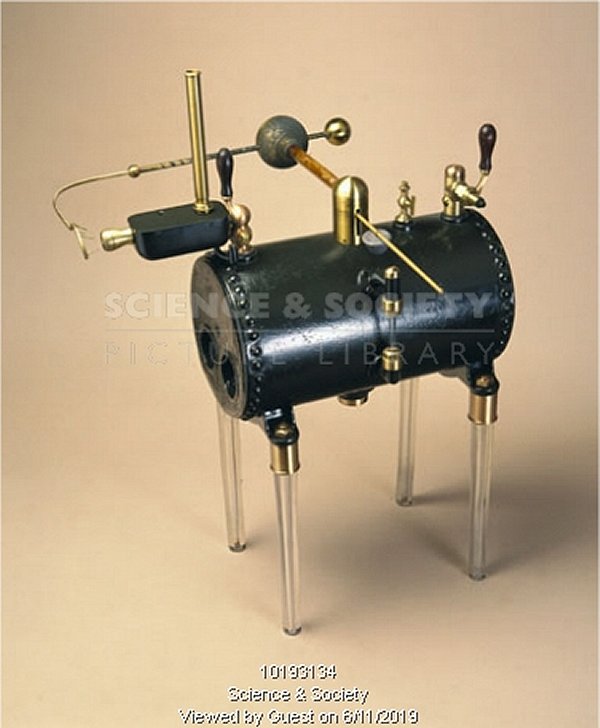 |
| Left: Armstrong Electrostatic Boiler: built 1845
This machine was presented to the British physicist Michael Faraday by Sir William Armstrong. Frustratingly, I have no dimensions, but it looks like a demonstration model, and I would guess the boiler is about 10 inches long. There is only one nozzle. It has a water-level gauge on the side, as with the larger versions.
what is not obvious is the safety-valve; perhaps the little brass thing to the right had that function, but it looks too small.
Inventory No: 1908-161
Source No: 1908-0161
Note the Science & Society copyright watermark. This is a preview image and as such is used in good faith for non-commercial purposes.
|
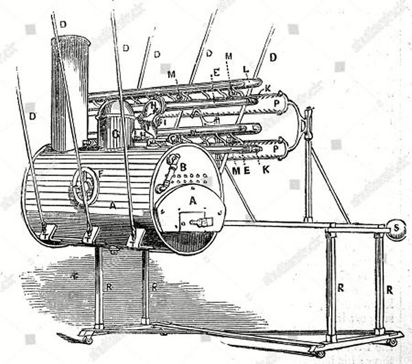 |
| Left: Unknown Electrostatic Boiler: built 18??
This image was found on the Web. It clearly represents an electrostatic boiler, but looks rather different from the Armstrong machines. The boiler is rather dramatically suspended in space by ropes; it is hard to believe this would be as effective an insulation as glass pillars.
Above and to the right of the boiler is an array of steam jets, and an array of collecting combs (labelled P) mounted on a wheeled trolley. Possibly it is a representation of the boiler at the Royal Polytechnic Institution in London, which had forty-six jets, but that is known to have stood on glass pillars. If anyone can offer any information I would be most grateful.
There is what looks a control wheel on the side of the boiler, labelled F; its function is unknown- perhaps steam flow was controlled by a valve inside the boiler. This was standard practice on steam locomotives, where the regulator valve was often mounted inside the steam dome.
From the filename, this appears to be a Shutterstock preview image and as such is used in good faith for non-commercial purposes. Attempts to track it down on Shutterstock lead nowhere.
|

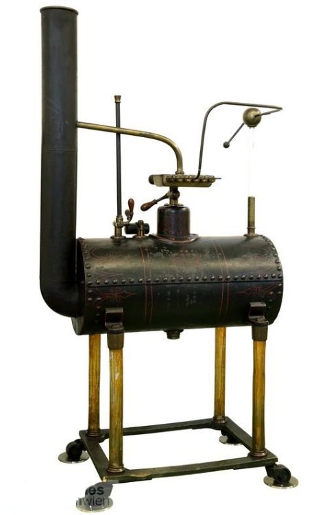 |
| Left: Armstrong Electrostatic Boiler: built 1847
This Armstrong boiler is among the holdings of the Technical Museum in Vienna, Austria. It looks rather like the version in the Discovery Museum at Newcastle-upon-Tyne. (see above) It appears it was made by Watkins and Hill of London in 1847. Watkins and Hill were active from 1818 to 1856; you can find more info on them in Graces Guide, but electrostatic boilers are not mentioned.
London 1847, London
According to the museum website, the boiler is not currently on display.
There seem to be some parts missing, such as the safety-valve. The function of the vertical tube on top of the boiler is unknown.
Note the curved brass tube running from the top of the nozzzle-box to the chimney. This was to create a draught for the fire. Similiar pipes can be seen on some of the boilers at the top of this page.
|
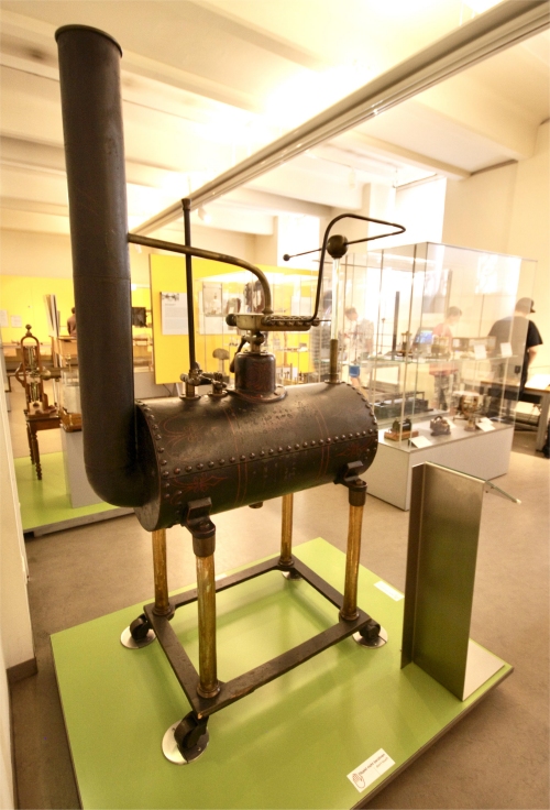 |
| Left: Armstrong Electrostatic Boiler: built 1847
This picture was taken when the boiler was on display in the Technical Museum in Vienna.
|


