
THE MODEL ENGINEER ROTARY ENGINE: 1904
I present here something I think is quite unique- detailed dimensioned drawings for the construction of a rotary steam engine. This appeared in Model Engineer and Electrician for 24th March 1904, in an article written by a Mr N Fearnley, about whom I have so far discovered nothing. The article does not give a clear statement of whether a prototype had been built. The author's assertion that losses are less with a smaller engine is true in an absolute sense, but given fixed clearances, they are relatively larger with respect to the power output.
I hope it is understood that I am not actually recommending this as a practical construction project. Read on, and you will see that I have several reservations about the design.
|
| Left: The Model Engineer Rotary Engine: 1904
Side view of the engine on its bedplate, coupled to a substantial flywheel.
The rotating valve plate can be seen to the left of the rotor. How it gets lubricated is enigmatic.
In fact, there seem to be no arrangements for lubricating the engine at all.
From Model Engineer and Electrician for 24th March 1904
|

|
| Left: The Model Engineer Rotary Engine: 1904
Cross-section of the engine, showing that it is of the revolving-door type, a lineal descendent of the Flint engine and the Eve engine. As is usual with this form of engine, there is a large amount of space in the centre of the engine which does nothing at all.
There is a line contact where the two rotors touch, and with no provision to alter the spacing of the two shafts, there is no prospect of getting a good seal here.
There appears to be no provision for end sealing beyond hoping for a good fit between rotor and casing.
From Model Engineer and Electrician for 24th March 1904
|
|
| Left: The Model Engineer Rotary Engine animated: 1904
The rotary valve cuts off the steam quite late in the cycle of rotation. Note the partial closure of the admission valve halfway through its period of opening, caused by the support rib running across the valve opening. Whether this might have caused problems I do not know.
The exhaust port is not shown.
This animation is kindly provided by Bill Todd
|
|
| Left: The Model Engineer Rotary Engine: 1904
Plan view of the engine, showing the 1:1 gearing that couples the main rotor with the revolving-door.
From Model Engineer and Electrician for 24th March 1904
|
| 
|
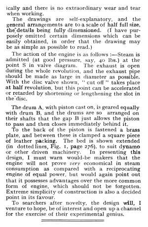
| Left: The text of the Model Engineer article
The author claims that the drawings are self-explanatory; even given sturdy Edwardian self-reliance, this seems a bit optimistic. In particular, there is no indication of the orientation of the valve plate with respect to the rotor. The major parts appear to be castings; presumably the constructor had to get these made himself.
Note that there is no possibility of changing the steam admission cutoff without dismantling the engine and replacing the valve disc.
The bit at the end about leather packing is slightly obscure. It appears that the author calls the vane sticking out of the rotor "the piston", and that the brass and leather arrangement is intended to help with sealing as it passes through the revolving door.
From Model Engineer and Electrician for 24th March 1904
|
|
| Left: The steam valve.
The strengthening rib is not a part of the intended valve operation; it simply gets in the way of admission halfway through the open period.
From Model Engineer and Electrician for 24th March 1904
|
| 
|
| Left: The Model Engineer Rotary Engine: 1904
Drawings for the two types of support bracket.
From Model Engineer and Electrician for 24th March 1904
|
|
| Left: The Model Engineer Rotary Engine: 1904
Drawing for making the flywheel. This is a pretty hefty bit of metal, and makes me suspect that the torque from the engine may have been very uneven.
From Model Engineer and Electrician for 24th March 1904
|
|
| Left: The Model Engineer Rotary Engine: 1904
Drawing for the two shafts.
From Model Engineer and Electrician for 24th March 1904
|
The author ends by expressing the hope that the combined talents of the Model Engineer readership would be able to advance the development of the rotary steam engine. This did not happen.
|
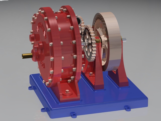
| Left: The Model Engineer Rotary Engine: 1904
A rotating view of a rotary engine. The lettering on the end of the casing is conjectural, but it looks very convincing.
This animation is kindly provided by Bill Todd
|
|
| Left: The Model Engineer Rotary Engine: 1904
The steam inlet is the brass pipe at the extreme left. Part of the grey exhaust pipe can be seen at centre top.
This very classy rendering is kindly provided by Bill Todd
|


