Helium engines

Gallery opened: 29 April 2015

Updated: 12 July 2024

Helium purification info added here.
Back to Home PageBack to The Museum

CONTENTS OF THIS PAGE

Making an engine that uses helium as its working fluid is going to require some strong justification. Helium is expensive, and it is effectively the ultimate non-renewable substance. You can always make oil out of coal if you feel the need; the technology existed in 1932. However, helium is an element, and the only way to 'make' it is to sit around and wait for a radioactive substance to emit alpha particles, which are helium nucleii.

The main reason to make a helium engine is to liquefy helium efficently, though there is some interest in helium-cooled nuclear reactors. As for liquid air, using an expansion engine rather than a Joule-Thomson throttle valve to drop the gas pressure, as in the Linde cycle, gives more efficient cooling because work is being taken out of the system. A further complication fully explained in the link is that a gas must be below its inversion temperature to be liquefied in this way, and so simple Linde cycle liquefiers cannot normally be used to liquefy neon, (BP -246.1 degC) hydrogen, (BP -252.9 degC) or helium (BP -269 degC) and the use of an expansion engine is then essential for reasonable efficiency.

HELIUM PISTON ENGINES

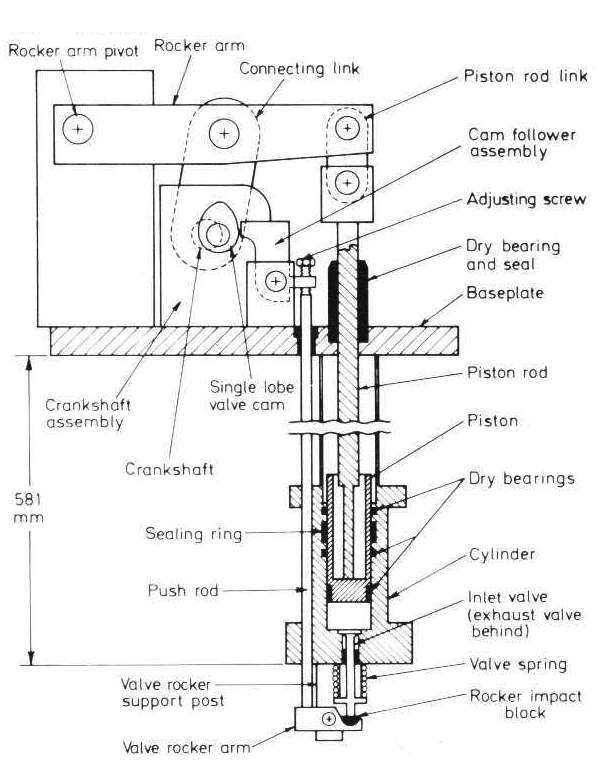
Left: Helium piston engine for wet expansion

Perhaps the most remarkable thing about this engine is how conventional it looks. It is designed to work as a wet expander- in other words liquid helium forms actually inside the engine. Claude had dreadful troubles with lubrication when was liquefying air inside an engine; the fact that it can be done routinely with helium presumably demonstrates what progress has been made in dry lubrication since 1900.

Its operation is pretty much self-explanatory, but note that the valves are at the bottom, presumably so the liquefied helium is easily cleared through the exhaust valve.

Piston expanders like this one are commonly used in the temperature range 20 - 40 K. (Kelvin or degrees Absolute) Wet expanders are preferred as they are more efficient than dry expanders, in which the gas cools but does not liquefy. Typically wet piston expanders are 80% efficient compared with dry piston expanders at 70 - 75%.

The power output is tiny compared with that required to compress the helium in the first place, and is usually not worth trying to exploit it. It is usually dissipated in a small fan.

From Cryogenic Engineering Ed B A Hands. Academic Press 1986

HELIUM TURBINES

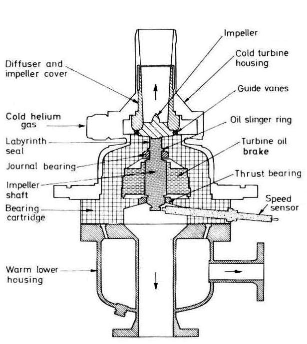
Left: Section through a helium turbine

It is well known that in steam power generation turbines are more efficient and more reliable than reciprocating engines. In the helium business things do not work the same way. Turbines can be and are used as expanders to remove work from the helium, but in some cases piston expanders are more efficient, and maintain their efficiency over a wide range of flow rates, making plant operation easier.

This is a turbine expander for a large helium refrigerator. The helium leaves the turbine and exhausts upwards.

Note that no details are given of the bearing, except to say it is a 'journal bearing' which suggest a simple sleeve bearing. How and if it is lubricated are not stated, but the presence of an 'oil slinger ring', which would throw oil off the shsft by centrifugal force, suggests- well, oil. The power output of the turbine appears to be absorbed in an 'oil brake' which seems to be a simple cylinder immersed in oli, to absorb the power output in viscosity losses.

From Cryogenic Engineering Ed B A Hands Academic Press 1986. Image originally from Sulzer Bros.

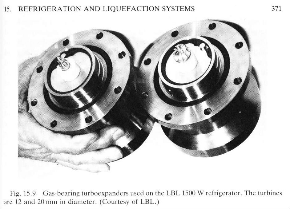
Left: Two helium turbines of different size

Note the very small impellers compared with the size of the man's hand.

LBL is the Lawrence Berkeley Laboratory in California, which lives at 1 Cyclotron Rd, Berkeley, CA. (A well cool address) The elements Lawrencium, Seaborgium, and Dubnium were discovered there.

From Cryogenic Engineering Ed B A Hands Academic Press 1986

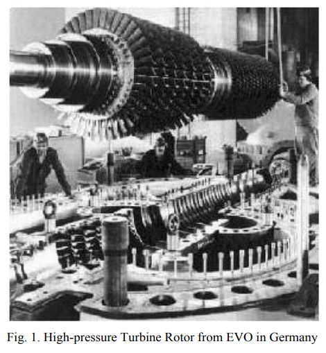
Left: The helium HP turbine of the HHT test system: Germany

There is currently interest in nuclear reactors cooled by helium, which is then expanded in a helium turbine. Coupling a high temperature gas-cooled nuclear reactor with a closed-cycle gas turbine using helium was first suggested by Professor Curt Keller (co-founder of the closed Brayton cycle gas turbine with Professor Ackeret) in 1945. Helium was chosen because of its radioactive stability and high thermal capacity. Helium offers other important advantages, including a lower Mach numbers and a higher Reynolds numbers than with the use of air in turbines.

The first and largest helium turbine to date (the HHT project) was constructed in Germany in 1968. It was rated at 50 MW at 750 degC. The helium was heated by a fossil-fired furnace giving 53.5 MW The operating helium pressure for tests was up to 1 MPa, equal to 145 psi.

A later project was the HHT, consisting of the Oberhausen II helium turbine cogeneration plant operated from 1974 to 1988 by the German utility EVO (Energie Versorgung Oberhausen AG), and a second facility for high-temperature testing (HHV) built in 1981.

The HHT turbomachinery was a two-shaft arrangement. The high-pressure (HP) turbine, which has a rotational speed of 5,500 rpm, drove the low-pressure (LP) compressor and high-pressure (HP) compressor on the first shaft. The low-pressure (LP) turbine on the secons shaft was directly connected to the generator with a synchronous rotational speed of 3,000 rpm. The mass flow rate of helium was 84.8 kg/second.

Source: A Review Of Helium Gas Turbine Technology For High-Temperature Gas-Cooled Reactors by Hee Cheon No et al, 2007

Helium-cooled reactors have a Wikipedia page.

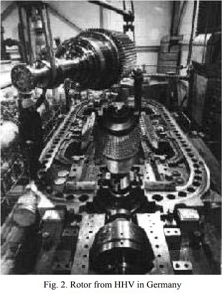
Left: The turbine rotor of the HHV test system: Germany

Source: A Review Of Helium Gas Turbine Technology For High-Temperature Gas-Cooled Reactors by Hee Cheon No et al, 2007

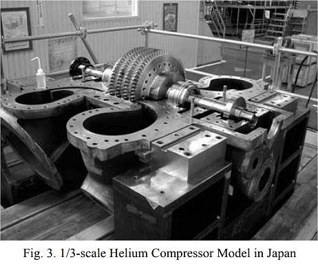
Left: One-third scale helium compressor: Japan

Source: A Review Of Helium Gas Turbine Technology For High-Temperature Gas-Cooled Reactors by Hee Cheon No et al, 2007

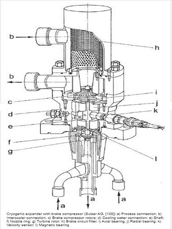
Left: Sulzer helium turbiner

This helium turbine for refrigeration was manufactured by Sulzer. The turbine in the lower half of the unit is braked by a compressor in the upper half. The turbine is supplied with helium through the central tube via the pipes a and the helium exhaust is led away through the central pipe. (also unhelpfully labelled a)

Note that the compressor is water-cooled via pipe d, which is rather surprising considering that there is (presumably very cold) helium apparently only a few inches away. Note also the magnetic bearing; since no coils are shown this appears to use a permanent magnet.

The turbine actually generates little mechanical power and it is not worth recovering, so the brake compressor discharge is returned right back to the brake compressor intake via a throttling control valve and a water cooled heat exchanger that removes the heat of compression. The control valve regulates the speed of the turbine by controlling the resistance offere to to the compressor discharge.

Many thanks to by Kerry Stiff for providing this diagram and accompanying information.

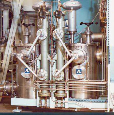
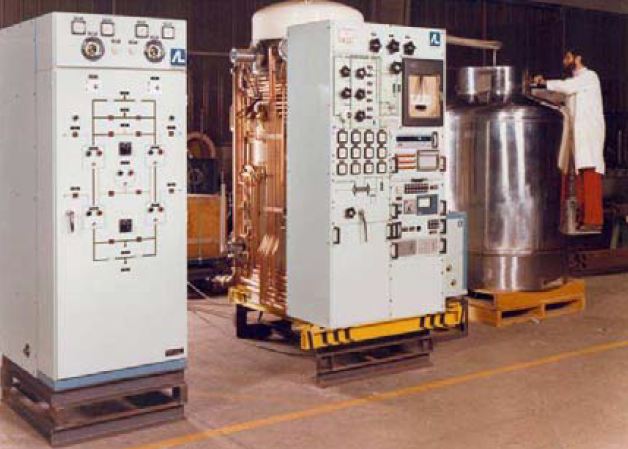
Left: Helium Liquefaction Plant: France

In 1964, Air Liquide began to develop helium liquifiers using cryogenic expansion turbines running on static gas bearings. The first turbine helium liquefier was sold in 1968. It produced 35 Litre/hour of liquid helium and had a liquid nitrogen pre-cooled one-turbine Claude cycle and an external liquid nitrogen cooled purifier. This picture is from 1968 or later, and shows a helium liquifier on the right and a purifier on the left. The big silver tank is a Dewar vessel for storing the liquid helium.

Helium needs to be purified because at liquid helium temperatures any other gas is a solid and will freeze on heat exchanger surfaces, rendering them inoperative. Contamination of the helium typically occurs when some of it boils off; helium is expensive so this caught in a gas bag for later liquefication and re-use.

In the smaller systems the purifier consists simply of two heat exchangers. The flow in one eventually ceases as the heat exchange surfaces become covered with frozen water, CO2, etc. The flow is then switched to a second heat exchanger while the first is defrosted with nitrogen until it is clear, and it is then evacuated and switched back into use while the second heat exchanger is cleaned in the same way; rinse and repeat. The two flow paths are represented on the front of the purifier cabinet at the left.

Source: Overview of Air Liquide Refrigeration Systems between 1.8 K and 200 K. by Gondrand et al, 2014

Furthe information on purification courtesy of Kerry Stiff, to whom much thanks.

Left: Twin Helium Turbines in Grenoble, France

In 1972, France and Germany collaborated to build a High Flux nuclear reactor, a form of reactor generating intense beams of neutrons for the generation of isotopes and various fields of research. Itis at the Institute von Laue Langevin (ILL) in Grenoble, France.

This project required a very powerful (for 1972) refrigerator, capable of removing 10 kW of thermal energy at 25 Kelvin, to re-condense the deuterium vaporised by the neutron beam power. To achieve this a mass flow rate of 320 gm/sec was required; the helum turbines available in 1972 were only handling 15 gm/sec. A serious design upgrade was required.

Air Liquide wisely decide to split the 320 gm/sec between two turbines handling 160 gm/sec, but even this required the turbines to handle more than ten times as much mass flow as ever before. The technique was a great success, and in 2013 the refrigerator had accumulated around 200,000 hours of operation. The Museum Staff are unable to say exactly what is what in the picture at present, but it seems likely the turbines are in the two large vertical cylinders with 'AL' on the side.

According to Air Liquide, in 2013 the last turbine 'incident' had happened in 1991. They are coy about it, saying no more, but presumably a bearing seized and there was a 'Rapid Unscheduled Disassembly'. So far the rotational speed at which these helium turbines operate is unknown, but some Korean versions run at 230,000 rpm. If a turbine seizes at that speed the results are probably dramatic.

Source: Overview of Air Liquide Refrigeration Systems between 1.8 K and 200 K. by Gondrand et al, 2014

Back to Home PageBack to The Museum EntranceTop of this page