 |
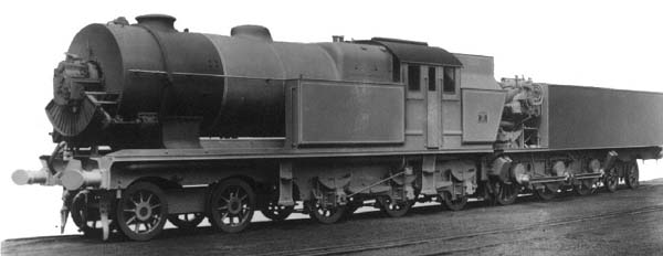
| Left: The Beyer-Ljungstrom Turbine Locomotive.
The smokebox contained, ahead of the funnel, a rotating-media air preheater warmed by the flue gases, turned by a drive taken from the draught fan turbine. The sector-shaped thing on the front of the smokebox is the drive to the friction rollers that rotated the preheater.
The draught fan turbine can be seen on the centre front of the smokebox door.
|
The Beyer-Ljungstrom locomotive looks conventional at first sight, but a second look shows six coupled driving wheels under the tender, which in fact carries a turbine power plant. The tender also carries the condenser, which permits direct coupling to the turbine exhaust through a large area. duct This is essential to get the best efficiency from a condensing turbine because of the large amount of expansion and therefore the big volume of exhaust steam.
The loco was built by Beyer-Peacock of Manchester, UK, the turbine technology being provided by Ljungstrom Anturbin of Sweden.
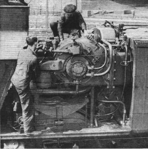 |
| Left: A very rare photograph of the turbine unit.
The turbine had a single impulse stage followed by 18 rows of reaction blades. Its design power was 2000hp at 10,500rpm, corresponding to a speed on the rails of 78mph. Design steam conditions were 300 lb/sqin at 200 degC superheat.
The large rectangular cross-section exhaust duct can be seen leaving the turbine assembly at the right.
|
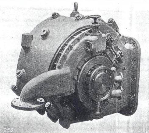 |
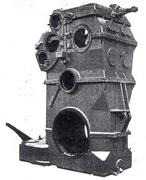
| Left: The main turbine unit before assembly.
The turbine was designed for an output of 2000 HP at 10,500 rpm, which corresponded to a locomotive speed of 78 mph. The turbine drove the leading driving axle via three stages of reduction gearing having a total ratio of 25.2 to 1.
The steam inlet pipe is at the left. The large rectangular cross-section exhaust duct is at the right. Note the lifting eye on top of the casing.
From Engineering
|
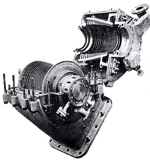 |
| Left: The main turbine opened up.
The single-row impulse wheel can be see, followed by 18 rows of reaction blading.
The steam inlet pipe is at top right; the large exhaust duct is at the bottom.
From Engineering
|
 |
| Left: The gear casing ready to receive the gear wheels.
The size of this assembly gives some idea of why the adhesion weight on the tender was as high as it was.
From Engineering
|
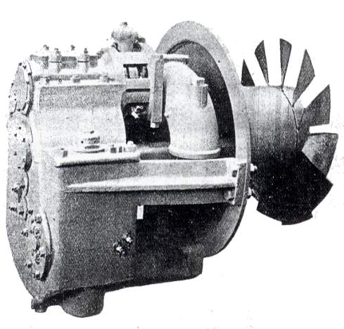 |
| Left: The draught fan and its turbine.
One of the drawbacks of making a condensing locomotive is the absence of any exhaust steam blast up the chimney to induce a draught through the boiler tubes and furnace. This process is vital for achieving the high steaming rates required from a locomotive boiler. Without it, recourse to a power-driven draught fan was needed; in this case a small steam turbine was used to drive what looks like a rather crude fan. The draught turbine also rotated the air preheater.
The curved item at top centre is the draught turbine exhaust pipe. The exhaust was passed to the condenser unit by a pipe on the left side of the locomotive. This can be seen in the plan of the boiler unit below.
Note: the auxiliary turbines are not shown at the same scale as the main turbine components above. They were naturally much smaller.
From Engineering
|
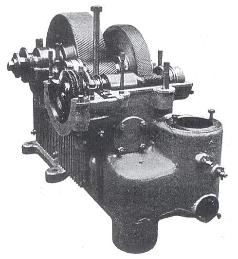 |
| Left: The condenser turbine and gearbox.
The condenser turbine was a small auxiliary turbine mounted behind the main propulsion turbine. It powered the condenser fans by shaft drive.
The turbine wheels can be seen just above the semi-circular flange to the left. There are two stages of helical reduction gearing.
From Engineering
|
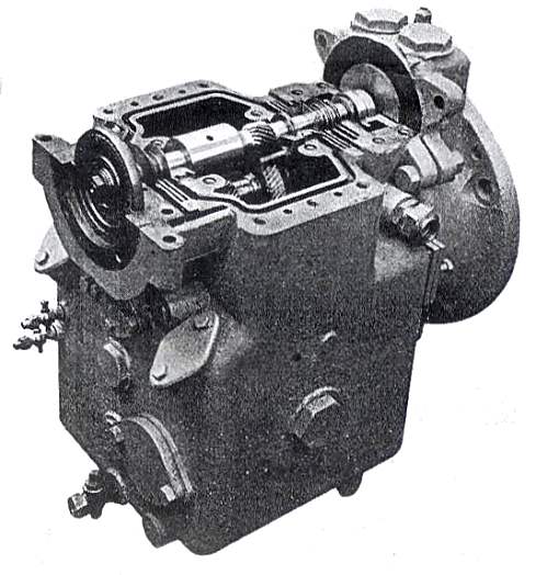 |
| Left: The feed pump turbine and gearbox.
From Engineering
|
The locomotive ran on the LMS during 1926-28, but was then withdrawn and eventually dismantled. Great things had been expected of this courageous design, but results were not good, partly due to leaks of air into the condenser, spoiling the vacuum, but mostly down to poor combustion. The air preheater is believed to have contributed to this. The greatest turbine output obtained was 1650 HP. The locomotive was finally dismantled in 1928.
The design raises an obvious question; surely it is inefficient to have none of the weight of the boiler section (all 54 tons of it) available for adhesion? The three driving axles on the rear section only have 54 tons between them for adhesion, with the rear bogie carrying another 19 tons.
|
Above: Drawing of the boiler part. From Engineering. This drawing is 1200 pixels wide.
I'm afraid some sideways scrolling may be needed here.
Reproducing it at any smaller scale would make the text unreadable.
|
|
Above: Drawing of the tender carrying the turbine and condenser. From Engineering This drawing is 1098 pixels wide.
The condenser was fitted with four large fans to draw air through the condenser. These were driven by another auxiliary turbine.
|


