The Holcroft-Anderson Recompression Locomotive had a long and complicated history.
In brief, engineers Harry Anderson & John McCallum had invented a process for the recompression of exhaust steam to improve efficiency; this was proven to work in a static installation at Surbiton Power Station in 1927-29.
Harry Holcroft, Technical Assistant to Richard Maunsell, the Chief Mechanical Engineer of the of the Southern Railway, recalled it thus:
"It was on November 24th, 1927, that Maunsell called me into his office to say that a company styling itself 'The Steam Heat Conservation Co.' was claiming that they had developed a new departure in the use of steam by way of recovering much of the heat loss normally sustained; would I go to their office in the City to investigate and report back to him?"
"On calling at the office I was received by R J Petersen, a stockbroker, who was the Chairman, and H P H Anderson, the inventor of the system. The former explained that the invention, which was a new means of condensing exhaust steam, had been originated in marine engineering circles in Glasgow and developed to the point at which it was a practical proposition. It would, however, be more advantageously employed in the case of engines exhausting to atmosphere than in those fitted with the usual form of condensing, like marine engines. For this reason the exploitation of the invention had been taken up in London, and a number of business men in the city had subscribed capital towards the formation of a company to this end."
(From Holcroft's book Locomotive Adventure: 50 Years with Steam, Vol 1, publ London, Ian Allan, 1962)
Holcroft visited the privately-owned Surbiton Power Station installation the next day and was impressed with the concept. A controlled test at Surbiton with Holcroft present showed a 29% fuel saving compared with atmospheric working.
Figure 2: The layout on each side of the Holcroft-Anderson Recompression Locomotive
It should be said that Mechanical Vapour Recompression, as it is called today, is a perfectly sound thermodynamic process. If you need some steam at modest pressure, it is often more economic to compress the exhaust vapour and re-use it rather than generate more steam at high pressure in the boiler. Today this recompression is done either by steam-powered ejectors or electrically driven centrifugal compressors, usually to provide process steam.
A locomotive converted to use the process was delivered to the Southern Railway (UK) in 1930. Steam was raised in the boiler, passed through the cylinders and then, via grease-separators, to evaporative coolers either side of the engine, part-filled with water from the tender; the steam arising from this was piped to the chimney. The steam in the cooler pipes was only partly condensed, but greatly increased in density, it was recompressed by compressors driven by vertical steam engines each side of the firebox, and re-entered the boiler via clack boxes either side of the steam dome. These engines also drove gear-type pumps that brought water from the tender for the coolers and boiler make-up. A valve allowed conventional working with the cylinder exhaust going through a blast-pipe; this was used for starting.
A steam-driven fan attached to the inside of the smokebox door provided the draught; the engine driving it was an unusual design patented by Anderson, having four cylinders and normally working at 1000 rpm with a 25%cut-off; while it is often described as a 'rotary engine' it appears to have been a radial design. (Unless it was a rotary engine in the sense that the crankshaft was stationary and the cylinders went round with the fan. As originally manufactured the fan worked backwards, blowing dust and smoke out of the firebox door. A quick redesign of this feature was called for, but the fan draught system still seems to have given a quite excessive amount of trouble, considering the simplicity of its task. A very clear example of the risks involved in trying to do too much innovation all at once.
 |
|  |
| Left: The Holcroft draught fan and engine
The fan sucked in air around its periphery, and blew it into the central circular structure, which communicated with the chimney.
From Part 2 of Holcroft's article: 13th Sept 1946 issue of Engineering, p227-9
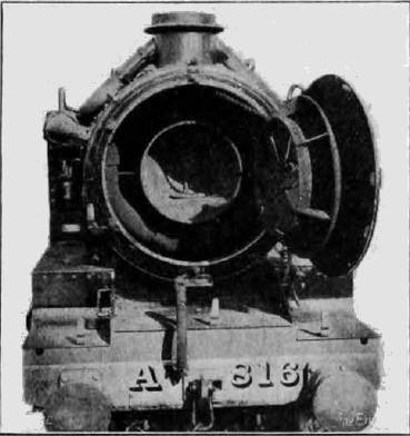
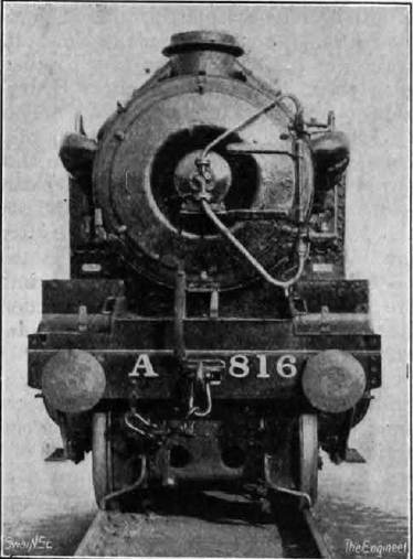
|
Above are the only known photgraphs of the fan system. The fan engine (right) only appears as a round casing which could well have been a true rotary engine. Steam was supplied through the upper rotating joint of the smoke-box door. The exhaust steam was taken out through the lower and larger diameter pipe and bottom rotating joint, and then passed to the smoke-box, probably fulfilling some sort of small-scale blast function.

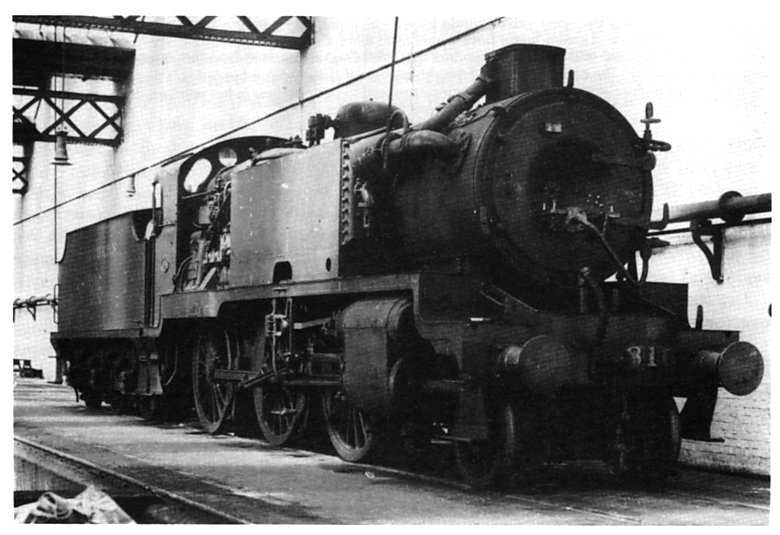
Figure 3: The Holcroft-Anderson Recompression Locomotive as illustrated in Railway Magazine in 1949
Several interesting features not visible in Figure 1 are shown in Figure 3 above. There is a pipe leading from the front of the cooler to the side of the chimney, which is the steam exit route shown in Figure 2. The fan engine is barely visible, being apparently recessed into the smoke-box door. The supply and exhaust pipes for this engine can however be clearly seen; they appear to have rotating joints so the smoke-box door can be opened on its hinges. The strange camouflage pattern on the side of the cooler is probably just overheated paint. The chimney here is different from the very ugly square item in Figure 1.
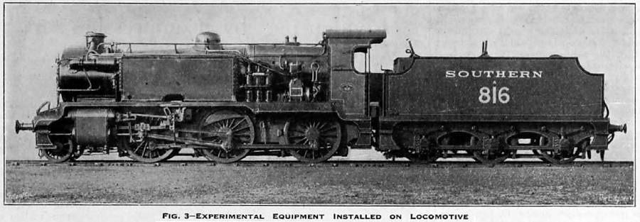
Figure 4: The Holcroft-Anderson Recompression Locomotive as illustrated in Engineering for 13th Sept 1946
The loco was put through trials until 1934, suffering various problems, especially with the draught fan, until those concerned appear to have lost interest. The engine was reconverted to standard form in 1935.
Here are some nuggets of hard fact:
Steam conditions200 psi
Wheel layout2-6-0
Weight66tons 4cwt
| | | | | |
Details of the design were published in the journal Engineer:
Holcroft published a three-part account of the work entitled "Condensing by compression: a locomotive experiment", in Engineer.
Part 1 6th Sept 1946 issue, p202-3
Part 2 13th Sept 1946 issue, p227-9
Part 3 20th Sept 1946 issue, p248-9
There followed a letter from E B Parker in the 4th October 1946 issue; see p304. Amongst other points about draught and snifting valves, he said:
" It is hardly an exaggeration to say that every unsuccessful attempt to produce a condensing locomotive has failed to a large extent through the unsatisfactory performance of the induced draught fan."
There was further discussion on this topic by H.H. Carr and Oliver Lyle in Engineer, 1946, p327; p350; p446: 183, 89-91. (See Duffy)
For more information on Harry Holcroft see Wikipedia, and steamindex.com.
Here is an account of the trials:
"The Anderson condensing system uses a process known as mechanical vapor recompression. It was devised by a Glasgow marine engineer, Harry Percival Harvey Anderson. The theory was that, by removing around 600 of the 970 British thermal units present in each pound of steam (1400 of the 2260 kilojoules in each kilogram), it would be possible to return the exhaust steam to the boiler by a pump which would consume only 1-2% of the engine's power output. Between 1925 and 1927 Anderson, and another Glasgow engineer John McCullum (some sources give McCallum), conducted experiments on a stationary steam plant with encouraging results. A company, Steam Heat Conservation (SHC), was formed and a demonstration of Anderson's system was arranged at Surbiton Electricity Generating Station.
SHC was interested in applying the system to a railway locomotive and contacted Richard Maunsell of the Southern Railway. Maunsell requested that a controlled test be carried out at Surbiton and this was done about 1929. Maunsell's technical assistant, Harold Holcroft, was present and a fuel saving of 29% was recorded, compared to conventional atmospheric working. The Southern Railway converted SECR N class locomotive number A816 (later 1816 and 31816) to the Anderson system in 1930. The locomotive underwent trials and initial results were encouraging. After an uphill trial from Eastleigh to Litchfield Summit, Holcroft is reported as saying:
"In the ordinary way this would have created much noise and clouds of steam, but with the condensing set in action it was all absorbed with the ease with which snow would melt in a furnace! The engine was as silent as an electric locomotive and the only faint noises were due to slight pounding of the rods and a small blow at a piston gland. This had to be experienced to be believed; but for the regulator being wide open and the reverser well over, one would have imagined that the second engine (an LSWR T14 class that had been provided as a back-up) was propelling the first".