Separate pages for Heilmann locos: 12 Mar 2015
Updated


Separate pages for Heilmann locos: 12 Mar 2015 |
The Heilman locomotives were the first steam-electric designs, using a reciprocating steam engines to drive DC generators, which in turn powered electric motors mounted directly on the axles.
![]()
THE FIRST HEILMANN LOCOMOTIVE:
THe locomotive was named Le Fusée Electrique. (The Electric Rocket) a reference to Stephenson's Rocket.
Jean-Jacques Heilmann, proprietor of the Société Industrielle de Moteurs Électriques et ŕ Vapeur in Le Havre, took out his patent for a steam-electric locomotive on July 18, 1890, and the first prototype was built in 1892-93. Heilmann and his coworker Drouin began with static tests to determine whether DC or the recently introduced 3-phase AC would be most suitable for their purposes. It was quickly found that DC would be best, as it allowed the steam-engine and generator to work at a constant efficient speed, while the traction motor speed could be quite different.
Heilmann was from Alsace, which no doubt accounts for his rather Germanic-sounding name. A Joshua Heilmann was a noted textile engineer in Mulhouse (often regarded as the industrial capital of Alsace) working on woolcombing machines and mechanical embroidery equipment, around 1845. Very possibly he was the father of J J Heilmann.
The chassis of Le Fusee was 16.3 m long overall, mounted on two 4-axle bogies. Each axle was driven by a 60 hp electric motor. The total weight (and I haven't yet worked out if this was wet or dry) was 110 tons. Electricity was generated by a 400 kW generator, driven by a horizontally-opposed two-cylinder steam engine. The field current for the generator was supplied by a small vertical steam engine driving a dynamo.
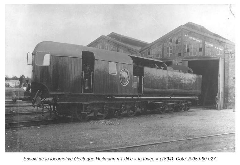 | The Fusée, the first Heilmann locomotive, on trials in 1894
|
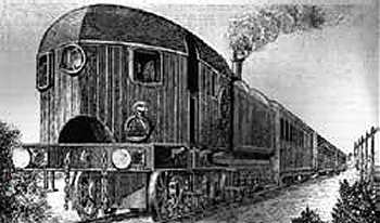 | The Fusée, the first Heilmann locomotive, fitted with a rather unattractive wooden body
|
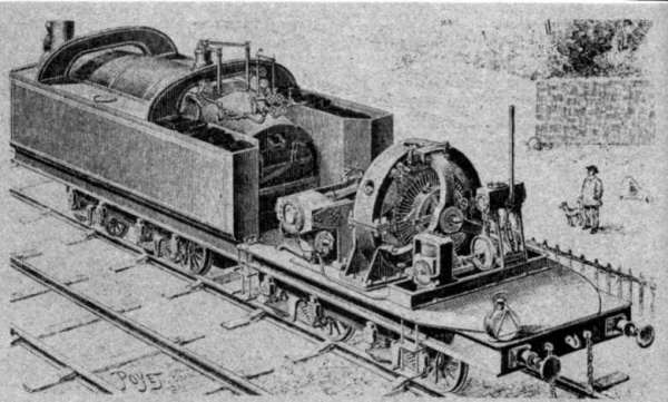 | The first Heilmann, with the wooden body removed.
|
 | The first Heilmann
|
 | Another picture of the first Heilmann with the body removed
|
 | Some details of the first Heilmann.
|
After completion the locomotive Fusée, in Autumn 1893, made a test run on the Le Havre- Beuzville line. The locomotive gave good results, especially as regards its high starting tractive effort. On 9 May 1894 it set off on the Compagnie des Chemins de Fer de l'Ouest (West) network from Paris St-Lazare station and hauled to Nantes and back a special train carrying 250 guests. This excursion went smoothly with an average speed of 75 km/hr, while for a short time a maximum speed of 107 km/hr was achieved. The machine could haul a passenger train of 80 tons at 100 km/hr.
One problem that appeared was difficulty of communication between the driver and the fireman, who were separated by the engine and generator. Testing continued, about 2000 km in total being covered, and this gave the Ouest railway confidence to order two more Heilmann locomotives of greater power: see below.
 | The engine of the first Heilmann: sectional endview
|
 | The engine of the first Heilmann: exterior endview.
|
 | The engine of the first Heilmann: plan view.
|
 | The Lentz boiler of the first Heilmann
|
There is a combustion chamber between the grate and the boiler tubes. No superheater tubes are visible.
 | Another Lentz boiler
|
This boiler type was originated by Hugo Lentz (1859–1944) an Austrian mechanical engineer. He is better known for the Lentz oscillating-cam poppet valves fitted to a good many locomotives. A similiar type of boiler was used on the Lancashire & Yorkshire Railway but does not appear to have been a great success.
![]()
A MODEL OF THE FIRST HEILMANN
So far I have found no photographs of the first Heilmann, though some must surely exist somewhere. What I did find, quite unexpectedly, was a fifth-scale model in CNAM, the Conservatoire National des Arts et Metiers in Paris. (This is a wonderful museum, full of all sorts of gems such as Cugnot's steam carriage- the original, not a replica. You can also get a lunch that fully upholds the reputation of French cuisine)
This model was built by Jean Jacques Heilmann himself, in 1903. This is after the trials of the second version, and apparently by this time it was clear that the Heilmann concept was not going to be adopted. This eems a little strange; you would have thought the model would have been built before the first full-size locomotive was constructed. But, that's what it says on the label in the CNAM, so there it is.
These photographs were taken in available light, with a handheld camera and through the glass case, so I'm afraid the image quality is not stunning.
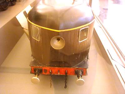 | Model of the first Heilmann: the front.
|
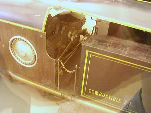 | Model of the first Heilmann: the engine.
|
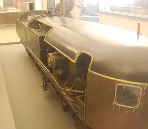 | Model of the first Heilmann: the side.
|


