Gallery opened: Jan 2004
Updated: 4 July 2016
Engine pic added


The Egyptian Steam-Motor Locomotive of 1938 |
Gallery opened: Jan 2004
|
|
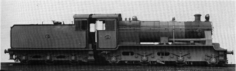 | Left: The Egyptian Steam-Motor Locomotive. This looks like a works photograph
|
Four of these steam-motor locomotives were built by the North British Locomotive Company of Glasgow in 1937, in association with Sentinel, for passenger haulage. The works numbers were 24413 - 24416; they were supplied to the Egyptian State Railway at the beginning of of 1938. They were propelled by two Sentinel steam-motors, independently powering the two driving axles. These motors were already proven to give low maintenance costs and favorable consumption rates for steam and lubricating oil, as well as even torque. The boiler was a conventional loco-type, unlike other Sentinel designs, and was built by the North British Locomotive Company, who also provided the frames and tenders.
It is believed that these locomotives, with their fully enclosed machinery, were ordered because conventional exposed coupling rods and valvegear suffered severe wear from the sand of the Egyptian environment.
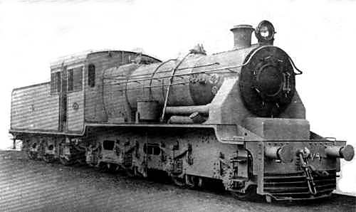 | Left: Another works photo of the Egyptian Sentinel locomotive motor
|
Sentinel had considerable experience in making steam-motor locomotives, though most of them were small 0-4-0 shunting engines, with vertical boilers and chain drive. They have their own page here. A large number of Sentinels were supplied to the British LNER. See also here: Sentinels on the LNER.
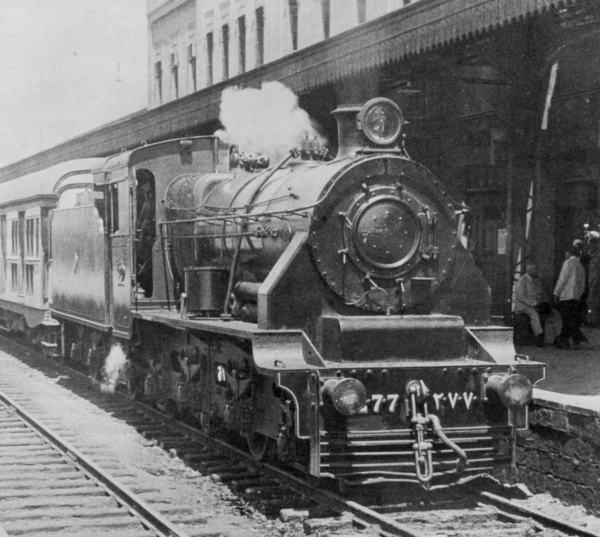 | Left: One of the Egyptian Steam-Motor Locomotives (No 277) at Cairo Main station
|
They have been described as "not very successful" but in what way they were inadequate is not very clear; according to one source their machinery proved no more resistant to sand than conventional designs, and once the sand had got in, it was harder to get it out again. They were soon taken out of service but wartime motive-power shortages saw them in use again in 1943. They were presumably scrapped after the war but no details of this are currently known.
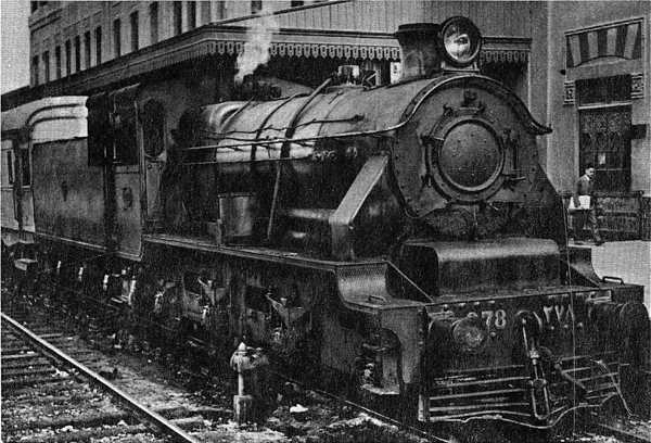 |
| Left: Another of the Egyptian Steam-Motor Locomotives (No 278) at Cairo Main station |
 |
| Left: The Egyptian Steam-Motor Locomotive: elevation |
 |
| Left: The Egyptian Steam-Motor Locomotive: plan |
 |
| Left: Side section of one of the Steam-Motors |
Steam-motor details.
Each steam motor was a fully enclosed two-cylinder double-acting single-expansion design; working pressure was 200 psi. The two cranks were set at 90 degrees as usual to avoid dead-centre problems. The motor housing was supported at the front on the locomotive framework, by a beam with rubber shick absorbers, and at the rear by the driving axle. Power transmission from the roller-bearing crankshaft to the driving axle was by gears inside the steam-motor housing. Each motor (or engine, if you prefer) produced 200 hp, the twin cylinders having an 11in bore by 12in stroke. The valvegear was a modified Hackworth design, having piston valves of 5.5in bore. Roller bearings were fitted on the crankshaft, but all other bearings had plain bushes with forced oil lubrication.
The starting tractive effort was 7860 kg. Steam consumption at full load, within the range 300 - 500 rpm crankshaft speed was from 9.1 to 9.8 kg/kWhr. Maximum speed was 51.5 mph, corresponding to a motor speed of 600 rpm.
 | Left: Plan of one of the Steam-Motors
|
There were two oil pumps for each motor, mounted on the rear housing wall, to provide forced lubrication. These can be seen at the extreme right of the drawing. They were driven by two eccentrics on the axle shaft.
 | Left: Longitudinal section through one of the steam motors
|
 | Left: Section through crankshaft and axle
|
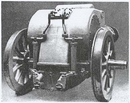 | Left: External view of a steam motor
|
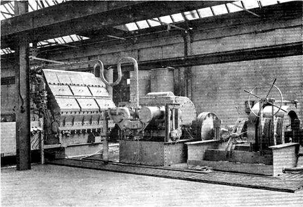 | Left: One of the 200 hp Egyptian locomotive motors on test at the Sentinel works.
|
![]()

|