Updated:
6 June 2006
The first Belluzzo locomotive was drawn to my attention by Alex Stirrat, who also provided the picture.


The first Belluzzo locomotive was drawn to my attention by Alex Stirrat, who also provided the picture.
Belluzzo & The Italian Turbine Locomotives |
Updated: |
|
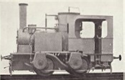 | Left: Belluzzo's quadruple turbine engine of 1907
Since the turbine casings are offset from the axles, there was clearly some sort of reduction gearing involved. This would be essential as turbines spin very much faster than locomotive wheels. There was in fact single stage reduction gearing of 8:1 ratio on the outside of the wheels. All later turbine locomotives used two or three stages of gearing. |
The locomotive was a conversion of an 0-6-0 built in 1876; one axle was removed. The 30m2 evaporation surface and boiler pressure of 140psi were retained. (It was 150psi in some accounts)
 | Left: Side elevation of Belluzzo's 1907 engine.
|
 | Left: Section through the turbine. Moving blades are shown in pink, fixed blades in blue.
|
This unique locomotive lasted for thirteen years, being dismantled in 1921. Trials would certainly have been run, but if it was put to actual work is unknown. Possibly an inadequate reduction ratio and resulting inefficiency was the downfall of the project, in that ten years elapsed before the next Italian turbine locomotive. No details are currently known of its performance.
Just the the basic facts, please, ma'm...
Wheels0-4-0
Weight26 tons
Length 23ft 4in
Heating surface 323 ft2
Boiler pressure 140/150psi
Max turbine speed2400rpm |
THE BELLUZZO-BREDA TURBINE OF 1931.
Until very recently, I thought no information about this loco could be found, and it is still in very short supply. However here it is...
In 1931, Belluzzo acted as design consultant for a 2-8-2 turbine loco built by the Ernesto Breda company. It had high and low pressure turbines. It is thought to have been tested in the Breda works at Milan, but apparently the Italian State Railway would not allow it to be run on the main line; whether this indicates it was an obvious failure that would only delay traffic when it broke down is uncertain.
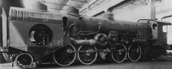 | Left: The Belluzzo-Breda Turbine Locomotive.
|
Most of the information in this paragraph is deduced from the engineering drawings below, so accuracy-wise you'd better keep your fingers crossed. The condenser was mounted under the front of the boiler, and its circulating water was cooled by the cooling unit at the very front of the locomotive. The boiler was conventional, with the usual super-heater tubes, and draught was induced by a triple blastpipe. A draught fan, as used in many other turbine locomotives, was explicitly ruled out as these always gave trouble when they were eroded by ashes and cinders in the exhaust gases. This raises the question of the purpose of the condenser, as if it was intended to conserve water, blowing steam up the chimney would not be helpful. (Probably there was a valve that shut off the chimney blast when it was not needed, but so far this is not clear from the engineering drawings below) It is therefore likely that the condenser was instead intended to provide a vacuum for the turbine exhaust, to increase efficiency.
Another design decision was to keep the condenser on the locomotive, rather than put it in the tender, as this avoided large-diameter flexible pipework for the exhaust running between locomotive and tender. The Swiss Zoelly Turbine took a similiar approach, but kept the water cooler on the tender.
One unusual feature of this machine was that it appeared to have two chimneys; one above the cooler (at the left in picture above) and one further back, above the front two axles. In fact the front "chimney" was another air outlet for the water cooler, and was fitted with a fan driven by a small auxiliary turbine. This turbine also drove the condenser circulating pump.
 | Left: Drawing #1. The front of the Belluzzo-Breda Turbine Locomotive.
G is an opening that gives access to the smokebox. |
|
Above: Drawing #2. Vertical section of boiler, smokebox and turbine gearing of the Belluzzo-Breda Turbine Locomotive.
|
|
Above: Drawing #3. Horizontal section of the Belluzzo-Breda Turbine Locomotive.
The high-pressure turbine is on the left, with eight nozzle-control valves visible on the top of its casing. |
 | Left: Drawing #4. Two vertical sections through the Belluzzo-Breda Turbine Locomotive.
|
 | Left: Drawing #5. Two more vertical sections through the Belluzzo-Breda Turbine Locomotive.
H is the auxiliary turbine, driving the transverse fan shaft through what looks like reduction gearing at G. |
 | Left: Drawing #6. Front elevation of the Belluzzo-Breda Turbine Locomotive.
|
Just the the basic facts, please, ma'm...
Length 47ft 1in |
And that's all she wrote. No other information appears to have survived, not even the boiler pressure.
THE ITALIAN STATE RAILWAYS TURBINE OF 1933: No 685.410
In 1933 the Officine Meccaniche Miani-Silvestri-Grodona-Comi (I think I've got that right) rebuilt a type 685 2-6-2 at Florence for the Italian State Railways. It was built for express service, and was a 2-6-2 with the turbine mounted at the front. No condenser was fitted. It was tested between Florence & Pistoia, (a rail journey I have made myself) but seems to have never been heard of again, which indicates that this design too was unsuccessful. The design maximum speed was 130 km/h but what it was actually capable of is unknown.
 | Left: The Italian State Railways Turbine Locomotive.
|
The turbine and jackshaft of this locomotive is at the front. Forward and reverse turbines built by Schwartzkopff were mounted on the same shaft, with nozzle control by a group of four valves. Early in testing it appears that a turbine bearing seized, causing severe damage to the blading. It was not repaired and trials were abandoned; that was the end of steam-turbine experiments in Italy.
Just the the basic facts please, ma'm...
Wheels2-6-2
Weight72 tons
Length ???
Heating surface 2056 ft2
Boiler pressure 175psi
Max turbine speed7000rpm |
POTTED BIOGRAPHY OF GUISEPPE BELLUZZO.
Giuseppe Belluzzo was born in Verona in 1876. He taught in Milan and then Rome, and was the author of more than fifty technical books. He was involved in installing turbines in Italian cruisers and battleships.
Regrettably Belluzzo went on to a career in fascist politics; He was elected to Parliament and was Minister of National Economy from 1925 to 1928. No doubt he claimed he had made the trains run on time...
He also, heaven help us, got involved in promoting mythical Nazi flying saucers: see Giuseppe Belluzzo. (external link) You will find that Googling on "Giuseppe Belluzzo" will get you a lot more misinformation on flying saucers than it will information on turbine locomotives; of such is life. I am not responsible for the content of external sites.
Belluzzo died in Rome on May 21st, 1952.
![]()

|