Gallery opened Jan 2004
Updated: 12 May 2008
Reduction gear pics added


The Argentine Turbine Locomotive: 1923 |
Gallery opened Jan 2004 |
|
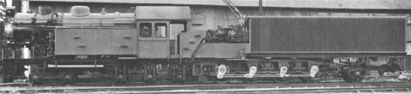 | Left: The Argentine Turbine Locomotive.
|
This turbine locomotive was built by the Swedish firm NOHAB, under licence of the Ljungstr—m patents, for passenger and goods haulage on the metre-gauge Tucuman-SantaFe route in Argentina. This was an important sugar-cane route. The 797 km stretch had no suitable feed water (and no water at all for 400 km of its length) so a condensing locomotive that did not require replenishing over this distance was needed.
The design derived from the first Ljungstr—m turbine locomotive. The nominal power output was 1800 hp, and the design speed was 65 km/hr.
 | Left: Side view of The Argentine Turbine Locomotive internals
|
The boiler was oil-fired and conventional in construction except for the rotary air heater in front of the smokebox, which raised air to 300 degC. Unlike the first Ljungstr—m locomotive, the four condenser cooling fans blew downwards. This was intended to give a more even distribution of cooling air in the condenser, which had to operate in ambient air temperatures of up to 30 degC on its intended route.
The locomotive (Works Number 1731)was finished in September 1925, being given works number 1731. It could not be properly tested in Sweden due the absence of suitable stretches of track. The boiler achieved a remarkably high peak efficiency of 87%. For transport by sea the locomotive was dismantled, and after the voyage reassembled in the Tavi Viejo workshops of the Argentine State Railway during February 1926. Final acceptance tests of the locomotive were made as test runs on the Tucuman-SantaFe line; for full testing under all climatic conditions, test runs were planned in Spring, Summer, Autumn and Winter.
On the 13th of March 1926 the Tucuman-SantaFe route was attempted for the first time; the outward journey lasted 22 hours, and the return trip 20 and 3/4 hours. The acceptance trials were in general satisfactory, the locomotive handling 1200 ton loads over difficult stretches of the route, though there were problems with hot bearings, derailments, and broken couplings on the train. The heaviest acceptance run train weighed 1780 tons without the locomotive. It was not possible to confirm the guaranteed nominal value power of the locomotive as 1180 kW since a speed of 40km/h could not be exceeded.
Successful operation of the condensing system was however confirmed, losing only 3 to 4 % of its water capacity by leakage losses.
At first operations were very successful, showing useful fuel savings over the conventional competition. However, in the long term the maintenance of this complicated locomotive made too great demands on the local personnel, and its condition suffered. The articulated steam pipe, which led full boiler pressure steam from the boiler vehicle to the turbine tender, was particularily problematical, though the regenerative air heater and the condenser auxiliary machinery were also frequently troublesome.
In May 1929 the turbine shaft fractured. It was not repaired and the locomotive was deactivated. To replace it the Argentine State Railway procured a condensing piston-locomotive newly developed by the German company of Henschel & Sohn. Condensation was at atmospheric pressure with no attempt to improve efficiency by creating a vacuum; the sole function of the condenser was to conserve water, which it did almost as effectively as its turbine predecessor. Fuel consumption was approximately the same as for conventional locomotives. It was a relatively simple and durable design, much better fitted to the demanding operating conditions, and after it had given good results for some time six somewhat larger condensing piston locomotives were ordered from Henschel. These also gave good service.
The eventual fate of the turbine locomotive is unknown, but it was presumably scrapped.
Above: Top view of Turbine Locomotive, showing where the sections below are taken.
Above: Sections through boiler and firebox.
Above: Sections through condensing tender.
Above: Section and side view of the turbine and reduction gear assembly.
The final drive was changed from the first Ljungstr—m locomotive by omitting the jackshaft. The Turbine acted via a torsionally sprung main pinion directly onto a hollow shaft concentric with the primary driving axle. This hollow shaft drove the primary driving axle via four short links shown in the section above. The four driving axles were connected together with conventional coupling rods.
The exact operation of this reversing system is unfortunately not too clear from the drawings- not to me, at any rate.
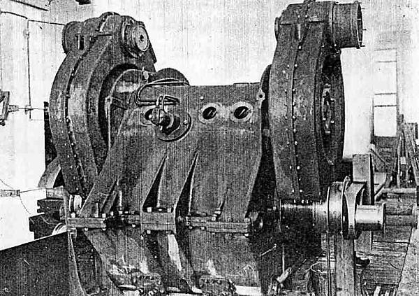
Note the massive proportions of the helical gearwheels and the crankshaft. The gearteeth are slanted in opposite directions to cancel end-thrust.
Why the chap on the right is wearing a fez is a mystery.
Left: Section through the turbine assembly showing the reduction gearing.
For reversing an idler gear between the 2nd and 3rd reduction stages was used, which could be brought into operation by means of a worm gear and a linkage using eccentric shafting. The operation was made purely mechanically by a screw shaft in the cab, like the reversing control of a piston locomotive.
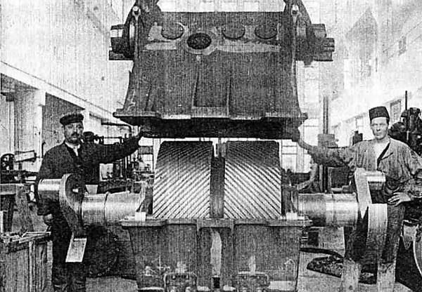
Left: The bottom section (final drive) section of the reduction gearing during assembly.
Source: K B
Left: The intermediate reduction gearing has now been added.
Source: K B
![]()
